CPL03-CB NB-IoT/LTE-M Pulse Contact Sensor User Manual
CPL03-CB NB-IoT/LTE-M Pulse Contact Sensor User Manual
1. Introduction
1.1 What is CPL03-CB NB-IoT/LTE-M Pulse/Contact Sensor
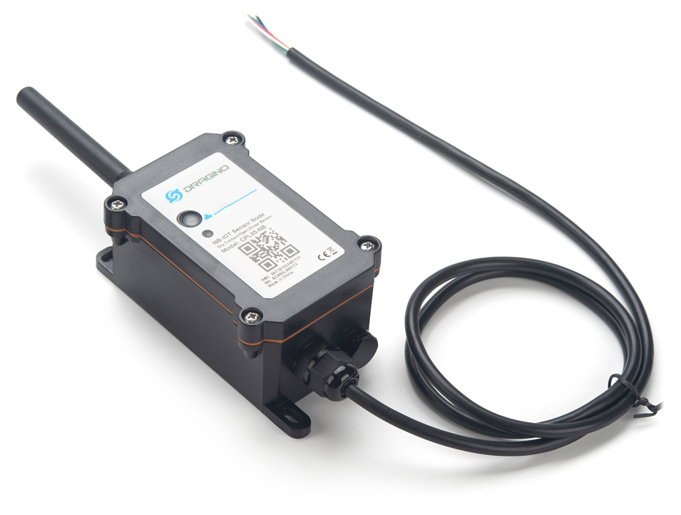
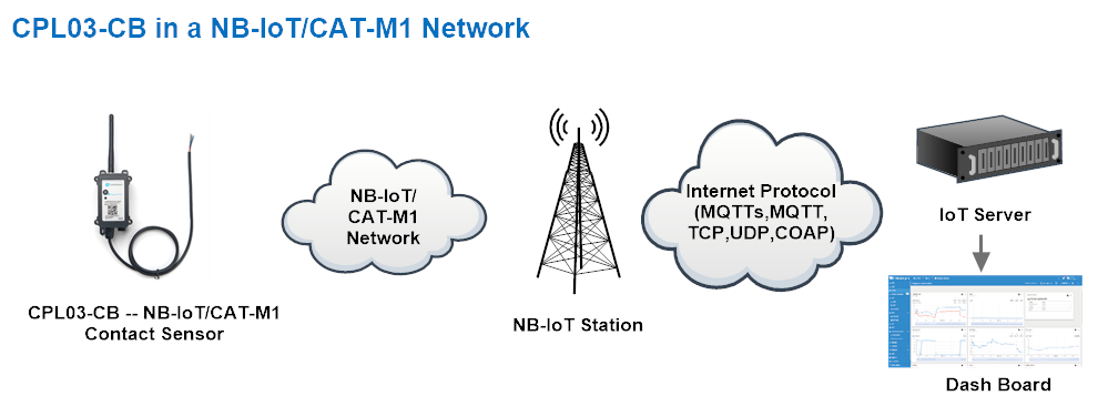
The Dragino CPL03-CB is a NB-IoT/LTE-M Contact Sensor for Internet of Things solution. It detects dry contact status, open time, open counts, and then upload to IoT server via NB-IoT or CAT-M1 network.
The CPL03-CB will send periodically data every day as well as for each dry contact action. It also counts the contact open times and calculate last open duration. User can also disable the uplink for each open/ close event, instead, device can count each open event and uplink periodically.
CPL03-CB supports open alarm feature, user can set open alarm for instant notice.
CPL03-CB is designed for outdoor use. It has a weatherproof enclosure and industrial level battery to work in low to high temperatures.
CPL03-CB supports different uplink methods including MQTT, MQTTs, UDP , TCP or CoAP for different application requirement, and support uplinks to various IoT Servers.
CPL03-CB supports BLE configure and OTA update which make user easy to use.
CPL03-CB is powered by 8500mAh Li-SOCI2 battery, it is designed for long-term use up to several years.
CPL03-CB has optional built-in SIM card and default IoT server connection version. Which makes it works with simple configuration.
1.2 Features
- For -NB Bands: B1/B2/B3/B4/B5/B8/B12/B13/B17/B18/B19/B20/B25/B28/B66/B70/B85
- For -CB Bands: B1/B2/B3/B4/B5/B8/B12/B13/B18/B19/B20/B25/B28/B66/B71/B85
- CAT-M1 / LTE-M Bands: B1/B2/B3/B4/B5/B8/B12/B13/B18/B19/B20/B25/B26/B27/B28/B66/B85
- Upload water flow volume
- Open/Close detect
- Open/Close statistics
- Open Alarm Feature
- IP protection level: IP67
- Multiply Sampling and one uplink
- Uplink via MQTT, MQTTs, TCP, UDP or CoAP
- GNSS for Location Report
- Support Bluetooth v5.1 remote configure and update firmware
- Uplink on periodically
- Downlink to change configure
- 8500mAh Battery for long term use
- Nano SIM card slot for NB-IoT SIM
1.3 Specification
Common DC Characteristics:
- Supply Voltage: 2.6v ~ 3.6v
- Operating Temperature: -40 ~ 85°C
NB-IoT Spec:
NB-IoT Module: BG95-NGFF
Support Bands:
- B1 @H-FDD: 2100MHz
- B2 @H-FDD: 1900MHz
- B3 @H-FDD: 1800MHz
- B4 @H-FDD: 2100MHz
- B5 @H-FDD: 860MHz
- B8 @H-FDD: 900MHz
- B12 @H-FDD: 720MHz
- B13 @H-FDD: 740MHz
- B17 @H-FDD: 730MHz
- B18 @H-FDD: 870MHz
- B19 @H-FDD: 870MHz
- B20 @H-FDD: 790MHz
- B25 @H-FDD: 1900MHz
- B28 @H-FDD: 750MHz
- B66 @H-FDD: 2000MHz
- B70 @H-FDD: 2000MHz
- B85 @H-FDD: 700MHz
Battery:
- Li/SOCI2 un-chargeable battery
- Capacity: 8500mAh
- Self Discharge: <1% / Year @ 25°C
- Max continuously current: 130mA
- Max boost current: 2A, 1 second
Power Consumption
- STOP Mode: 10uA @ 3.3v
- Max transmit power: 350mA@3.3v
1.4 Applications
- Open/Close Detection
- Pulse meter application
- Dry Contact Detection
1.5 Sleep mode and working mode
**Deep Sleep Mode: **Sensor doesn't have any NB-IoT activate. This mode is used for storage and shipping to save battery life.
Working Mode: In this mode, Sensor will work as NB-IoT Sensor to Join NB-IoT network and send out sensor data to server. Between each sampling/tx/rx periodically, sensor will be in IDLE mode), in IDLE mode, sensor has the same power consumption as Deep Sleep mode.
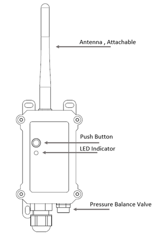
1.6 Button & LEDs
| Behavior on ACT | Function | Action |
|---|---|---|
| Send an uplink | If sensor has already attached to NB-IoT/CAT-M1 network, sensor will send an uplink packet, blue led will blink once. Meanwhile, BLE module will be active and user can connect via BLE to configure device. | |
| Active Device | Green led will fast blink 5 times, device will enter OTA mode for 3 seconds. And then start to attach NB-IoT/CAT-M1 network. Green led will solidly turn on for 5 seconds after joined in network. Once sensor is active, BLE module will be active and user can connect via BLE to configure device, no matter if device attach NB-IoT/CAT-M1 network or not. | |
| Deactivate Device | Red led will solid on for 5 seconds. Means device is in Deep Sleep Mode. |
Note: When the device is executing a program, the buttons may become invalid. It is best to press the buttons after the device has completed the program execution.
1.7 BLE connection
CPL03-CB support BLE remote configure and firmware update.
BLE can be used to configure the parameter of sensor or see the console output from sensor. BLE will be only activate on below case:
- Press button to send an uplink
- Press button to active device.
- Device Power on or reset.
If there is no activity connection on BLE in 60 seconds, sensor will shut down BLE module to enter low power mode.
1.8 Pin Definitions , Switch & SIM Direction
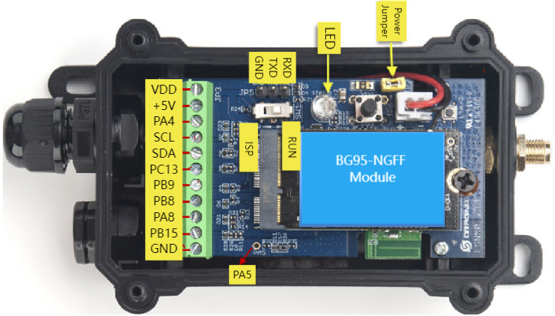
1.8.1 Jumper JP2
Power on Device when put this jumper.
1.8.2 BOOT MODE / SW1
1) ISP: upgrade mode, device won't have any signal in this mode. but ready for upgrade firmware. LED won't work. Firmware won't run.
2) Flash: work mode, device starts to work and send out console output for further debug
1.8.3 Reset Button
Press to reboot the device.
1.8.4 SIM Card Direction
See this link. How to insert SIM Card.
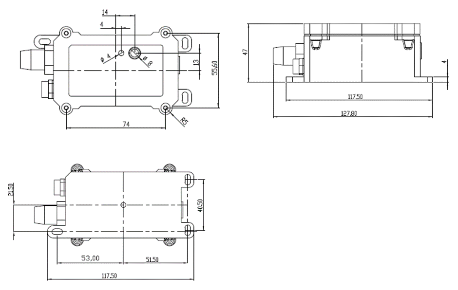
1.9 Mechanical
2. Use CPL03-CB to communicate with IoT Server
2.1 Send data to IoT server via NB-IoT network
The CPL03-CB is equipped with a NB-IoT module, the pre-loaded firmware in CPL03-CB will get environment data from sensors and send the value to local NB-IoT network via the NB-IoT module. The NB-IoT network will forward this value to IoT server via the protocol defined by CPL03-CB.
Below shows the network structure:
There are two version: -GE and -1T version of CPL03-CB.
GE Version: This version doesn't include SIM card or point to any IoT server. User needs to use AT Commands to configure below two steps to set CPL03-CB send data to IoT server.
-
Install NB-IoT SIM card and configure APN. See instruction of Attach Network.
-
Set up sensor to point to IoT Server. See instruction of Configure to Connect Different Servers.
Below shows result of different server as a glance.
| Servers | Dash Board | Comments |
|---|---|---|
| Node-Red | 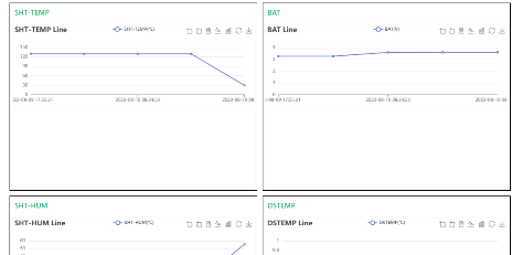 | |
| DataCake | 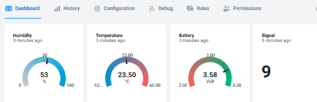 | |
| Tago.IO | ||
| General UDP | Raw Payload. Need Developer to design Dash Board | |
| General MQTT | Raw Payload. Need Developer to design Dash Board | |
| ThingSpeak | 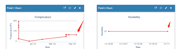 | |
| ThingsBoard | 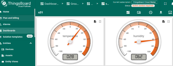 |
1T Version: This version has 1NCE SIM card pre-installed and configure to send value to ThingsEye. User Just need to select the sensor type in ThingsEyeand Activate CPL03-CB and user will be able to see data in ThingsEye. See here for ThingsEye Config Instruction.
2.2 Payload Types
To meet different server requirement, CPL03-CB supports different payload type.
Includes:
-
General JSON format payload. (Type=5)
-
HEX format Payload. (Type=0)
-
ThingSpeak Format. (Type=1)
-
ThingsBoard Format. (Type=3)
User can specify the payload type when choose the connection protocol. Example:
AT+PRO=1,0 // Use COAP Connection & hex Payload
AT+PRO=1,5 // Use COAP Connection & Json Payload
AT+PRO=2,0 // Use UDP Connection & hex Payload
AT+PRO=2,5 // Use UDP Connection & Json Payload
AT+PRO=3,0 // Use MQTT Connection & hex Payload
AT+PRO=3,5 // Use MQTT Connection & Json Payload
AT+PRO=4,0 // Use TCP Connection & hex Payload
AT+PRO=4,5 // Use TCP Connection & Json Payload
2.2.1 General Json Format(Type=5)
2.2.1.1 AT+MOD=1(Real-Time Open/Close Status)
{"IMEI":"868508065628110","IMSI":"460240210507481","Model":"CPL03-CB","work mode":1,"count_mode":0,"tdc send flag":1,"trigger mode":0,"alarm":0,"pa8 level status":0,"count time":0,"door duration":0,"battery":3.17,"signal":24,"time":"2024-12-09T06:43:26Z","latitude":0.000000,"longitude":0.000000,"gps_time":"1970-01-01T00:00:00Z","1":[0,0,0,0,0,4,542,"2024-12-09T06:09:17Z"],"2":[0,0,0,0,0,4,542,"2024-12-09T05:54:17Z"],"3":[0,0,0,0,0,4,542,"2024-12-09T05:39:17Z"],"4":[0,0,0,0,0,13,3463,"2024-12-09T05:24:17Z"],"5":[0,0,0,0,1,13,3463,"2024-12-09T05:09:17Z"],"6":[0,0,0,0,0,13,3463,"2024-12-09T04:54:17Z"],"7":[0,0,0,1,0,0,0,"2024-12-09T04:39:17Z"],"8":[0,0,0,1,0,0,0,"2024-12-09T04:24:17Z"]}
Notice, from above payload:
-
work mode, count_mode, tdc_send flag, trigger mode, alarm, pa8 level status, count time, door duration, Battery, Signal, time, latitude, longitude & GPS time are the value at uplink time.
-
Json entry 1 ~ 8 are the last 1 ~ 8 sampling data as specify by **AT+CLOCKLOG=1,65535,15,8 ** Command. Each entry includes (from left to right): count_mode, tdc_send flag, trigger mode, alarm, pa8 level status, count time, door durationv & Sampling time.
** Count mod: Default=0**
0: Uplink total open door times since factory
1 : Uplink total open door times since last FPORT=2 uplink.
- TDC send flag
When the flag is 1, it means sending packets at normal time intervals.
Otherwise, it is a packet sent at non-TDC time.
- Work mod
0: CPL03-CB-Real-Time Open/Close Status mode.
1: CPL03-CB-3 pulse mode.
- Trigger mod
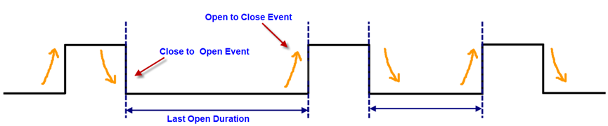
0: The pulse count will increment by one after a close to open event and the last duration is for the open event.
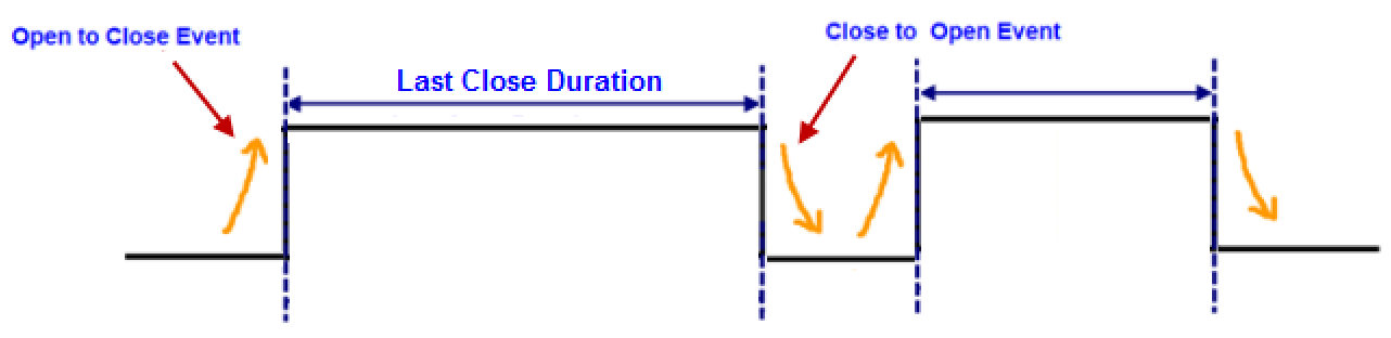
1: The pulse count will increment by one after a open to close event and the last duration is for the close event.
** Alarm**
- pa8 level status
0: The PA8 pin level is low.
1: The PA8 pin level is high.
** count time**
Total pulse/counting base on dry contact trigger event
Range (3 Bytes) : 0x000000 ~ 0xFFFFFF . Max: 16777215
** Door duration**
**1) AT+TTRMOD1=0 **: Dry Contact last open duration.(Unit: sec)
**2) AT+TTRMOD1=1 **: Dry Contact last close duration.(Unit: sec)
2.2.1.2 AT+MOD=2(3 pulse mode)
{"IMEI":"868508065628110","IMSI":"460240210507481","Model":"CPL03-CB","work mode":2,"calc flag":0,"count_mode":0,"tdc send flag":1,"count time1":10,"count time2":20,"count time3":30,"battery":3.17,"signal":26,"time":"2024-12-09T07:17:05Z","latitude":0.000000,"longitude":0.000000,"gps_time":"1970-01-01T00:00:00Z","1":[0,0,15270430,0,0,"2024-12-09T06:09:17Z"],"2":[0,0,15139355,0,0,"2024-12-09T05:54:17Z"],"3":[0,0,14746148,0,0,"2024-12-09T05:39:17Z"],"4":[0,0,14156328,0,0,"2024-12-09T05:24:17Z"],"5":[0,0,14287399,0,0,"2024-12-09T05:09:17Z"],"6":[0,0,14221866,0,0,"2024-12-09T04:54:17Z"],"7":[0,0,14484005,0,0,"2024-12-09T04:39:17Z"],"8":[0,0,14418467,0,0,"2024-12-09T04:24:17Z"]}
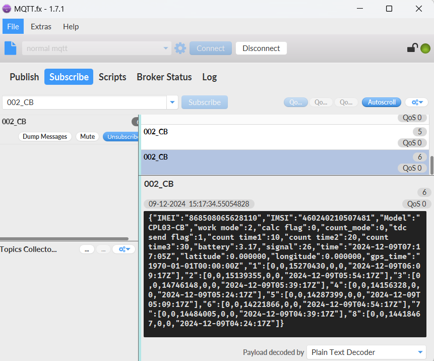
Notice, from above payload:
-
work mode, calc flag, count_mode, tdc send flag, count time1, count time2, count time3, Battery, Signal, time, Latitude, Longitude & GPS_time are the value at uplink time.
-
Json entry 1 ~ 8 are the last 1 ~ 8 sampling data as specify by **AT+CLOCKLOG=1,65535,15,8 ** Command. Each entry includes (from left to right): calc flag, count_mode, count time1, count time2, count time3, Sampling time.
Max COUNT for each port is 16777215. Exceed this number will reset to 1.
Count mod: Default=0
0: Uplink total count times since factory
1: Uplink total count times since last FPORT=2 uplink.
- TDC send flag
When the flag is 1, it means sending packets at normal time intervals.
Otherwise, it is a packet sent at non-TDC time.
- Work mod
0: Real-Time Open/Close Status mode.
1: 3 x pulse counting mode.
** Calculate Flag**
The calculate flag is a user define field, IoT server can use this filed to handle different meter with different pulse factor. For example, if there are 100 water meters, meter 1 ~50 are 1 liter/pulse and meter 51 ~ 100 has 1.5 liter/pulse.
User can set calculate flag to 1 for meter 1~50 and 2 for meter 51 ~ 100, So IoT Server can use this field for calculation.
Default value: 0.
Range (3 bits): (b)000 ~ (b) 111
Refer: Set Calculate Flag
** Port1 Total Pulse(PA8 of pin)**
Range (3 Bytes) : 0x000000 ~ 0xFFFFFF . Max: 16777215.Exceed this number will reset to 1.
** Port2 Total Pulse(PA4 of pin)**
Range (3 Bytes) : 0x000000 ~ 0xFFFFFF . Max: 16777215.Exceed this number will reset to 1.
** Port3 Total Pulse(PB15 of pin)**
Range (3 Bytes) : 0x000000 ~ 0xFFFFFF . Max: 16777215.Exceed this number will reset to 1.
- ** Latitude & Longitude**
With GPS enabled, the node will automatically search for latitude and longitude each time it is reset. And the node automatically locates and uplinks each time it passes GTDC time after activation.
2.2.2 HEX format Payload(Type=0)
2.2.2.1 AT+MOD=1(Real-Time Open/Close Status)
f868508065628110f460240210507481506e0c9a1810000000000000675692dc0000000000000000000000000000000400021e6756898d0000000400021e675686090000000400021e675682850000000d000d8767567f010400000d000d8767567b7d0000000d000d87675677f9010000000000006756747501000000000000675670f1
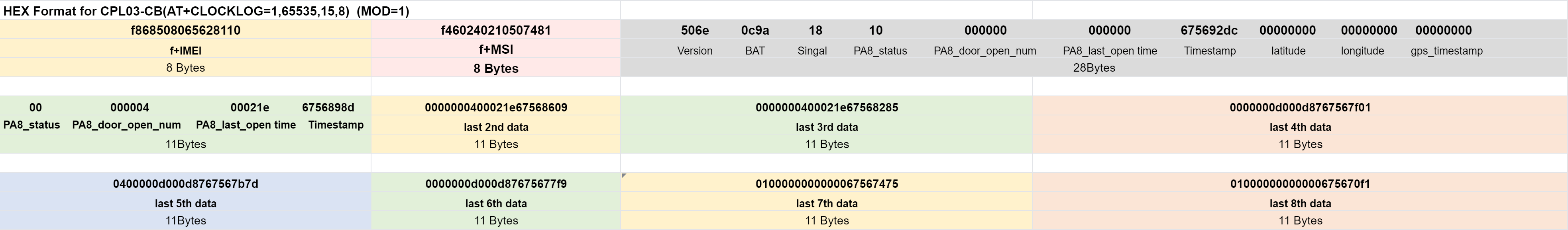
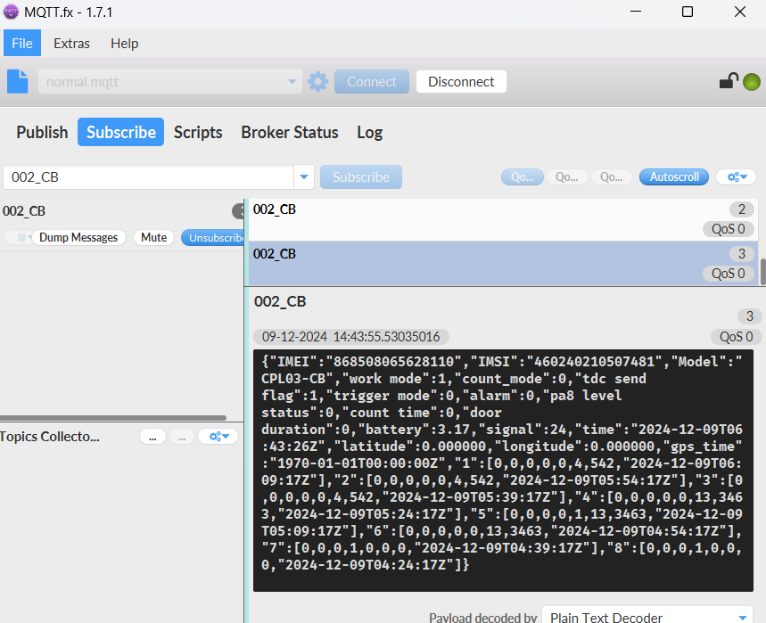
If we use the MQTT client to subscribe to this MQTT topic, we can see the following information when the NB sensor uplink data.
Version:
These bytes include the hardware and software version.
Higher byte: Specify Sensor Model: 0x50 for CPL03-CB
Lower byte: Specify the software version: 0x64=100, means firmware version 1.0.0
BAT (Battery Info):
Ex1: 0x0dda = 3546mV
Signal Strength:
NB-IoT Network signal Strength.
Ex1: 0x15 = 21
0 -113dBm or less
1 -111dBm
2...30 -109dBm... -53dBm
31 -51dBm or greater
99 Not known or not detectable
PA8 Status:
PA8 Status consists of Count mode, TDC send flag, Trigger mode, PA8 alarm status, PA8 level status.
(PA8 level Status=(count_mode<<5) | (tdc_send_flag<<4) | (0<<3) | (trigger_mode[0]<<2) | (pa8_alarm_status<<1) | pa8_level_status)
**Timestamp: **
Unit Timestamp Example: 650abc40(H) = 1695202368(D)
Put the decimal value into this link(https://www.epochconverter.com)) to get the time.
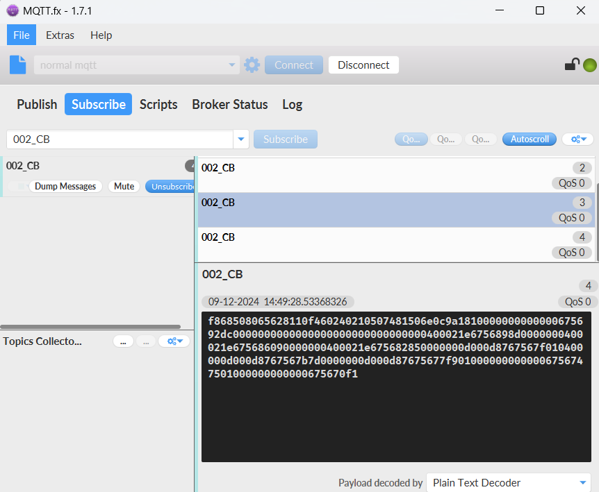
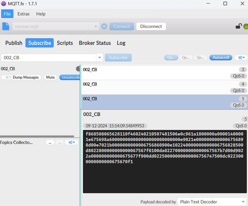
2.2.2.2 AT+MOD=2(3 pulse mode)
f868508065628110f460240210507481506e0c961a1800000a00001400001e675698a600000000000000000000000000e9021e0000000000006756898d00e7021b0000000000006756860900e102240000000000006756828500d8022800000000000067567f0100da022700000000000067567b7d00d9022a000000000000675677f900dd02250000000000006756747500dc0223000000000000675670f1
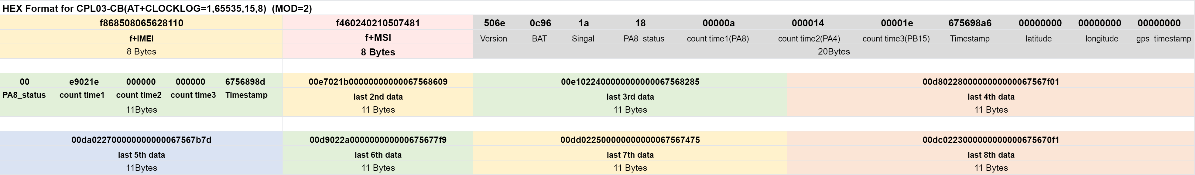
If we use the MQTT client to subscribe to this MQTT topic, we can see the following information when the NB sensor uplink data.
Version:
These bytes include the hardware and software version.
Higher byte: Specify Sensor Model: 0x50 for CPL03-CB
Lower byte: Specify the software version: 0x6e=110, means firmware version 1.1.0
BAT (Battery Info):
Ex1: 0x0dda = 3546mV
Signal Strength:
NB-IoT Network signal Strength.
Ex1: 0x15 = 21
0 -113dBm or less
1 -111dBm
2...30 -109dBm... -53dBm
31 -51dBm or greater
99 Not known or not detectable
PA8 Status:
PA8 Status consists of Count mode, TDC send flag, Calculate flag.
(PA8 level Status=(count_mode<<5) | (tdc_send_flag<<4) | (1<<3) |calculate_flag)
**Timestamp: **
Unit Timestamp Example: 650abc40(H) = 1695202368(D)
Put the decimal value into this link(https://www.epochconverter.com)) to get the time.
2.2.3 ThingsBoard Payload(Type=3)
Type3 payload special design for ThingsBoard, it will also configure other default server to ThingsBoard.
2.2.3.1 AT+MOD=1(Real-Time Open/Close Status)
{ "topic": "002_CB", "payload": { "IMEI": "868508065628110", "IMSI": "460240210507481", "Model": "CPL03-CB", "work mode": 1, "count_mode": 0, "tdc send flag": 1, "trigger mode": 0, "alarm": 0, "pa8 level status": 0, "count time": 0, "door duration": 0, "battery": 3.17, "signal": 24, "time": "2024-12-09T06:58:38Z", "latitude": 0.0, "longitude": 0.0, "gps_time": "1970-01-01T00:00:00Z", "1": [0, 0, 0, 0, 0, 4, 542, "2024-12-09T06:09:17Z"], "2": [0, 0, 0, 0, 0, 4, 542, "2024-12-09T05:54:17Z"], "3": [0, 0, 0, 0, 0, 4, 542, "2024-12-09T05:39:17Z"], "4": [0, 0, 0, 0, 0, 13, 3463, "2024-12-09T05:24:17Z"], "5": [0, 0, 0, 0, 1, 13, 3463, "2024-12-09T05:09:17Z"], "6": [0, 0, 0, 0, 0, 13, 3463, "2024-12-09T04:54:17Z"], "7": [0, 0, 0, 1, 0, 0, 0, "2024-12-09T04:39:17Z"], "8": [0, 0, 0, 1, 0, 0, 0, "2024-12-09T04:24:17Z"] } }

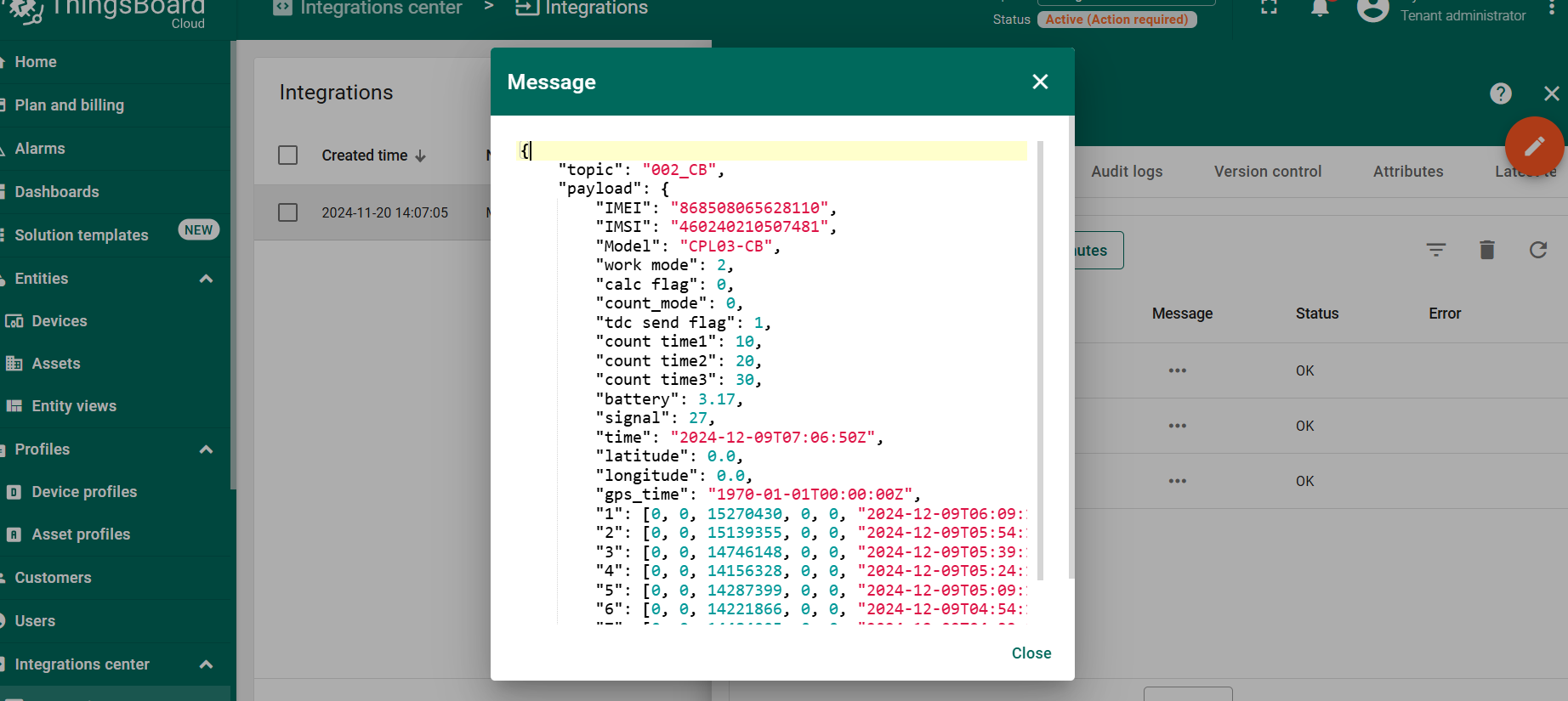
2.2.3.2 AT+MOD=2(3 pulse mode)
{ "topic": "002_CB", "payload": { "IMEI": "868508065628110", "IMSI": "460240210507481", "Model": "CPL03-CB", "work mode": 2, "calc flag": 0, "count_mode": 0, "tdc send flag": 1, "count time1": 10, "count time2": 20, "count time3": 30, "battery": 3.17, "signal": 27, "time": "2024-12-09T07:06:50Z", "latitude": 0.0, "longitude": 0.0, "gps_time": "1970-01-01T00:00:00Z", "1": [0, 0, 15270430, 0, 0, "2024-12-09T06:09:17Z"], "2": [0, 0, 15139355, 0, 0, "2024-12-09T05:54:17Z"], "3": [0, 0, 14746148, 0, 0, "2024-12-09T05:39:17Z"], "4": [0, 0, 14156328, 0, 0, "2024-12-09T05:24:17Z"], "5": [0, 0, 14287399, 0, 0, "2024-12-09T05:09:17Z"], "6": [0, 0, 14221866, 0, 0, "2024-12-09T04:54:17Z"], "7": [0, 0, 14484005, 0, 0, "2024-12-09T04:39:17Z"], "8": [0, 0, 14418467, 0, 0, "2024-12-09T04:24:17Z"] } }
2.2.4 ThingSpeak Payload(Type=1)
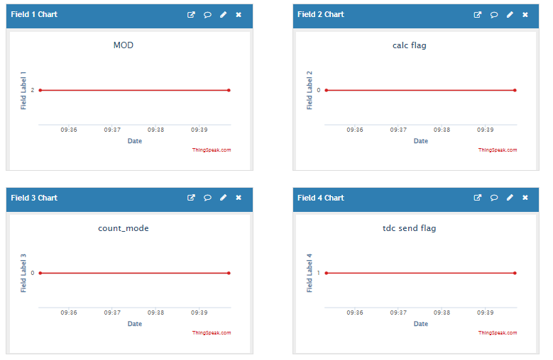
2.2.4.1 AT+MOD=1(Real-Time Open/Close Status)
field1=work mod value&field2=count mode value&ield3=tdc send flag value&field4=trigger mode value&field5=alarm value&field6=pa8 level status value&field7=count time value&field8=door duration value
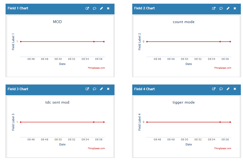
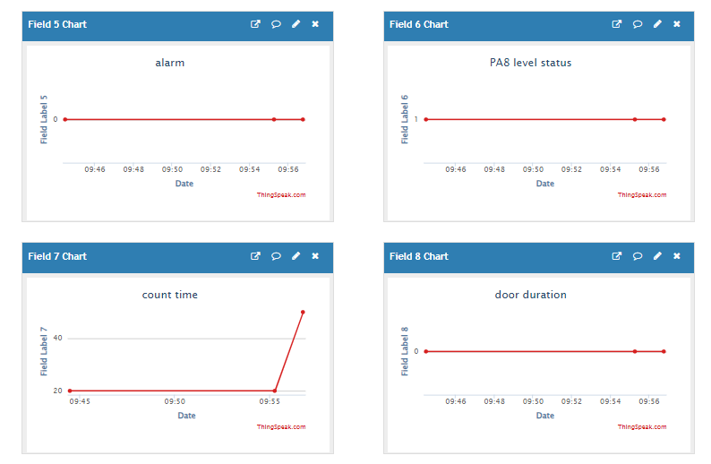
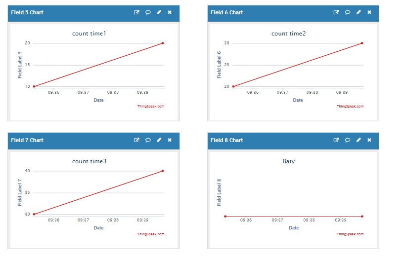
2.2.4.2 AT+MOD=2(3 pulse mode)
field1=work mod value&field2=calc flag value&field3=count mode value&ield4=tdc send flag value&field5=count time1 value&field6=count time2 value&field7=count time3 value&field8=Battery value
3. Configure CPL03-CB
3.1 Configure Methods
CPL03-CB supports below configure method:
-
AT Command via Bluetooth Connection (Recommended): BLE Configure Instruction.
-
AT Command via UART Connection : See UART Connection.
3.2 Serial Access Password
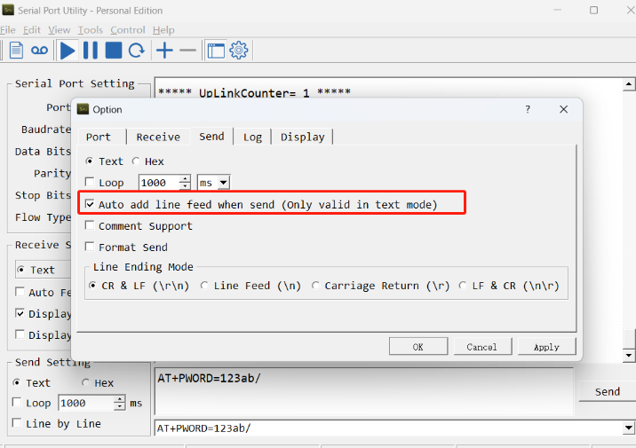
After the Bluetooth or UART connection is successful, use the Serial Access Password to enter the AT command window.
The label on the box of the node will print the initial password: AT+PIN=xxxxxx, and directly use the six-digit password to access the AT instruction window.
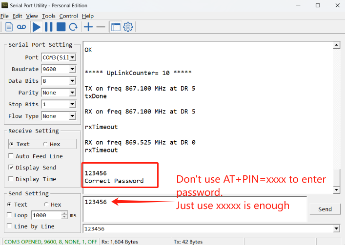
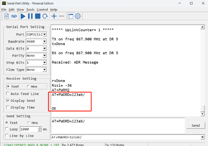
If you need to change the password, use AT+PWORD=xxxxxx (6 characters), -CB nodes only support lowercase letters.
Note: After entering the command, you need to add a line break, and you can also set automatic line breaks in the Bluetooth tool or UART connection tool.
3.3 AT Commands Set
AT+<CMD>? : Help on <CMD>
AT+<CMD> : Run <CMD>
AT+<CMD>=<value> : Set the value
AT+<CMD>=? : Get the value
AT : Attention
AT? : Short Help
ATZ : MCU Reset
AT+TDC : Application Data Transmission Interval
AT+CFG : Print all configurations
AT+DEUI : Get or set the Device ID
AT+5VT : Set extend the time of 5V power
AT+PRO : Choose agreement
AT+RXDL : Extend the sending and receiving time
AT+DNSCFG : Get or Set DNS Server
AT+GETSENSORVALUE : Returns the current sensor measurement
AT+NOUD : Get or Set the number of data to be uploaded
AT+CDP : Read or Clear cached data
AT+SERVADDR : Server Address
MQTT Management
AT+CLIENT : Get or Set MQTT client
AT+UNAME : Get or Set MQTT Username
AT+PWD : Get or Set MQTT password
AT+PUBTOPIC : Get or Set MQTT publish topic
AT+SUBTOPIC : Get or Set MQTT subscription topic
AT+MQOS : Set the QoS level of MQTT
Information
AT+FDR : Factory Data Reset
AT+FDR1 : Reset parameters to factory default values except for passwords
AT+PWORD : Serial Access Password
AT+LDATA : Get the last upload data
AT+CDP : Read or Clear cached data
3.4 Mode switching
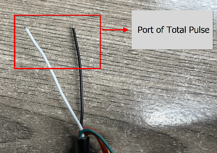
3.4.1 Real-Time Open/Close Status
Default working mode
AT Command: AT+MOD=1
Downlink Command: 0x02 01
The wiring of the Real-Time Open/Close Status mode is as follows:
3.4.1.1 Set Alarm Base on Timeout
It only takes effect when AT+MOD=1.
CPL03-CB can monitor the timeout for a status change, this feature can be used to monitor some events such as door opening too long etc. Related Parameters are:
1. Keep Status: Status to be monitor
Keep Status = 1: Monitor Close to Open event
Keep Status = 0: Monitor Open to Close event
2. Keep Time: Timeout to send an Alarm
Range 0 ~ 65535(0xFFFF) seconds.
If** keep time = 0**, Disable Alarm Base on Timeout feature.
If keep time > 0, device will monitor the keep status event and send an alarm when status doesn’t change after timeout.
- AT Command: AT+TTRIG
AT+TTRIG=1,30 --> When the Keep Status change from connect to disconnect, and device remains in disconnect status for more than 30 seconds. CPL03-CB will send an uplink packet, the Alarm bit (the second bit of 1st byte of payload) on this uplink packet is set to 1.
**AT+TTRIG=0,0 ** --> Default Value, disable timeout Alarm.
- **Downlink Command: 0x0F **
Format: Command Code (0x0F) followed by 8 bytes, each parameter after 0F takes 4 bytes.
Example: Downlink payload: **0x0F 00 00 00 01 00 00 00 1E ** // AT+TTRIG=1,30 30(D)=0x1E(H)
3.4.1.2 TTRIG timeout status alarm
Feature: Set TTRIG of Alarm interval. (unit: minute)
It only takes effect when AT+MOD=1. It needs to be used with AT+TTRIG . When TTRIG times out and causes an alarm, and the status does not change subsequently, an alarm packet will be sent at the alarm interval.
AT Command: AT+TTRALARM
Example:
- AT+TTRALARM=0 // disable continuous alarm
- AT+TTRALARM=60 // Set the alarm interval to 60 minutes (unit: minutes)
Downlink Command: 0x0A
Example:
- Downlink payload: 0x0A 00 // AT+TTRALARM=0
- Downlink payload: 0x0A 3C // AT+TTRALARM=60, 60(D)=0x3C(H)
3.4.1.3 Clear current door open count
Feature: Manually Clear current door open count
**AT Command: AT+CLRC ** // Clear current open count and the duration of the last open
Downlink Command: 0xA1 00 // AT+CLRC
3.4.1.4 Enable / Disable Alarm
Feature: Enable/Disable Alarm for open/close event. Default value 0.
AT Command: AT+DISALARM
| Command Example | Function | Response |
| AT+DISALARM=1 | End node will only send packets in TDC time. | OK |
| AT+DISALARM=0 | End node will send packets in TDC time or status change for door sensor | OK |
Downlink Command: 0x0B
Example: Downlink payload: **0x0B 00 **// AT+DISALARM=0
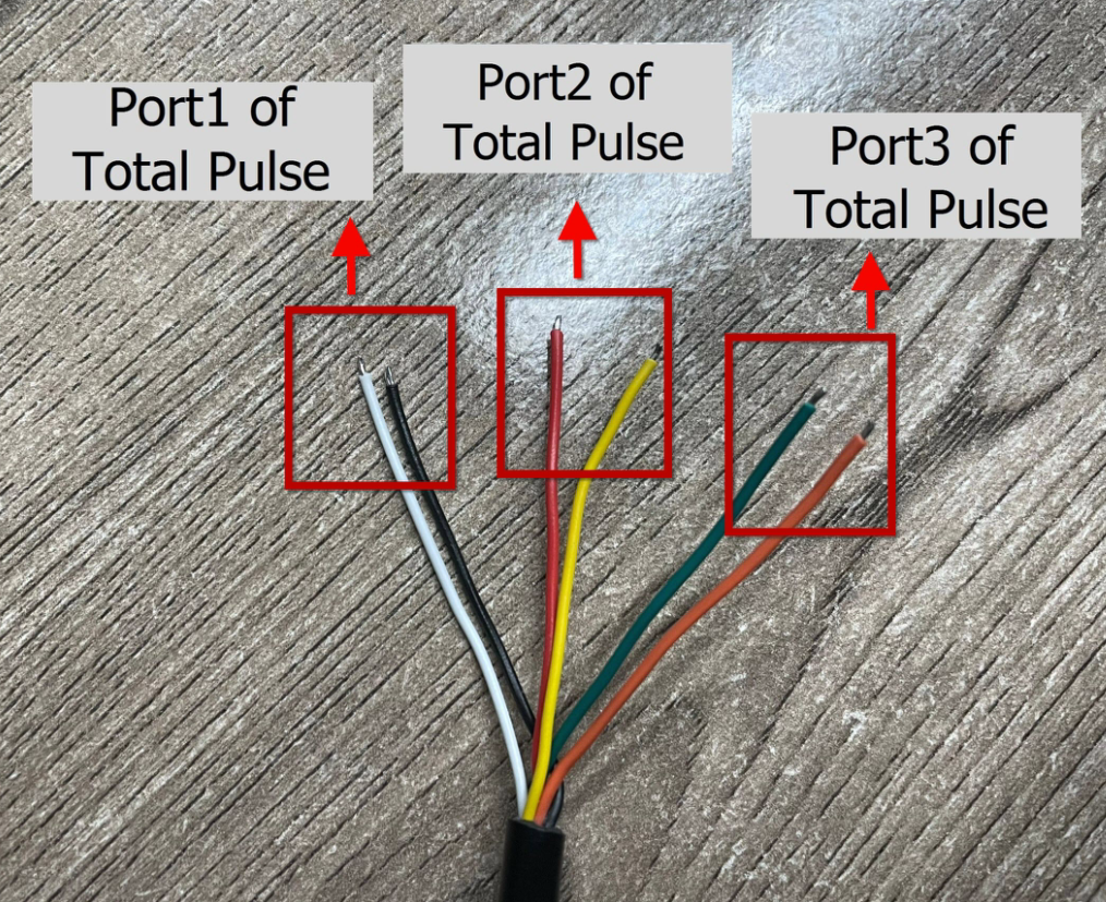
3.4.2 pulse mode
To use this working mode, you need to set AT+MOD=2.
AT Command: AT+MOD=2
Downlink Command: 0x02 02
The wiring of the three pulse counting mode are as follows:
For AT+MOD=2:
3.4.2.1 Port1,Port2,Port3 count mode
- **Port1: **Get or Set the trigger interrupt mode(PA8)
** AT Command: AT+TTRMOD1 0: Signal falling edge(Default), 1: Signal raising edge**
         Ex1: AT+TTRMOD1=0   // Count and trigger from close to open (falling edge), default.

         Ex2: AT+TTRMOD1=1   // Count and trigger from open to close (rising edge).
** Downlink Command: 0x0C **
Example: 0x0C00 // AT+TTRMOD1=0
- **Port2: **Get or Set the trigger interrupt mode(PA4)
** AT Command: AT+TTRMOD2 0: Signal falling edge(Default), 1: Signal raising edge**
         Ex1: AT+TTRMOD2=0   // Count and trigger from close to open (falling edge), default.

         Ex2: AT+TTRMOD2=1   // Count and trigger from open to close (rising edge).
** Downlink Command: 0x0D **
Example: 0x0D01 // AT+TTRMOD2=1
- Port3: Get or Set the trigger interrupt mode(PB15)
** AT Command: AT+TTRMOD3 0: Signal falling edge(Default), 1: Signal raising edge**
         Ex1: AT+TTRMOD3=0   // Count and trigger from close to open (falling edge), default.

         Ex2: AT+TTRMOD3=1   // Count and trigger from open to close (rising edge).
** Downlink Command: 0x0E **
Example: 0x0E00 // AT+TTRMOD3=0
3.4.2.2 Set the calculate flag
Feature: Set the calculate flag**(Range is 0 to 7), It only takes effect when AT+MOD=2.**
** AT Command:AT+CALCFLAG=aa ( Default : 0 )**
Example: AT+CALCFLAG=2
** Downlink Command: 0xA3**
Example: 0xA3 02 // AT+CALCFLAG=2
3.4.2.3 Set Count value
Feature: Manually set the count number
In Real-Time Open/Close Status mode work mode, the Total_pulse set by the "AT+SETCNT=1,xx" command.
In 3 x pulse counting mode work mode, the Port1_Total_pulse(PA8) set by the "AT+SETCNT=1,xx" command.
** AT Command: AT+SETCNT**
        AT+SETCNT=1,aa

        AT+SETCNT=2,aa

        AT+SETCNT=3,aa
There is no corresponding downlink command.
There is a downlink instruction to clear the count: **0x10 00, **when the user downlinks 0x10 00, the count of Port1, Port2 and Port3 clears to 0.
3.5 Count Mod
Feature: Manually set the count mode.
AT Command: AT+COUNTMOD 0: Accumulative (Default), 1: Reset after uplink.
Example: AT+COUNTMOD=0
Downlink Command: 0xA2
Example: 0xA2 00 // AT+COUNTMOD=0
3.6 Test Uplink and Change Update Interval
By default, Sensor will send uplinks every 2 hours.
User can use below commands to change the uplink interval.
AT Command: AT+TDC
Example: AT+TDC=7200 // Set Update Interval to 7200 seconds
Downlink Command: 0x01
Format: Command Code (0x01) followed by 3 bytes.
Example: 12 hours= 43200 seconds 43200(D)=0xA8C0(H)
Downlink Payload: `01 00 A8 C0` // AT+TDC=43200, Set Update Interval to 12 hours.
Note: User can also push the button for more than 1 seconds to activate an uplink.
3.7 Set the receiving time
Feature: Extend the receiving time
AT Command: AT+RXDL
Example: AT+RXDL=1000 // Set the receiving time delay to 1000ms
Downlink Command: 0x03
Format: Command Code (0x03) followed by 3 bytes.
Example: Downlink Payload: 03 00 03 E8// AT+RXDL=1000
3.8 Reset
Feature: Trig a reset of the MCU.
AT Command: ATZ
Downlink Command: 0x04FF
3.9 +5V
Feature: Set extend the time of 5V power.
**AT Command: AT+5VT **
Example: AT+5VT=2000 // Set extend the time of 5V power to 2000 ms
Downlink Command: 0x05
Format: Command Code (0x05) followed by 3 bytes.
Example: Downlink Payload: 05 00 07 D0// AT+5VT=2000
3.10 Set the QoS level
This command is used to set the QoS level of MQTT.
AT command:
- **AT+MQOS=xx **// 0~2
Downlink Command: 0x07
Format: Command Code (0x07) followed by 1 byte.
Ex1: Downlink payload: 0x07 00 // AT+MQOS=0
Ex2: Downlink payload: 0x07 01 // AT+MQOS=1
3.11 Clock logging
Sometimes when we deploy lots of end nodes in field. We want all sensors sample data at the same time, and upload these data together for analyze. In such case, we can use clock loging feature.
We can use this command to set the start time of data recording and the time interval to meet the requirements of the specific collection time of data.
AT command: AT+CLOCKLOG=a,b,c,d
a: 0: Disable Clock logging. ** 1: **Enable Clock Logging
**b: **Specify First sampling start second: range **(0 ~ 3599, 65535) ** // **Note: **If parameter b is set to 65535, the log period starts after the node accesses the network and sends packets.
**c: **Specify the sampling interval: range (0 ~ 255 minutes)
**d: **How many entries should be uplink on every TDC (max 32)
Note: To disable clock recording, set the following parameters: AT+CLOCKLOG=1,65535,0,0
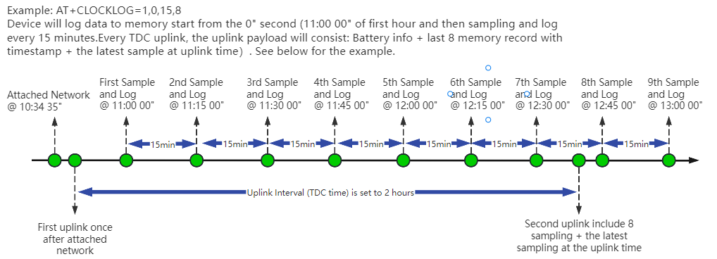
Example:
AT+CLOCKLOG=1,65535,1,5
After the node sends the first packet, data is recorded to the memory at intervals of 1 minute. For each TDC uplink, the uplink load will include: battery information + the last 5 memory records (payload + timestamp).
Note: Users need to synchronize the server time before configuring this command. If the server time is not synchronized before this command is configured, the command takes effect only after the node is reset.
Downlink command: 0x08
Format: Command Code (0x08) followed by 5 bytes.
- Example 1: Downlink Payload:** 08 01 FFFF 0F 08** // Set SHT record time: AT+CLOCKLOG=1,65535,15,8
- Example 2: Downlink Payload:** 08 01 04B0 0F 08** // Set SHT record time: AT+CLOCKLOG=1,1200,15,8
Note: When entering the downlink payload, there must be no Spaces between bytes.
3.12 Set the TLS mode
Refer to this link (MQTT Connection to send data to Tago.io)to use the TLS mode.
AT Command: AT+TLSMOD
**Example 1: ** AT+TLSMOD=0,0 // Disable TLS Mode.
Example 2: AT+TLSMOD=1,0 // No authentication
                 AT+TLSMOD=1,1     // Perform server authentication

                 AT+TLSMOD=1,2     // Perform server and client authentication if requested by the remote server
Downlink command: 0x09
Format: Command Code (0x09) followed by 2 bytes.
Example1: Downlink Payload: 09 00 00// AT+TLSMOD=0,0
Example2: Downlink Payload: 09 01 02// AT+TLSMOD=1,2
3.13 Set GNSS open time
Extend the time to turn on GNSS. The automatic GPS location time is extended when the node is activated.
AT Command: AT+GNSST
Example: AT+GNSST=30 // Set the GPS positioning time to 30 seconds
Downlink command: 0x10
Format: Command Code (0x10) followed by 2 bytes.
Example: Downlink Payload: 10 00 1E// AT+GNSST=30
3.14 Turn on/off GPS
**AT Command: AT+GPS **
**Ex1: **AT+GPS=0 // Turn off GPS
**Ex2: **AT+GPS=1 // Turn on GPS
Downlink command: 0x11
Format: Command Code (0x11) followed by 1 byte.
Example: Downlink Payload: 11 01// AT+GPS=1
3.15 Set GPS positioning interval
Feature: Set GPS positioning interval (unit: hour).
When GPS is enabled, the node automatically locates and uplinks each time it passes GTDC time after activation.
AT Command: AT+GTDC
Example: AT+GTDC=24 // Set the GPS positioning interval to 24h.
Downlink command: 0x12
Format: Command Code (0x12) followed by 3 bytes.
Example: 24 hours: 24(D)=0x18(H)
Downlink Payload: `12 00 00 18`// AT+GTDC=24
3.16 Set the search network time
Feature: Get or Set the time to join the network(unit: minutes).
AT Command: AT+CSQTIME
Example: AT+CSQTIME=10 // Set the search time to 10 minutes.
Downlink command: 0x13
Format: Command Code (0x13) followed by 1 byte.
Example: Downlink Payload: 13 0A// AT+CSQTIME=10
3.17 Set the IPv4 or IPv6
This command is used to set IP version.
AT command:
- **AT+IPTYPE=1 **// IPv4
- **AT+IPTYPE=2 **// IPv6
3.18 Configure Network Category to be Searched for under LTE RAT.
AT command: AT+IOTMOD=xx
xx: 0: eMTC
        **1:** NB-IoT

        **2:** eMTC and NB-IoT
3.19 Factory data reset
Two different restore factory Settings configurations.
AT command:
- **AT+FDR **// Reset Parameters to Factory Default.
- **AT+FDR1 **// Reset parameters to factory default values except for passwords.
3.20 Set CoAP option
Feature: Set CoAP option, follow this link to set up the CoaP protocol.
AT command: AT+URI1~AT+URI8
**AT+URI1=11,"i" **// "i/" indicates that the endpoint supports observation mode. In -CB products, fixed setting AT+URI1=11,"i"
**AT+URI2=11,"CoAP endpoint URl" **// 11 is a fixed parameter.
**Example: ** i/13a35fbe-9515-6e55-36e8-081fb6aacf86
AT+URI1=11,"i"
AT+URI2=11,"13a35fbe-9515-6e55-36e8-081fb6aacf86"
-->If multiple groups of CoAP endpoint urls:
AT+URI3=11,"i"
AT+URI4=11,"CoAP endpoint URl"
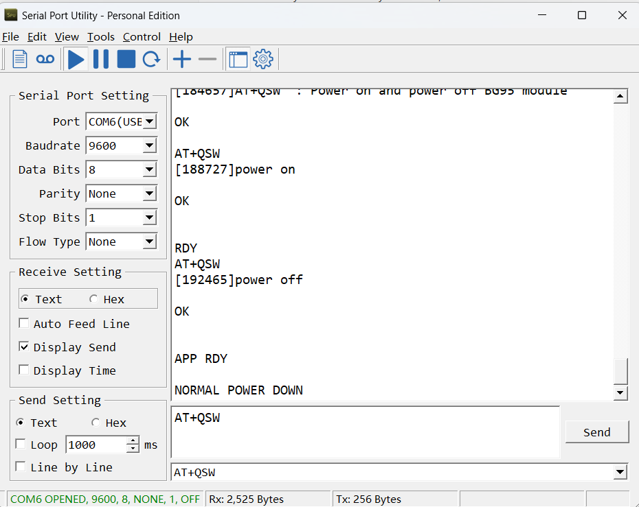
3.21 Power on / power off BG95 module
This command is used to power on and power off BG95 module.
- AT command: AT+QSW
The module is powered on after the command is sent for the first time, and powered off after the command is sent again.
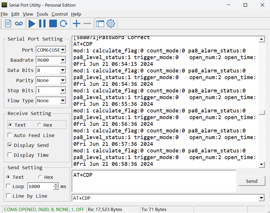
3.22 Example Query saved historical records
- AT command: AT+CDP
This command can be used to search the saved history, recording up to 32 groups of data, each group of historical data contains a maximum of 100 bytes.
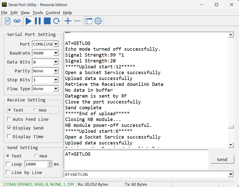
3.23 Uplink log query
- AT command: AT+GETLOG
This command can be used to query upstream logs of data packets.
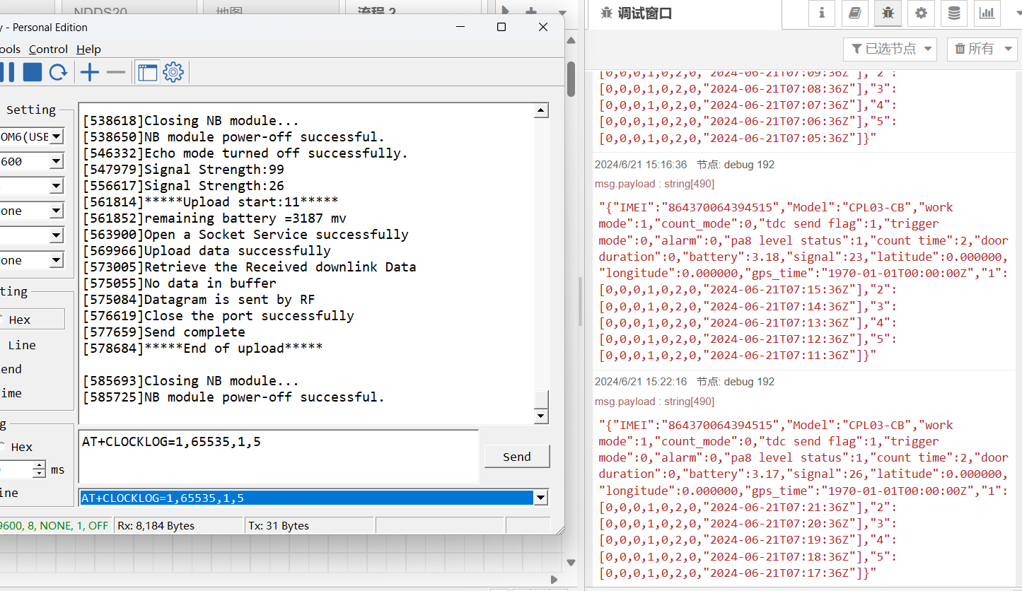
3.24 Set the downlink debugging mode(Since firmware v1.1.0)
Feature: Enable or disable downlink debugging mode. (Since TE platform update, the platform version selection is no longer needed; only downlink debugging can be toggled.)
AT command: AT+DOWNTE
| Command Example | Function/Parameters | Response/Explanation |
|---|---|---|
| AT+DOWNTE=? | Get current Settings | 0,0 (default) OK |
| AT+DOWNTE=0,a | a: Enable/Disable downlink debugging | 0: Disable downlink debugging mode. 1: Enable downlink debugging mode (users can view original downlink messages). |
(Note: The first parameter is fixed to 0 and only the second parameter is configurable.)
Example:
- AT+DOWNTE=0,1 → Enable downlink debugging mode.
- AT+DOWNTE=0,0 → Disable downlink debugging mode.
**Downlink Command: **
No downlink commands for feature
3.25 Domain name resolution settings(Since firmware v1.1.1)
Feature: Set static DNS resolution IP address.
AT command: AT+BKDNS
| Command Example | Function/Parameters | Response/Explanation |
|---|---|---|
| AT+BKDNS=? | Get current Settings | 1,0,NULL (default) OK |
AT+BKDNS=a,b,c | a: Enable/Disable static DNS resolution. | 0: Disable static DNS resolution 1: Enable static DNS resolution. The ip address will be saved after the domain name is resolved, if the next domain name resolution fails, the last saved ip address will be used. |
| b: Meaningless. | Set to 0. | |
| c: Set the IP address manually. | The format is the same as AT+SERVADDR. If domain name resolution fails, this ip address will be used directly, if domain name resolution succeeds, parameter c will be updated to the successfully resolved IP address. |
Example:
- AT+BKDNS=0,0,NULL // Disable static DNS resolution.
- AT+BKDNS=1,0,NULL // Enable static DNS resolution.
- AT+BKDNS=1,0,3.69.98.183,1883 // Enable static DNS resolution, if domain name resolution succeeds, the node uses the ip address successfully resolved and saves it to parameter c. If the domain name resolution fails, use the manually set ip address: 3.69.98.183 for communication.
**Downlink Command: **
No downlink commands for feature.
4. Battery & Power Consumption
CPL03-CB use ER26500 + SPC1520 battery pack. See below link for detail information about the battery info and how to replace.
Battery Info & Power Consumption Analyze .
5. Firmware update
User can change device firmware to:
-
Update with new features.
-
Fix bugs.
Firmware and changelog can be downloaded from : Firmware download link
Methods to Update Firmware:
-
(Recommended way) OTA firmware update via BLE: Instruction.
-
Update through UART TTL interface : Instruction.
6. FAQ
6.1 How can I access the BG95-NGFF AT Commands?
User can access to BG95-NGFF directly and send AT Commands.
6.2 How to Connect Dry contacts or Wet Contacts
CPL03-CB can only be connected to dry contacts by default, and the wiring method is to connect the two ports of dry contacts to the VDD pin and pulse input pin of CPL03-CB respectively.
If you want to connect a wet contact, you need to change the original wiring method. The wiring method is that the GND of the wet contact is connected to the GND of CPL03-CB, and the pulse output is connected to the pulse pin, but the pulse output voltage of the wet contact must be less than 3.6V.
6.3 What is the maximum total number of pulses for CPL03? What happens after the maximum total number of pulses is reached?
The maximum total number of pulses for CPL03 is three bytes FF FF FF (16,777,215).
The count is reset when the maximum total number of pulses is reached.
6.4 General Manual for -CB , -CS models
Users can follow the instructions in this link to see how to configure to connect to different servers.
6.5 Why is there no LED response when I press the button on the solar panel model?
If the LED does not light up when you press the button, it may be because the battery has entered protection mode.
Solution: To reactivate the battery, simply expose the solar panel to direct sunlight. For more details, please refer to: Battery Protection State (Apply to Solar Panel + Li-ion battery)
6.6 Why does the CPL03-CB have 6 wires externally but only 4 inside the terminal block?
The CPL03-CB is designed to support three dry contact inputs. Each dry contact requires two connections: one to a pulse input pin and one to VDD.
At the field sensor side, all six wires are available:
- Pulse Input 1: White wire → PA8 & Black → VDD
- Pulse Input 2: Red wire → PA4 & Yellow → VDD
- Pulse Input 3: Green wire → PB15 & Orange → VDD
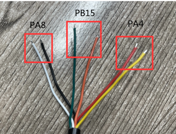
At the device side, only four wires are terminated:
To simplify field wiring and avoid connecting multiple wires to the same VDD terminal (which can be difficult due to the small screw terminal size), the yellow and orange wires are internally connected (soldered) to the black wire at the device end. This means only one wire (Black) needs to be connected to the VDD, while the other end of the cable still provides six individual wires for easy connection to three dry contacts.
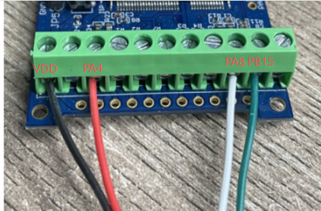
This design improves terminal block connection reliability and simplifies installation.
7. Order Info
Part Number: CPL03-CB-XX
XX:
-
GE: General version ( Exclude SIM card)
-
1T: with 1NCE* 10 years 500MB SIM card and Pre-configure to ThingsEye server
8. Packing Info
Package Includes:
-
CPL03-CB NB-IoT/LTE-M Pulse/Contact sensor x 1
-
External antenna x 1
Dimension and weight:
-
Device Size: 13.0 x 5 x 4.5 cm
-
Device Weight: 150g
-
Package Size / pcs : 14.0 x 8x 5 cm
-
Weight / pcs : 180g
9. Support
-
Support is provided Monday to Friday, from 09:00 to 18:00 GMT+8. Due to different timezones we cannot offer live support. However, your questions will be answered as soon as possible in the before-mentioned schedule.
-
Provide as much information as possible regarding your enquiry (product models, accurately describe your problem and steps to replicate it etc) and send a mail to Support@dragino.cc.
0