MR-03/12/25-NB/NS – NB-IoT Microwave Radar Distance Sensor User Manual
MR-03/12/25-NB/NS – NB-IoT Microwave Radar Distance Sensor User Manual
1. Introduction
1.1 What is NB-IoT Microwave Radar distance Sensor
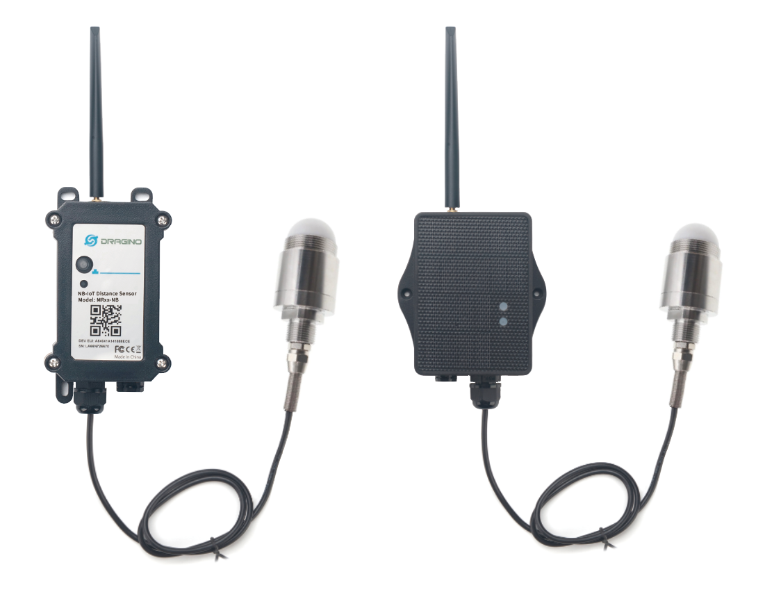
The Dragino MR-03/12/25-NB/NS is a NB-IoT Microwave Radar distance Sensor for Internet of Things solution. It uses 80Ghz Microwave to detect the distance between sensor and diferent objects. Diferent from ultrosonic or Lidar measurement. Microwave Radar is more reliable for condensation / dusty environment. It can sense correct distance even there is water or think dust on top of the sensor.
The MR-03/12/25-NB/NS can be applied to scenarios such as horizontal distance measurement, parking management system, object proximity and presence detection, intelligent trash can management system, robot obstacle avoidance, automatic control, sewer, etc.
MR-03/12/25-NB/NS supports different uplink methods including MQTT, MQTTs, UDP, TCP & COAP for different application requirement, and support uplinks to various IoT Servers.
MR-03/12/25-NB/NS supports BLE configure and OTA update which make user easy to use.
MR-03/12/25-NB/NS is powered by **8500mAh Li-SOCI2 battery or solar powered + Li-ion battery **, it is designed for long-term use up to several years.
MR-03/12/25-NB/NS has optional built-in SIM card and default IoT server connection version. Which makes it works with simple configuration.
1.2 Features
- NB-IoT Bands: B1/B2/B3/B4/B5/B8/B12/B13/B17/B18/B19/B20/B25/B28/B66/B70/B85 @H-FDD
- Ultra-low power consumption
- 80GHz Microwave Radar for distance detection
- Measure Range : 3m: 200 ~ 3000mm; 12m: 200 ~ 12000mm; 25m: 200 ~ 25000mm
- Accuracy: ± 20mm
- Resolution: 1mm
- Measurement Angle : 7.6 degrees horizontal and 7.6 degrees vertical
- Multiply Sampling and one uplink
- Support Bluetooth v5.1 remote configure and update firmware
- Uplink on periodically
- Downlink to change configure
- 8500mAh Li/SOCl2 Battery (MR-XX-NB)
- Solar panel + 3000mAh Li-ion battery (MR-XX-NS)
1.3 Specification
Common DC Characteristics:
- Supply Voltage: 2.5v ~ 3.6v
- Operating Temperature: -40 ~ 85°C
Radar probe Spec:
- Measuring Method: FMCW
- Frequency: 80 GHz
- Measure Range : 3m: 200 ~ 3000mm; 12m: 200 ~ 12000mm; 25m: 200 ~ 25000mm
- Accuracy: ± 20mm
- Resolution: 1mm
- Measurement Angle : 7.6 degrees horizontal and 7.6 degrees vertical
NB-IoT Spec:
NB-IoT Module: BC660K-GL
Support Bands:
- B1 @H-FDD: 2100MHz
- B2 @H-FDD: 1900MHz
- B3 @H-FDD: 1800MHz
- B4 @H-FDD: 2100MHz
- B5 @H-FDD: 860MHz
- B8 @H-FDD: 900MHz
- B12 @H-FDD: 720MHz
- B13 @H-FDD: 740MHz
- B17 @H-FDD: 730MHz
- B18 @H-FDD: 870MHz
- B19 @H-FDD: 870MHz
- B20 @H-FDD: 790MHz
- B25 @H-FDD: 1900MHz
- B28 @H-FDD: 750MHz
- B66 @H-FDD: 2000MHz
- B70 @H-FDD: 2000MHz
- B85 @H-FDD: 700MHz
Battery:
- Li/SOCI2 un-chargeable battery
- Capacity: 8500mAh
- Self Discharge: <1% / Year @ 25°C
- Max continuously current: 130mA
- Max boost current: 2A, 1 second
Power Consumption:
- STOP Mode: 10uA @ 3.3v
- Max transmit power: 350mA@3.3v
1.4 Applications
- Horizontal distance measurement
- Liquid level measurement
- Parking management system
- Object proximity and presence detection
- Intelligent trash can management system
- Robot obstacle avoidance
- Automatic control
- Sewer
- Bottom water level monitoring
1.5 Installation
Sensor measure direction and angle is as below. When install the sensor, please make sure the sensor direct to object.
1.6 Sleep mode and working mode
**Deep Sleep Mode: **Sensor doesn't have any NB-IoT activate. This mode is used for storage and shipping to save battery life.
Working Mode: In this mode, Sensor will work as NB-IoT Sensor to Join NB-IoT network and send out sensor data to server. Between each sampling/tx/rx periodically, sensor will be in IDLE mode), in IDLE mode, sensor has the same power consumption as Deep Sleep mode.
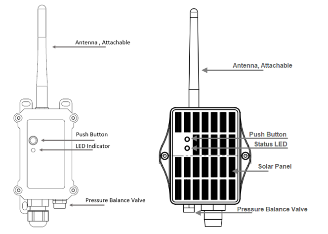
1.7 Button & LEDs
| Behavior on ACT | Function | Action |
|---|---|---|
| Send an uplink | If sensor has already attached to NB-IoT network, sensor will send an uplink packet, blue led will blink once. Meanwhile, BLE module will be active and user can connect via BLE to configure device. | |
| Active Device | Green led will fast blink 5 times, device will enter OTA mode for 3 seconds. And then start to attach NB-IoT network. Once sensor is active, BLE module will be active and user can connect via BLE to configure device, no matter if device attach NB-IoT network or not. | |
| Deactivate Device | Red led will solid on for 5 seconds. Means device is in Deep Sleep Mode. |
Note: When the device is executing a program, the buttons may become invalid. It is best to press the buttons after the device has completed the program execution.
1.8 BLE connection
MR-03/12/25-NB/NS support BLE remote configure and firmware update.
BLE can be used to configure the parameter of sensor or see the console output from sensor. BLE will be only activate on below case:
- Press button to send an uplink
- Press button to active device.
- Device Power on or reset.
If there is no activity connection on BLE in 60 seconds, sensor will shut down BLE module to enter low power mode.
1.9 Pin Definitions , Switch & SIM Direction
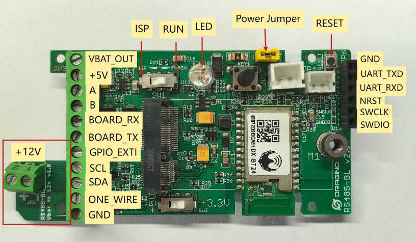
1.9.1 Jumper JP2
Power on Device when put this jumper.
1.9.2 BOOT MODE / SW1
1) ISP: upgrade mode, device won't have any signal in this mode. but ready for upgrade firmware. LED won't work. Firmware won't run.
2) Flash: work mode, device starts to work and send out console output for further debug
1.9.3 Reset Button
Press to reboot the device.
1.9.4 SIM Card Direction
See this link. How to insert SIM Card.
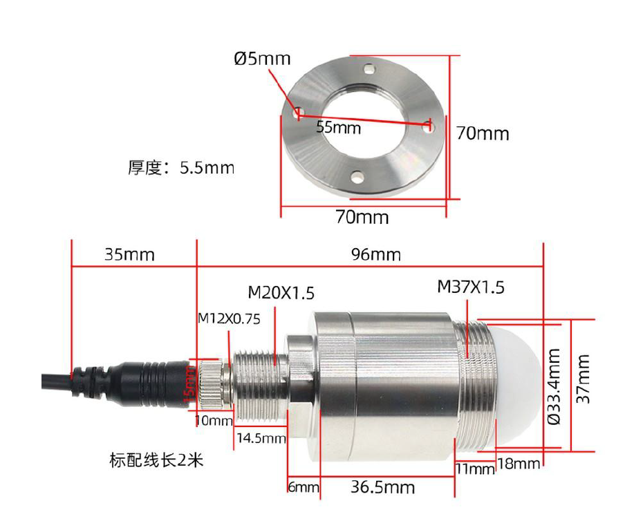
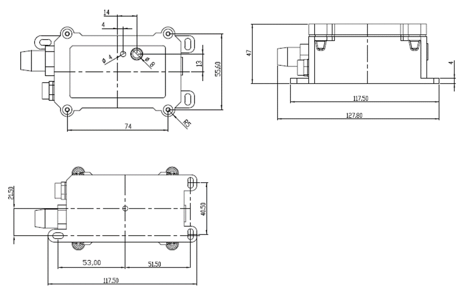
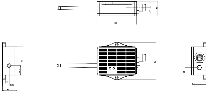
1.10 Mechanical
1.10.1 for NB version
1.10.2 for NS version
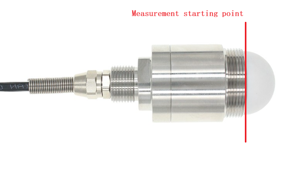
1.11 Measure starting point
2. Use MR-03/12/25-NB/NS to communicate with IoT Server
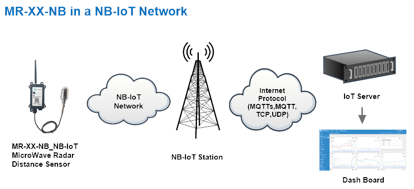
2.1 Send data to IoT server via NB-IoT network
The MR-03/12/25-NB/NS is equipped with a NB-IoT module, the pre-loaded firmware in MR-03/12/25-NB/NS will get environment data from sensors and send the value to local NB-IoT network via the NB-IoT module. The NB-IoT network will forward this value to IoT server via the protocol defined by MR-03/12/25-NB/NS.
Below shows the network structure:
There are two version: -GE and -1T version of MR-03/12/25-NB/NS.
GE Version: This version doesn't include SIM card or point to any IoT server. User needs to use AT Commands to configure below two steps to set MR-03/12/25-NB/NS send data to IoT server.
-
Install NB-IoT SIM card and configure APN. See instruction of Attach Network.
-
Set up sensor to point to IoT Server. See instruction of Configure to Connect Different Servers.
Below shows result of different server as a glance.
| Servers | Dash Board | Comments |
|---|---|---|
| Node-Red | 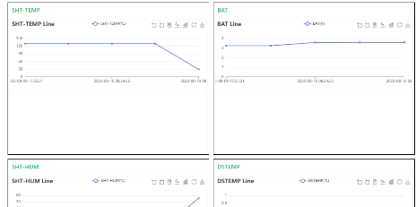 | |
| DataCake | 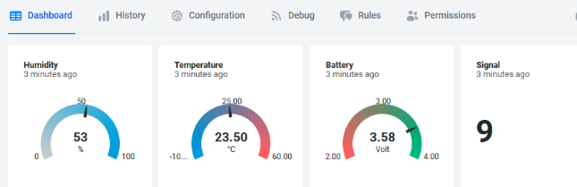 | |
| Tago.IO | ||
| General UDP | Raw Payload. Need Developer to design Dash Board | |
| General MQTT | Raw Payload. Need Developer to design Dash Board | |
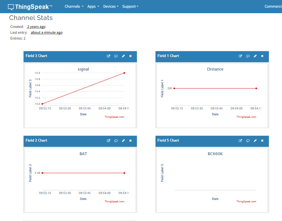
| ThingSpeak | 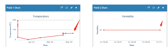 | |
| ThingsBoard | 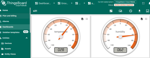 |
1T Version: This version has 1NCE SIM card pre-installed and configure to send value to ThingsEye. User Just need to select the sensor type in ThingsEyeand Activate MR-03/12/25-NB/NS and user will be able to see data in ThingsEye. See here for ThingsEye Config Instruction.
2.2 Payload Types
To meet different server requirement, MR-03/12/25-NB/NS supports different payload type.
Includes:
-
General JSON format payload. (Type=5)
-
HEX format Payload. (Type=0)
-
ThingSpeak Format. (Type=1)
-
ThingsBoard Format. (Type=3)
User can specify the payload type when choose the connection protocol. Example:
AT+PRO=1,0 // Use COAP Connection & hex Payload
AT+PRO=1,5 // Use COAP Connection & Json Payload
AT+PRO=2,0 // Use UDP Connection & hex Payload
AT+PRO=2,5 // Use UDP Connection & Json Payload
AT+PRO=3,0 // Use MQTT Connection & hex Payload
AT+PRO=3,5 // Use MQTT Connection & Json Payload
AT+PRO=4,0 // Use TCP Connection & hex Payload
AT+PRO=4,5 // Use TCP Connection & Json Payload
2.2.1 General Json Format(Type=5)
This is the General Json Format. As below:
{"IMEI":"863663062798914","Model":"MR03/12/25-NB","distance":200,"interrupt":0,"interrupt_level":0,"battery":3.37,"signal":16,"1":[200,"2025/12/05 01:11:24"],"2":[200,"2025/12/05 01:10:24"],"3":[200,"2025/12/05 01:09:24"],"4":[200,"2025/12/05 01:08:24"],"5":[200,"2025/12/05 01:07:24"],"6":[200,"2025/12/05 01:06:24"],"7":[200,"2025/12/05 01:05:24"],"8":[200,"2025/12/05 01:04:24"]}
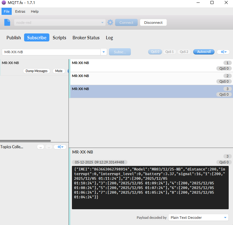
Notice, from above payload:
-
Distance , Interrupt, Interrupt_level, Battery, Signal, time are the value at uplink time.
-
Json entry 1 ~ 8 are the last 1 ~ 8 sampling data as specify by **AT+CLOCKLOG=1,65535,15,8 ** Command. Each entry includes (from left to right): Distance, Sampling time.
2.2.2 HEX format Payload(Type=0)
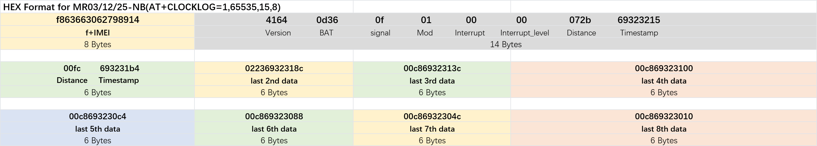
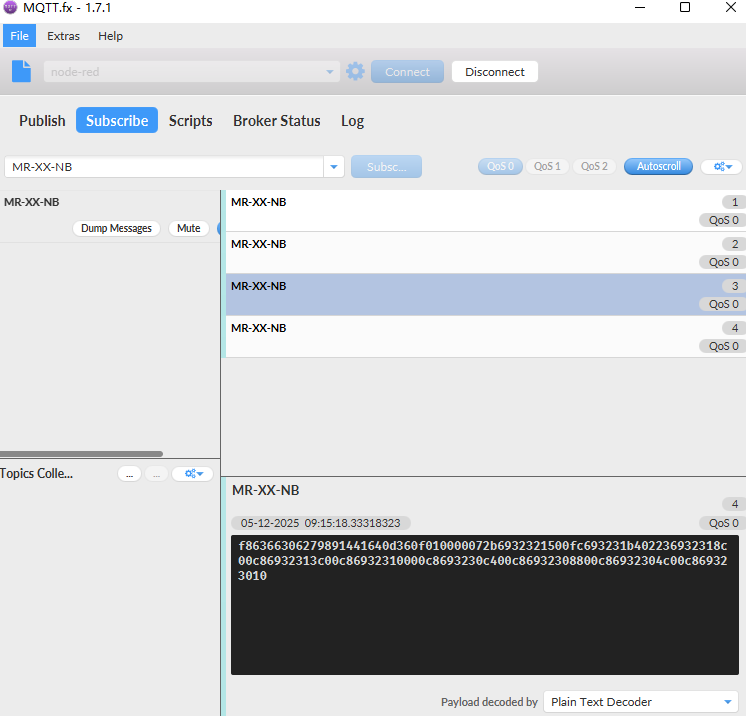
This is the HEX Format. As below:
f86366306279891441640d360f010000072b6932321500fc693231b402236932318c00c86932313c00c86932310000c8693230c400c86932308800c86932304c00c869323010
If we use the MQTT client to subscribe to this MQTT topic, we can see the following information when the NB sensor uplink data.
Version:
These bytes include the hardware and software version.
Higher byte: Specify Sensor Model: 0x41 for MR-03/12/25-NB/NS
Lower byte: Specify the software version: 0x64=100, means firmware version 1.0.0
BAT (Battery Info):
Ex1: 0x0D36 = 3382mV
Signal Strength:
NB-IoT Network signal Strength.
Ex1: 0x0f = 15
0 -113dBm or less
1 -111dBm
2...30 -109dBm... -53dBm
31 -51dBm or greater
99 Not known or not detectable
Distance:
Distance between sensor probe to the first object. (unit: mm)
For example, if the data you get from the register is 0x01 0x40, the distance between the sensor and the measured object is** 072B(H) = 1835(D) = 1835mm.**
Notice: The distance has a special value :
0x00C8: Invalid reading (probe beyond effective range or entering detection blind zone) or probe not detected.
Interrupt:
This data field shows if this packet is generated by interrupt or not.
Example:
0x00: Normal uplink packet.
0x01: Interrupt Uplink Packet.
Interrupt Level:
This byte shows whether the interrupt is triggered by a high or low level.
Ex1: 0x00 Interrupt triggered by falling edge (low level)
**Ex2: **0x01 Interrupt triggered by rising edge (high level)
**TimeStamp: **
Unit TimeStamp Example: 650d02ff(H) = 1695351551(D)
Put the decimal value into this link(https://www.epochconverter.com)) to get the time.
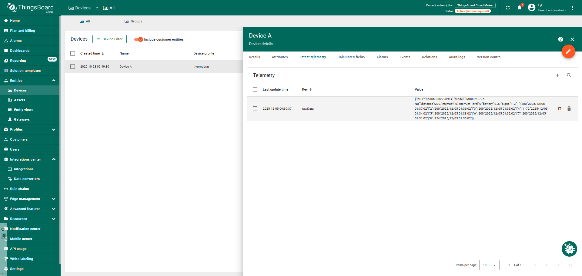
2.2.3 ThingsBoard Payload(Type=3)
Type3 payload special design for ThingsBoard, it will also configure other default server to ThingsBoard.
{ "IMEI": "863663062798914", "Model": "MR03/12/25-NB", "distance": 200, "interrupt": 0, "interrupt_level": 0, "battery": 3.37, "signal": 12, "1": [200,"2025/12/05 01:37:02"], "2": [200,"2025/12/05 01:36:02"], "3": [200,"2025/12/05 01:35:02"], "4": [1172,"2025/12/05 01:34:02"], "5": [200,"2025/12/05 01:33:02"], "6": [200,"2025/12/05 01:32:02"], "7": [200,"2025/12/05 01:31:02"], "8": [254,"2025/12/05 01:30:02"] }
2.2.4 ThingSpeak Payload(Type=1)
This payload meets ThingSpeak platform requirement. It includes only four fields. Form 1~3 are:
Distance, Battery & Signal. This payload type only valid for ThingsSpeak Platform.
As below:
field1=Distance value & field2=Battery value & field3=Signal value
2.3 Test Uplink and Change Update Interval
By default, Sensor will send uplinks every 2 hours
User can use below commands to change the uplink interval.
**AT Command: AT+TDC **
Example: AT+TDC=7200 // Set Update Interval to 7200 seconds
Downlink Commands: 0x01
Format: Command Code (0x01) followed by 3 bytes.
Example: 12 hours= 43200 seconds 43200(D)=0xA8C0(H)
Downlink Payload: `01 00 A8 C0` // AT+TDC=43200, Set Update Interval to 12 hours.
Note: User can also push the button for more than 1 seconds to activate an uplink.
2.4 Set Alarm Distance
On each sampling define by AT+CLOCKLOG=1,65535,15,8 ( default 15 minutes), when the value exceed the range, it will trigger an Alarm and immediately sends a uplink.
AT command: AT+ALARM1
AT+ALARM=AA,BB
- AA: Dec value for Alarm low threshold, BB: Dec value for Alarm high threshold
- When 0xAA=0, and 0xBB≠0, Alarm trigger when higher than max
- When 0xAA≠0, and 0xBB =0xFFFF, Alarm trigger when lower than min
- When 0xAA≠0 and 0xBB≠0, Alarm trigger when higher than max or lower than min
Example:
AT+ALARM1=100,200 // For diatance 1, alarm when < 100 or higher than 200.(Min:50cm, Max:2000cm)
Downlink command: 0x08
Format: Command Code (0x08) followed by 8 bytes. The first 4 bytes after 08 are set to the limit range of distance 1, and the last 4 bytes after 08 are set to the limit range of distance 2.
**Example: **
Downlink Payload: ** 08 00 64 00 C8 00 C8 01 2C ** // AT+ALARM1=100,200 & AT+ALARM2=200,300
Downlink Payload: 08 00 00 00 00 00 00 00 00// AT+ALARM1=0,0 & AT+ALARM2=0,0 Distance 1 and Distance 2 alarms are not enabled.
2.5 Set Interrupt Mode(0x06)
Feature, Set Interrupt mode for GPIO_EXTI.
AT Command: AT+INTMOD
| Command Example | Function | Response |
|---|---|---|
| AT+INTMOD=? | Show current interrupt mode | 0 OK the mode is 0 = No interruption |
| AT+INTMOD=2 | Set Transmit Interval (Disable Interrupt), (Trigger by rising and falling edge) (Trigger by falling edge) (Trigger by rising edge) | OK |
Downlink Command: 0x06
Format: Command Code (0x06) followed by 3 bytes.
This means that the interrupt mode of the end node is set to 0x000003=3 (rising edge trigger), and the type code is 06.
Example 1: Downlink Payload: 06000000 // Turn off interrupt mode
Example 2: Downlink Payload: 06000003 // Set the interrupt mode to rising edge trigger
2.6 Clock logging
Sometimes when we deploy lots of end nodes in field. We want all sensors sample data at the same time, and upload these data together for analyze. In such case, we can use clock loging feature.
We can use this command to set the start time of data recording and the time interval to meet the requirements of the specific collection time of data.
- AT Command: AT+CLOCKLOG=a,b,c,d
a: 0: Disable Clock logging. ** 1: **Enable Clock Logging
**b: **Specify First sampling start second: range **(0 ~ 3599, 65535) ** // **Note: **If parameter b is set to 65535, the log period starts after the node accesses the network and sends packets.
**c: **Specify the sampling interval: range (0 ~ 255 minutes)
**d: **How many entries should be uplink on every TDC (max 32)
Note: To disable clock recording, set the following parameters: AT+CLOCKLOG=1,65535,0,0
Example:
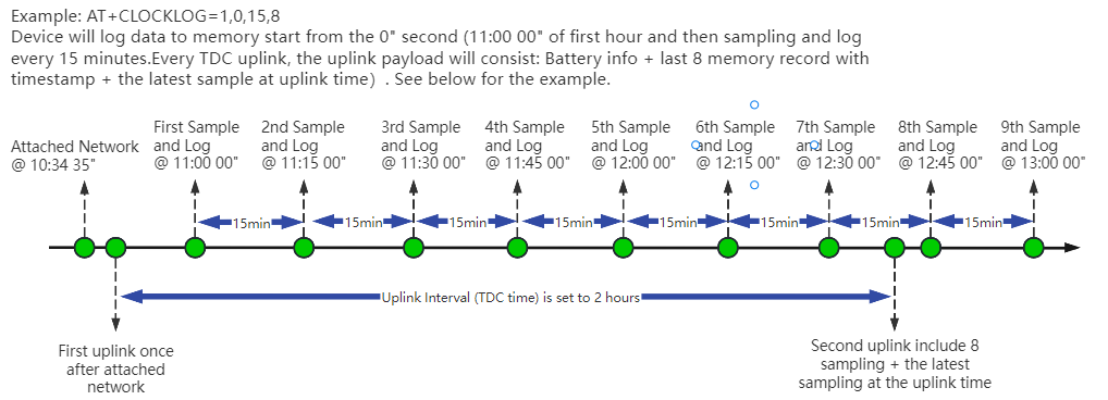
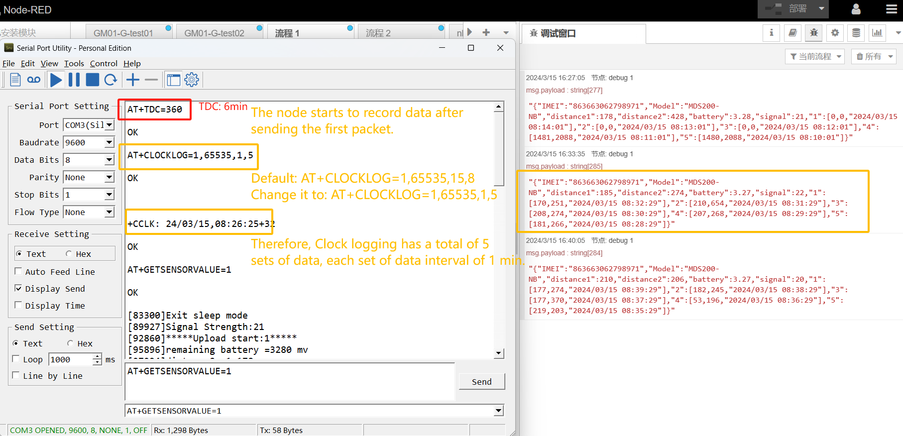
AT+CLOCKLOG=1,65535,1,5
After the node sends the first packet, data is recorded to the memory at intervals of 1 minute. For each TDC uplink, the uplink load will include: battery information + the last 5 memory records (payload + timestamp).
Note: Users need to synchronize the server time before configuring this command. If the server time is not synchronized before this command is configured, the command takes effect only after the node is reset.
- Downlink command: 0x0A
Format: Command Code (0x0A) followed by 5 bytes.
- Example 1: Downlink Payload:** 0A01FFFF0F08** // Set SHT record time: AT+CLOCKLOG=1,65535,15,8
- Example 1: Downlink Payload:** 0A0104B00F08** // Set SHT record time: AT+CLOCKLOG=1,1200,15,8
Note: When entering the downlink payload, there must be no Spaces between bytes.
2.7 Datalog Function
2.7.1 Unix TimeStamp
MR-03/12/25-NB/NS uses Unix TimeStamp format based on
User can get this time from link: https://www.epochconverter.com/ :
Below is the converter example
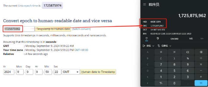
So, 1725875962 means that the current time is Monday, September 9, 2024 at 9:59 AM.
2.7.2 Poll sensor value
User can poll sensor value based on timestamps from the server. Below is the downlink command.
| 1 byte | 4 bytes | 4 bytes |
|---|---|---|
| 31 | Timestamp start | Timestamp end |
Timestamp start and Timestamp end use Unix TimeStamp format as mentioned above. Devices will reply with all data log during this time period.
For example, downlink command 31 6932 44D4 6932 46B4
Is to check 2025/12/5 02:35:00 to 2025/12/5 02:43:00's data
2.7.3 Datalog Uplink payload
The Datalog poll reply uplink will use below payload format.
Retrieval data payload:
| Size(bytes) | 2 | 2 | 4 |
|---|---|---|---|
| value | Distance | Reserve | Timestamp |
**Function Description: **This feature is only used when the clock logging feature is turned on. one uplink packet can send 64 groups of stored data totaling 512 bytes.
Example(For MQTT.fx):
If user sends below downlink command:
Where : Start time: 693244D4= time 25/12/5 02:35:00
Stop time: 693246B4= time 25/12/5 02:43:00
MR-03/12/25-NB/NS will uplink this payload.
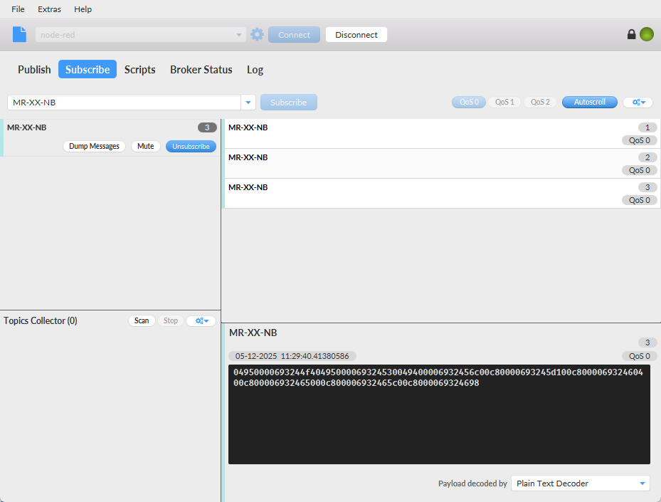
04950000693244f40495000069324530049400006932456c00c80000693245d100c800006932460400c800006932465000c800006932465c00c8000069324698
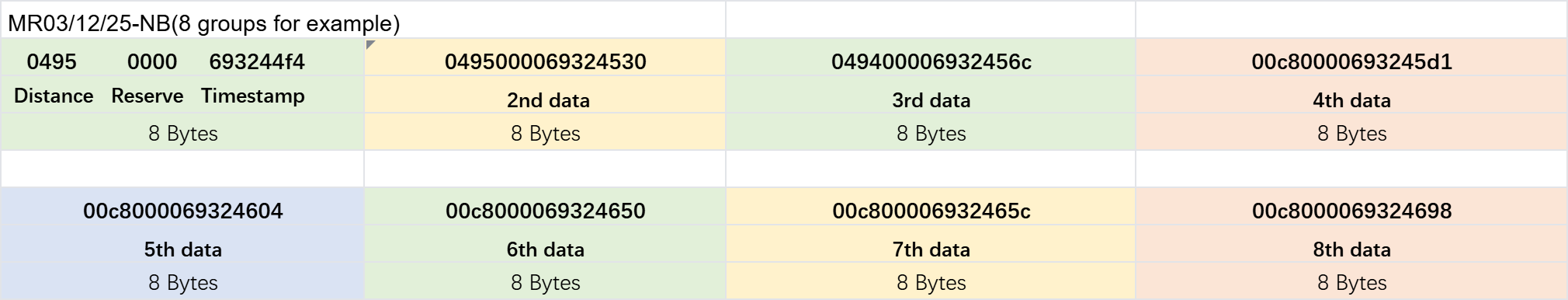
Distance= 0x0495=1173mm
Reserve =0x0000
Unix time is 0x693244f4 =1764902132s=25/12/5 02:35:00
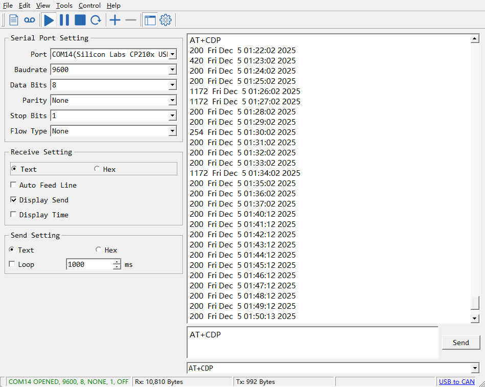
2.8 Example Query saved historical records
- AT Command: AT+CDP
This command can be used to search the saved history, recording up to 32 groups of data, each group of historical data contains a maximum of 100 bytes.
2.9 Uplink log query
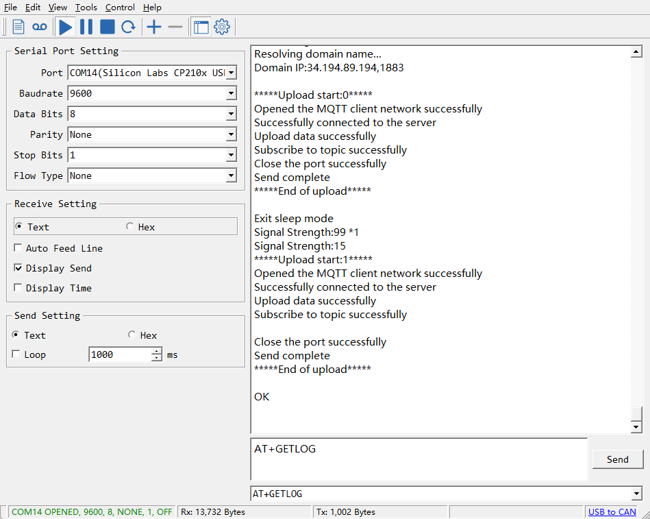
- AT Command: AT+GETLOG
This command can be used to query upstream logs of data packets.
2.10 Scheduled domain name resolution
This command is used to set up scheduled domain name resolution.
AT Command:
- **AT+DNSTIMER=XX **// Unit: hour
After setting this command, domain name resolution will be performed regularly.
2.11 Set the QoS level
This command is used to set the QoS level of MQTT.
AT Command:
- **AT+MQOS=xx **// 0~2
Downlink command: 0x07
Format: Command Code (0x07) followed by 1 byte.
Ex1: Downlink payload: 0x0700 // AT+MQOS=0
Ex2: Downlink payload: 0x0701 // AT+MQOS=1
2.12 Set the downlink debugging mode
Feature: Enable or disable downlink debugging mode. (Since TE platform update, the platform version selection is no longer needed; only downlink debugging can be toggled.)
AT command: AT+DOWNTE
| Command Example | Function/Parameters | Response/Explanation |
|---|---|---|
| AT+DOWNTE=? | Get current Settings | 0,0 (default) OK |
| AT+DOWNTE=0,a | a: Enable/Disable downlink debugging | 0: Disable downlink debugging mode. 1: Enable downlink debugging mode (users can view original downlink messages). |
(Note: The first parameter is fixed to 0 and only the second parameter is configurable.)
Example:
- AT+DOWNTE=0,1 → Enable downlink debugging mode.
- AT+DOWNTE=0,0 → Disable downlink debugging mode.
**Downlink Command: **
No downlink commands for feature
2.13 Domain name resolution settings
Feature: Set dynamic domain name resolution IP.
AT command: AT+BKDNS
| Command Example | Function/Parameters | Response/Explanation |
|---|---|---|
| AT+BKDNS=? | Get current Settings | 0,0,NULL (default) OK |
AT+BKDNS=a,b,c | a: Enable/Disable dynamic domain name resolution. | 1: Disable dynamic domain name update. The ip address will be saved after the domain name is resolved, if the next domain name resolution fails, the last saved ip address will be used. 2: Enable dynamic domain name update. The ip address will be saved after domain name resolution, if the next domain name resolution fails, the last saved ip address will be used, and the domain name resolution will be updated regularly according to the time set by the customer. |
| b: Set the time to update the domain name resolution at regular intervals. | Unit: hour | |
| c: Set the IP address manually. | The format is the same as AT+SERVADDR. If domain name resolution fails, this ip address will be used directly, if domain name resolution succeeds, parameter c will be updated to the successfully resolved IP address. |
Example:
- AT+BKDNS=1,0 // Dynamic domain name resolution is disabled.
- AT+BKDNS=2,1 // The dynamic domain name resolution function is enabled and the automatic update time is set to 1 hour.
- AT+BKDNS=2,4,3.69.98.183,1883 // The dynamic domain name resolution function is enabled and the automatic update time is set to 4 hour, and manually set the ip address, if the domain name failed to resolve, it will directly use this ip to communicate. When the next domain name resolution is successful, it will be updated to the ip address of the successful resolution.
**Downlink Command: **
No downlink commands for feature
2.14 Set CoAP option
This command sets the connection parameters of the COAP.
AT command:
- AT+URI1 // CoAP option name, CoAP option length, "CoAP option value"
- AT+URI2 // CoAP option name, CoAP option length, "CoAP option value"
- AT+URI3 // CoAP option name, CoAP option length, "CoAP option value"
- AT+URI4 // CoAP option name, CoAP option length, "CoAP option value"
Example:
- AT+URI1=11,38,"i/faaa241f-af4a-b780-4468-c671bb574858"
2.15 Calibration Command
Feature: When data deviates from the reference standard, users can reduce display errors by adjusting the"correction value."The correction value can be modified within the range of 0-1000. For example, if the displayed value is 100 units too low, we can correct it by adding 100 to the sampled data using this command: 01 06 00 6B 00 64 F9 FD. In the command, 100 corresponds to hexadecimal 0x64. To reduce the value, set a negative number, such as -100, which corresponds to hexadecimal FF 9C. The calculation is 100 - 65535 = 65435, converted to hexadecimal as 0x FF 9C.
AT Command:
| Command Example | Function | Response |
|---|---|---|
| AT+RSWRITE= 0106006B0064F9FD | Set the sensor's calibration value to 100. Range : no more than 10 bytes | AT+RSWRITE=0106006B0064F9FD OK return:01 06 00 6b 00 64 f9 fd |
| AT+RSWRITE= 0103006B0001F5D6 | Retrieve the current calibration value for the radar sensor | AT+RSWRITE=0103006B0001F5D6 OK return:01 03 02 00 64 b9 af |
Eg: Send command 0106006B0064F9FD to Radar Sensor
AT+RSWRITE=0106006B0064F9FD
Downlink Command:
- 0xE20106006B0064F9FD Same as: AT+RSWRITE=0106006B0064F9FD
Note:
- Unable to retrieve the calibration value for the current sensor setting via the downlink: 0103006B0001F5D6
2.16 Print last few data entries
Feature: Print the last few data entries
AT command: AT+PLDTA
| Command Example | Response |
|---|---|
| AT+PLDTA=5 Print last 5 entries | Stop Tx events when read sensor data 1 25/12/5 01:56:51 distance=200 2 25/12/5 01:57:51 distance=241 3 25/12/5 01:58:51 distance=200 4 25/12/5 01:59:51 distance=200 5 25/12/5 02:00:51 distance=200 Start Tx events OK |
**Downlink Command: **
No downlink commands for feature
2.17 Print data entries base on page
Feature: Print the sector data from start page to stop page.
AT command: AT+PDTA
| Command Example | Response |
|---|---|
| AT+PDTA=1,1 Print page 1 to 1 | Stop Tx events when read sensor data 8028A00 25/12/5 01:01:24 distance=446 8028A08 25/12/5 01:02:24 distance=200 8028A10 25/12/5 01:03:24 distance=200 8028A18 25/12/5 01:04:24 distance=200 8028A20 25/12/5 01:05:24 distance=200 8028A28 25/12/5 01:06:24 distance=200 8028A30 25/12/5 01:07:24 distance=200 8028A38 25/12/5 01:08:24 distance=200 8028A40 25/12/5 01:09:24 distance=200 8028A48 25/12/5 01:10:24 distance=200 8028A50 25/12/5 01:11:24 distance=200 8028A58 25/12/5 01:12:44 distance=547 8028A60 25/12/5 01:13:24 distance=252 8028A68 25/12/5 01:16:02 distance=200 8028A70 25/12/5 01:17:02 distance=200 8028A78 25/12/5 01:18:02 distance=200 Start Tx events OK |
**Downlink Command: **
No downlink commands for feature
2.18 Clear Flash Record
Feature: Clear flash storage for data log feature.
AT command: AT+CLRDTA
| Command Example | Function | Response |
|---|---|---|
| AT+CLRDTA | Clear date record | Stop Tx events,Please wait for the erase to complete Clear all stored sensor data... Start Tx events OK |
Downlink Command: 0x32
- Example: 0x32 00 // Same as AT+CLRDTA
3. Configure MR-03/12/25-NB/NS
3.1 Configure Methods
MR-03/12/25-NB/NS supports below configure method:
-
AT Command via Bluetooth Connection (Recommended): BLE Configure Instruction.
-
AT Command via UART Connection : See UART Connection.
3.2 Serial Access Password
After the Bluetooth or UART connection is successful, use the Serial Access Password to enter the AT command window.
The label on the box of the node will print the initial password: AT+PIN=xxxxxx, and directly use the six-digit password to access the AT instruction window.
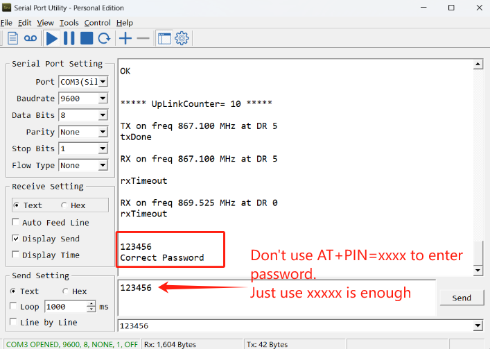
If you need to change the password, use AT+PWORD=xxxxxx (6 characters), NB nodes only support lowercase letters.
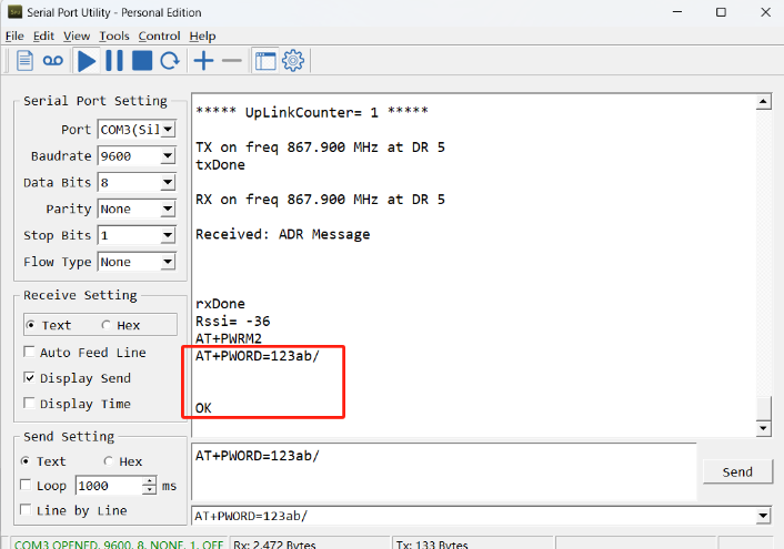
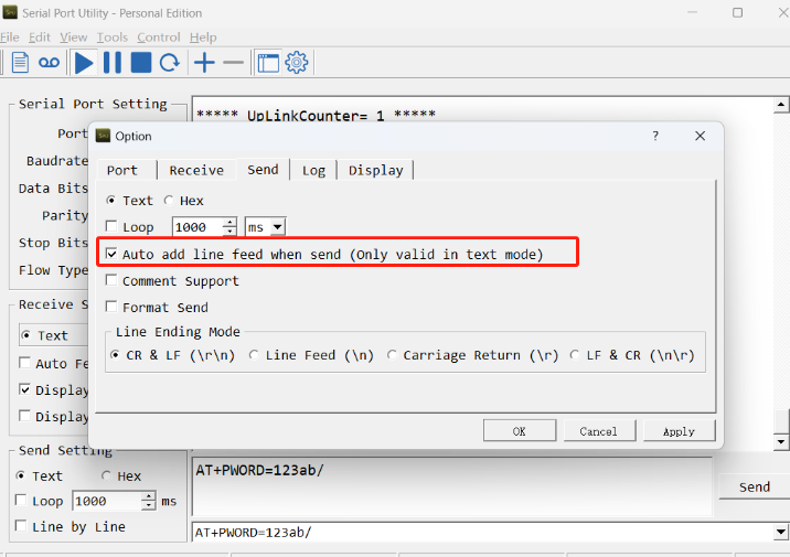
Note: After entering the command, you need to add a line break, and you can also set automatic line breaks in the Bluetooth tool or UART connection tool.
3.3 AT Commands Set
AT+<CMD>? : Help on <CMD>
AT+<CMD> : Run <CMD>
AT+<CMD>=<value> : Set the value
AT+<CMD>=? : Get the value
AT : Attention
AT? : Short Help
ATZ : MCU Reset
AT+TDC : Application Data Transmission Interval
AT+CFG : Print all configurations
AT+CFGMOD : Working mode selection
AT+DEUI : Get or set the Device ID
AT+INTMOD : Set the trigger interrupt mode
AT+5VT : Set extend the time of 5V power
AT+PRO : Choose agreement
AT+RXDL : Extend the sending and receiving time
AT+DNSCFG : Get or Set DNS Server
AT+GETSENSORVALUE : Returns the current sensor measurement
AT+NOUD : Get or Set the number of data to be uploaded
AT+CDP : Read or Clear cached data
AT+ALARMC : Set alarm of distance
AT+SERVADDR : Server Address
MQTT Management
AT+CLIENT : Get or Set MQTT client
AT+UNAME : Get or Set MQTT Username
AT+PWD : Get or Set MQTT password
AT+PUBTOPIC : Get or Set MQTT publish topic
AT+SUBTOPIC : Get or Set MQTT subscription topic
Information
AT+FDR : Factory Data Reset
AT+PWORD : Serial Access Password
AT+LDATA : Get the last upload data
AT+CDP : Read or Clear cached data
4. Battery & Power Consumption
MR-03/12/25-NB use ER26500 + SPC1520 battery pack and MR-03/12/25-NS use 3000mAh Recharable Battery with Solar Panel. See below link for detail information about the battery info and how to replace.
Battery Info & Power Consumption Analyze .
5. Firmware update
User can change device firmware to:
-
Update with new features.
-
Fix bugs.
Firmware and changelog can be downloaded from : Firmware download link
Methods to Update Firmware:
-
(Recommended way) OTA firmware update via BLE: Instruction.
-
Update through UART TTL interface : Instruction.
6. FAQ
6.1 How can I access t BC660K-GL AT Commands?
User can access to BC660K-GL directly and send AT Commands.
6.2 How to configure the certificate?
User can can refer to this description to configure the certificate
6.3 Why is there no LED response when I press the button on the solar panel model?
If the LED does not light up when you press the button, it may be because the battery has entered protection mode.
Solution: To reactivate the battery, simply expose the solar panel to direct sunlight. For more details, please refer to: Battery Protection State (Apply to Solar Panel + Li-ion battery)
7. Order Info
Part Number: MR-XX-NB-YY or MR-XX-NS-YY
XX: Measure Range, options: 03: 3 meters; 12: 12 meters; 25: 25 meters.
YY:
-
GE: General version ( Exclude SIM card)
-
1T: with 1NCE * 10 years 500MB SIM card and Pre-configure to ThingsEye server
8. Packing Info
Package Includes:
-
MR-XX-NB or MR-XX-NS NB-IoT Microwave Radar distance sensor x 1
-
External antenna x 1
Dimension and weight:
-
Device Size: 13.0 x 5 x 4.5 cm
-
Device Weight: 150g
-
Package Size / pcs : 14.0 x 8x 5 cm
-
Weight / pcs : 180g
9. Support
-
Support is provided Monday to Friday, from 09:00 to 18:00 GMT+8. Due to different timezones we cannot offer live support. However, your questions will be answered as soon as possible in the before-mentioned schedule.
-
Provide as much information as possible regarding your enquiry (product models, accurately describe your problem and steps to replicate it etc) and send a mail to Support@dragino.cc.
0