BH01-NB/NS – BLE to NB-IoT Hub User_Manual
BH01-NB/NS – BLE to NB-IoT Hub User_Manual
1. Introduction
1.1 What is BH01-NB/NS BLE to LoRaWAN Hub
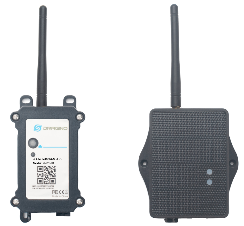
Dragino BH01-NB/NS BLE to LoRaWAN Hub is an edge communication node device designed for loT applications. It uses the BLE Bluetooth module to periodically scan and collect data from surrounding Bluetooth temperature and humidity sensors (such as BCN02, iBeasons or third-party BLE sensors), and then uses the via NB-IoT network* to transmit the data over long distances to the cloud platform, achieving seamless connection between Bluetooth devices and low-power wide area networks.
BH01-NB/NS is a BLE to LoRaWAN Hub which can turn BLE devices to NB-IoT devices. This feature can help system intergrator has widely choice in sensor selection and simplify the network structure.
It is suitable for cold chain warehouse monitoring, smart agricultural environment monitoring, asset tracking and urban infrastructure health management.It combines the fexibility of Bluetooth and the wide coverage of NB-IoT . Compared with wifi connection, it can siginifcantly reduce the deployment cost of the Internet of Things.
BH01-NB/NS supports different uplink methods include TCP, MQTT, UDP, MQTTs or CoAP for different application requirement. and Support Uplinks to various IoT Servers.
BH01-NB/NS is powered by 8500mA Li/SOCl2 battery or solar panel with Li-ion battery for long term use.
*make sure you have NB-IoT coverage locally.
1.2 Features
- NB-IoT Bands: B1/B2/B3/B4/B5/B8/B12/B13/B17/B18/B19/B20/B25/B28/B66/B70/B85 @H-FDD
- Ultra-low power consumption
- Data collcetion: Bluetooth tags monitor environmental parameters in real time and upload data to the Hub via BLE protocol
- Combines BLE's short-range precision with NB-IoT's Long range transmission
- Support Bluetooth v5.1 remote configure and update firmware
- Uplink on periodically
- Downlink to change configure
- 8500mAh Li/SOCl2 Battery (BH01-NB)
- Solar panel + 3000mAh Li-ion battery (BH01-NS)
- Nano SIM card slot for NB-IoT SIM
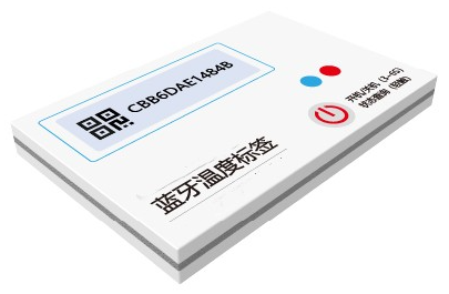
1.3 Bluetooth Sensor Tag Specifcation
DR-TAH02:
- Bluetooth version: Bluetooth LE 5.1 protocol
- Shell material: PET composite plastic bag (heat sealed)
- Temperature range: -40°C ~ +85°C, ±0.3°C
- Waterproof level: IP67
- Battery capacity: 600mAh
- Working temperature: -40°C ~ +60°C
- Battery specifcation: CR2450
- Data storage: 512 records
- Battery life: 3 years (varies with the transmission powerand broadcast
- frequency settings)
- Transmit power: -19.5dBm ~ +2.5dBm (confgurable)
- Broadcast frequency: 500ms (confgurable)
- Sampling frequency: 5min/time (confgurable)
- Broadcast power consumption: 22uA (varies with the transmission
- power and broadcast frequency settings)
- Broadcast mode: Custom Sensor broadcast
- Broadcast distance Distance: 100m (varies with thetransmission
- power setting)
- Confguration APP: EW_smartconfig (Android Click to download )
- Configuration Method:Method
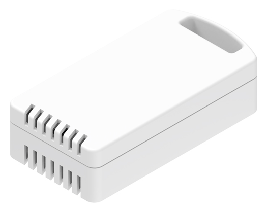
DR-ES01:
- Bluetooth version: Bluetooth LE 5.3 protocol
- Casing material: PC material
- Temperature range: 0°C ~ +85°C, ±0.2°C
- Waterproof level: IP65
- Battery capacity: 1100mAh
- Working temperature: 0°C ~ +85°C
- Battery specifcation: AAA LR03 x2
- Battery life: 3 years (varies with the transmission powerand broadcast
- frequency settings)
- Transmit power: -20dBm ~ +4dBm (confgurable)
- Broadcast frequency: 1000ms (confgurable)
- Humidity range: 0~100%RH, ±2%RH
- Broadcast power consumption: 34uA (varies with the transmission
- power and broadcast frequency settings)
- Supported system: Android 4.3 / IOS7.0 and above
- Broadcast mode: Custom Sensor broadcast
- Broadcast distance Distance: 100m (varies with thetransmission
- power setting)
- Confguration APP: nRF connect (Android / IOS)
- Supported system: Android 4.3 / IOS7.0 and above
- Configuration Method:Method
1.4 Specification
Common DC Characteristics:
- Supply Voltage: Built-in Battery , 2.5v ~ 3.6v
- Operating Temperature: -40 ~ 85°C
NB-IoT Spec:
NB-IoT Module: BC660K-GL
Support Bands:
- B1 @H-FDD: 2100MHz
- B2 @H-FDD: 1900MHz
- B3 @H-FDD: 1800MHz
- B4 @H-FDD: 2100MHz
- B5 @H-FDD: 860MHz
- B8 @H-FDD: 900MHz
- B12 @H-FDD: 720MHz
- B13 @H-FDD: 740MHz
- B17 @H-FDD: 730MHz
- B18 @H-FDD: 870MHz
- B19 @H-FDD: 870MHz
- B20 @H-FDD: 790MHz
- B25 @H-FDD: 1900MHz
- B28 @H-FDD: 750MHz
- B66 @H-FDD: 2000MHz
- B70 @H-FDD: 2000MHz
- B85 @H-FDD: 700MHz
Battery:
- Li/SOCI2 un-chargeable battery
- Capacity: 8500mAh
- Self Discharge: <1% / Year @ 25°C
- Max continuously current: 130mA
- Max boost current: 2A, 1 second
Power Consumption
- STOP Mode: 10uA @ 3.3v
- Max transmit power: 350mA@3.3v
1.5 Sleep mode and working mode
**Deep Sleep Mode: **Sensor doesn't have any NB-IoT activate. This mode is used for storage and shipping to save battery life.
Working Mode: In this mode, Sensor will work as NB-IoT Sensor to Join NB-IoT network and send out sensor data to server. Between each sampling/tx/rx periodically, sensor will be in IDLE mode), in IDLE mode, sensor has the same power consumption as Deep Sleep mode.
1.6 Button & LEDs
| Behavior on ACT | Function | Action |
|---|---|---|
| Send an uplink | If sensor has already attached to NB-IoT network, sensor will send an uplink packet, blue led will blink once. Meanwhile, BLE module will be active and user can connect via BLE to configure device. | |
| Active Device | Green led will fast blink 5 times, device will enter OTA mode for 3 seconds. And then start to attach NB-IoT network. Once sensor is active, BLE module will be active and user can connect via BLE to configure device, no matter if device attach NB-IoT network or not. | |
| Deactivate Device | Red led will solid on for 5 seconds. Means device is in Deep Sleep Mode. |
Note: When the device is executing a program, the buttons may become invalid. It is best to press the buttons after the device has completed the program execution.
1.7 BLE connection
BH01-NB/NS supports BLE remote configure.
BLE can be used to configure the parameter of sensor or see the console output from sensor. BLE will be only activate on below case:
- Press button to send an uplink
- Press button to active device.
- Device Power on or reset.
If there is no activity connection on BLE in 60 seconds, sensor will shut down BLE module to enter low power mode.
1.8 Pin Definitions
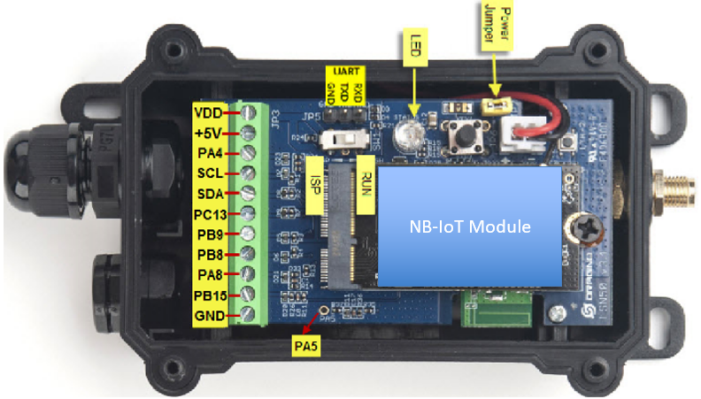
1.8.1 Jumper JP2
Power on Device when put this jumper.
1.8.2 BOOT MODE / SW1
1) ISP: upgrade mode, device won't have any signal in this mode. but ready for upgrade firmware. LED won't work. Firmware won't run.
2) Flash: work mode, device starts to work and send out console output for further debug
1.8.3 Reset Button
Press to reboot the device.
1.8.4 SIM Card Direction
See this link. How to insert SIM Card.
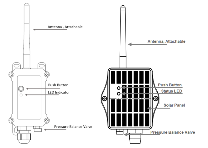
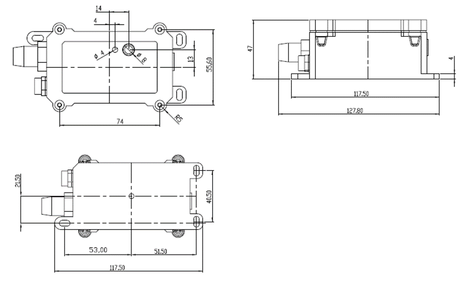
1.9 Mechanical
1.9.1 for NB version
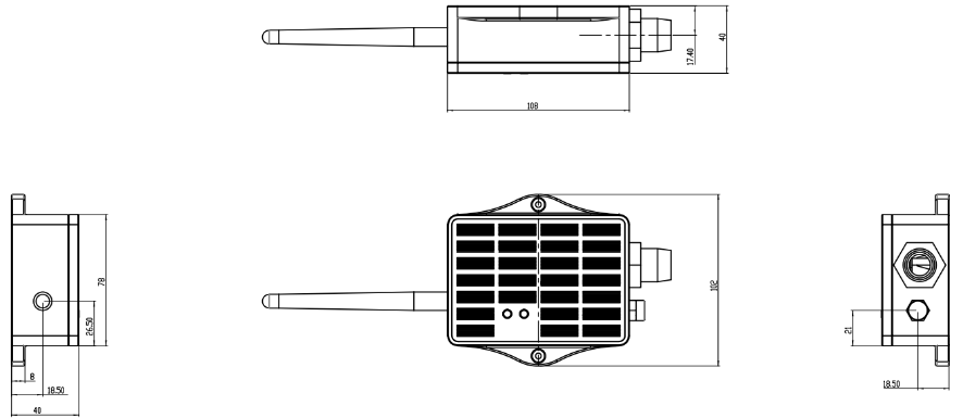
1.9.2 for NS version
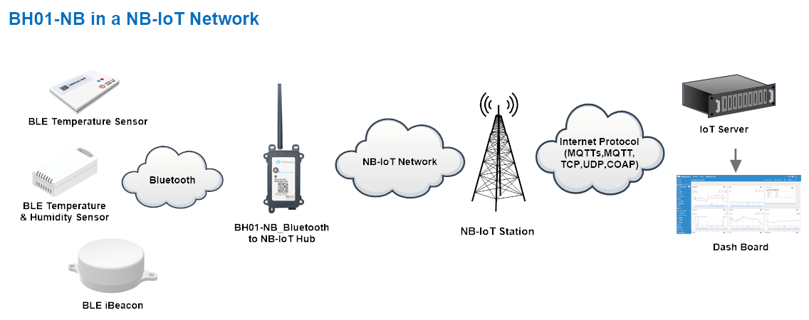
2. Use BH01-NB to communicate with IoT Server
2.1 Send data to IoT server via NB-IoT network
The BH01-NB is equipped with a NB-IoT module, the pre-loaded firmware in BH01-NB will get environment data from sensors and send the value to local NB-IoT network via the NB-IoT module. The NB-IoT network will forward this value to IoT server via the protocol defined by BH01-NB.
Below shows the network structure:
There are two version: -GE and -1T version of BH01-NB.
GE Version: This version doesn't include SIM card or point to any IoT server. User needs to use AT Commands to configure below two steps to set BH01-NB send data to IoT server.
-
Install NB-IoT SIM card and configure APN. See instruction of Attach Network.
-
Set up sensor to point to IoT Server. See instruction of Configure to Connect Different Servers.
Below shows result of different server as a glance.
| Servers | Dash Board | Comments |
|---|---|---|
| Node-Red | 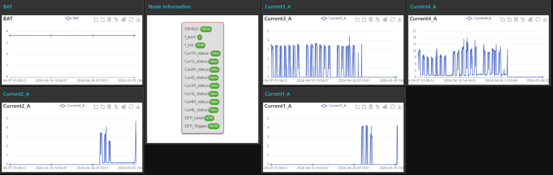 | |
| DataCake | 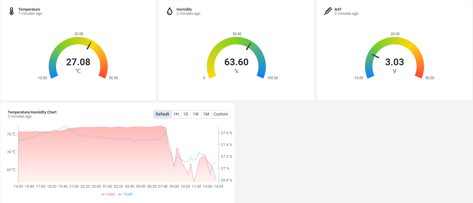 | |
| Tago.IO | ||
| General UDP | Raw Payload. Need Developer to design Dash Board | |
| General MQTT | Raw Payload. Need Developer to design Dash Board | |
| ThingsBoard | 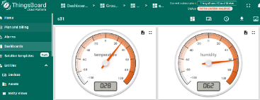 |
1T Version: This version has 1NCE SIM card pre-installed and configure to send value to ThingsEye. User Just need to select the sensor type in ThingsEyeand Activate BH01-NB and user will be able to see data in ThingsEye. See here for ThingsEye Config Instruction.
2.2 Payload Types
To meet different server requirement, BH01-NB supports different payload type.
Includes:
-
General JSON format payload. (Type=5)
-
HEX format Payload. (Type=0)
-
ThingsBoard Format. (Type=3)
User can specify the payload type when choose the connection protocol. Example:
AT+PRO=1,0 // Use COAP Connection & hex Payload
AT+PRO=1,5 // Use COAP Connection & Json Payload
AT+PRO=2,0 // Use UDP Connection & hex Payload
AT+PRO=2,5 // Use UDP Connection & Json Payload
AT+PRO=3,0 // Use MQTT Connection & hex Payload
**AT+PRO=3,5 ** // Use MQTT Connection & Json Payload
AT+PRO=4,0 // Use TCP Connection & hex Payload
**AT+PRO=4,5 ** // Use TCP Connection & Json Payload
2.3 Uplink Payload
2.3.1 General Json Format(Type=5)
This is the General Json Format. As below:
{"IMEI":"863663062798971","IMSI":"460087023300063","Model":"BH01-NB","Dev_Bat":3.38,"Signal":21,"Time":"2026/01/30 07:45:51","B_01":["80eccccf6745",10007,28226,-61,-63],"B_02":["80eccccf64f1",10007,27942,-61,-80],"B_03":["80eccccf6b7c",10007,27161,-61,-73],"B_04":["80eccccf6537",10007,28787,-61,-90],"B_05":["80eccccf6549",10007,28744,-61,-80],"B_06":["80eccccf6542",10007,28766,-61,-77]}
Example:
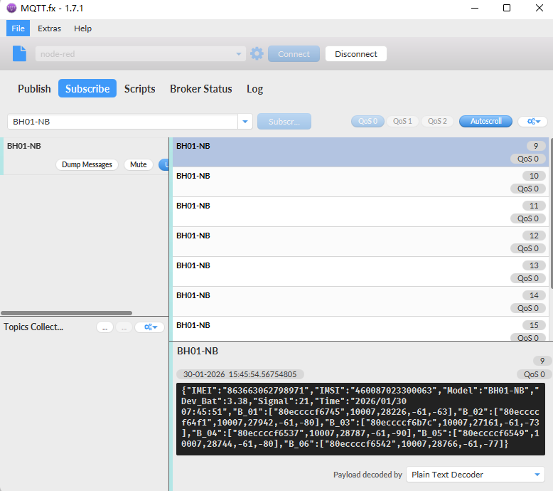
Notice, from above payload:
- Dev_Bat, Signal, time & Bluetooth beacon(Transmit up to 40 beacon data sets)are the value at uplink time.
Transmission Protocol Byte Limit (JSON Format):
- When using UDP as the transmission protocol, if the upload byte count exceeds 2048 bytes, it will be fragmented for upload.
- When using TCP as the transmission protocol, if the upload byte count exceeds 2048 bytes, it will be fragmented for upload.
- When using MQTT as the transmission protocol, if the upload byte count exceeds 1460 bytes, it will be fragmented for upload.
- When using the COAP transport protocol, if the number of bytes in the upload exceeds 1024 bytes, the upload will be fragmented.
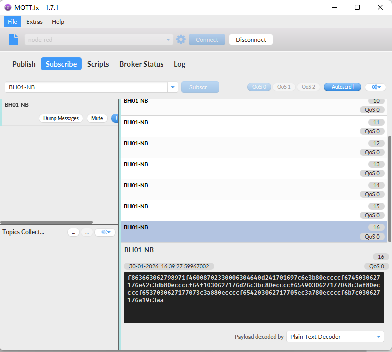
2.3.2 HEX format Payload(Type=0)
This is the HEX Format. As below:
f863663062798971f46008702330006304640d241701697c6e3b80eccccf6745030627176e42c3db80eccccf64f1030627176d26c3bc80eccccf6549030627177048c3af80eccccf6537030627177073c3a880eccccf654203062717705ec3a780eccccf6b7c030627176a19c3aa

Version:
These bytes include the hardware and software version.
Higher byte: Specify Sensor Model: 0x04 for BH01-NB & BH01-NS
Lower byte: Specify the software version: 0x64=100, means firmware version 1.0.0
BAT (Battery Info):
Ex1: 0x0D24 = 3364mV
Signal Strength:
NB-IoT Network signal Strength.
Ex1: 0x17 = 23
0 -113dBm or less
1 -111dBm
2...30 -109dBm... -53dBm
31 -51dBm or greater
99 Not known or not detectable
Bluetooth Beacon Data:
Note:
1. This payload transmits data based on Bluetooth beacons scanned by the node, with the node capable of scanning data from up to 40 beacons.
2.Transport Protocol Byte Limits:
When using the UDP transport protocol, if the uplink byte count exceeds 1024 bytes, the data will be fragmented for transmission.
When using the TCP transport protocol, if the uplink byte count exceeds 1024 bytes, the data will be fragmented for transmission.
When using the MQTT transport protocol, if the upload byte count exceeds 730 bytes, it will be fragmented for upload;
When using the COAP transport protocol, if the upload byte count exceeds 1024 bytes, it will be fragmented for upload;
For example:
80eccccf6745030627176e42c3db 80eccccf64f1030627176d26c3bc 80eccccf6549030627177048c3af 80eccccf6537030627177073c3a8 80eccccf654203062717705ec3a7 80eccccf6b7c030627176a19c3aa
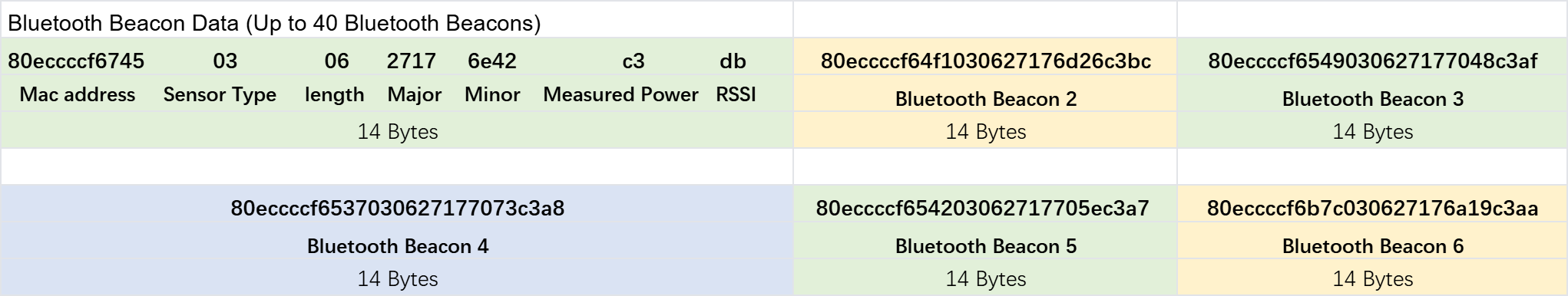
For example: 80eccccf6745030627176e42c3db
Mac address: 0x80eccccf6745
Sensor Tpye: 0x03
Data_length: 0x06
Major: 0x2717
Minor: 0x6e42
Measured Power: 0xc3
RSSI: 0xDB
2.4 Parameter Description
BH01-NB/NS has different working mode for the connections of different type of sensors. This section describes these modes. Use can use the AT Command:
AT+MODEL=abcdefgh to set BH01-NB/NS to different working modes.
For example:
AT+MODEL=030500190b0004ff4c000215011223344556 (turn on scanning Bluetooth ibeacon beacons)
Parameter a = 0x03: Set the scanning mode to Bluetooth ibeacon beacons.
Parameter b = 0x05: Set the intercepted data length to 5.
Parameter c = 0x00: Set the intercepted data position to the broadcast packet.
Parameter d = 0x19: Set the intercepted data starting position 25.
Parameter e = 0x0b: Set the filter data length to 11.
Parameter f = 0x00: Set the filter data position to the scan reply response packet.
Parameter g = 0x04: Set the filter data starting position 4.
Parameter h = 0xff4c000215011223344556: Set the filter data to 0xff4c000215011223344556 (0xff is AD Type).
2.4.1 Parameter a: type mode
Modes 4 to 16 (a = 0x04 to 0x16) are user-defined scanning device modes based on the sensor used.
Mode 1 (a = 0x01): Bluetooth Temperature Tag (TAH02) mode
| Mac address (6 bytes) | 0xEE 3B 14 28 32 D1 | / |
| Sensor type (1 byte) | 0x01 | Temperature sensor |
| Sensor data length (1 byte) | 0x04 | Data length |
| Temperature (2 bytes) | 0x2701 | Temperature: 29.5℃ |
| Battery (1 byte) | 0x64 | Battery: 100% |
| RSSI (1 byte) | 0xC3 | 1 meter output power: -61db |
AT+MODEL=0104: Start scanning Bluetooth temperature tag (TAH02)mode.
AT+MODEL=0100: Turn off scanning for Bluetooth temperature tags (TAH02)mode.
Mode 2 (a = 0x02): Bluetooth temperature and humidity (ES01) mode
| Mac address (6 bytes) | 0xEE 3B 14 28 32 D1 | / |
| Sensor type (1 byte) | 0x02 | Temperature and humidity sensor |
| Sensor data length (1 byte) | 0x05 | Data length |
| Humidity (1 byte) | 0x4C | THumidity: 76% |
| Temperature (2 bytes) | 0x2701 | Temperature: 29.5℃ |
| Battery (1 byte) | 0x64 | Battery: 100% |
| RSSI (1 byte) | 0xC3 | 1 meter output power: -61db |
AT+MODEL=0205: Enable Bluetooth temperature and humidity scanning (ES01)mode.
AT+MODEL=0200: Disable Bluetooth temperature and humidity scanning (ES01)mode.
Mode 3 (a = 0x03): Bluetooth ibeacon mode
| Mac address (6 bytes) | 0xEE 3B 14 28 32 D1 | / |
|---|---|---|
| Sensor type (1 byte) | 0x03 | ibeacon beacon |
| Sensor data length (1 byte) | 0x06 | Data length |
| Major (2byte) | 0x1122 | / |
| Minor (2byte) | 0x004c | / |
| Measured Power(1byte) | 0x64 | Measured Bluetooth transmission power |
| RSSI (1 byte) | 0xC3 | 1 meter output power: -61db |
AT+MODEL=030500190b0004ff4c000215011223344556: Enable the Bluetooth ibeacon beacon scanning mode.
AT+MODEL=0300: Disable the Bluetooth ibeacon beacon scanning mode.
Mode 4 to 16(a = 0x04 to 0x16): user-defined scanning device mode
Note: Different scanning modes can work at the same time.
If the user needs to scan Bluetooth temperature and humidity (ES01) and Bluetooth Temperature Tag (TAH02) at the same time, then just input the following continuously:
AT+MODEL=0104
AT+MODEL=0205
2.4.2 Parameter b: The effective data length of the interception
b equals 0: indicates that the scanning of the corresponding modes 1 to 16 is canceled.
b is not equal to 0: set the b parameter according to the valid data intercepted by the sensor time.
For example,
in mode 1 (a = 0x01), the default parameter b is 4.
In mode 2 (a = 0x02), the default parameter b is 5.
When it is mode 1 and 2, scanning can be performed after setting the b parameter; the subsequent parameter cdefgh does not need to be set.Mode 1 (a = 0x01): Bluetooth Temperature Tag (TAH02)
In other modes,users need to set the following cdefgh parameters to enable this mode.
2.4.3 Parameter c: intercepted valid data position
c = 0x00: in the broadcast packet
c = 0x01: in the scan reply packet.
Note: Generally:
scan data includes two types: broadcast packets (31 bytes) and scan response packets (31 bytes). There is at least one type of broadcast packet. You can use a mobile phone to scan and obtain the complete scan data.
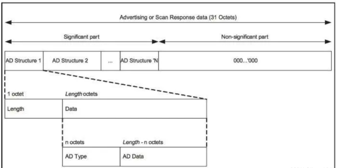
Both the broadcast packet and the scan reply packet are composed of several unit data; the unit data format is length+AD Type+AD Data.
2.4.4 Parameter d: The starting position of the intercepted valid data
The starting position starts from 0.
The broadcast packet and the scan reply packet are two different packets, and the interception should start from 0.
The maximum is no more than 30.
2.4.5 Parameter e: scan and filter data length
The maximum value is 31.
2.4.6 Parameter f: Scan filtered data location
f = 0x00: The data location of the scan filter is in the broadcast packet
f = 0x01: The data location of the scan filter is in the scan reply packet
2.4.7 Parameter g: the starting position of the scanned filtered data
The starting position starts from 0.
The broadcast packet and the scan reply packet are two different packets, and the filtering data should start from 0.
The maximum is no more than 30.
2.4.8 Parameter h: scan filtered data
It is recommended to use data with UUID and Bluetooth names to filter out unnecessary scan data.
Generally, the more scan filter data there is, the less interference can be filtered.
The data from the starting position 0 to the data including the UUID or Bluetooth name part can be used as filter data.
If the user needs to customize, please refer to the following example:
Manufacturers are required to provide Raw data, scanned broadcast packet data, scanned response packet data, valid data, and filtered data.
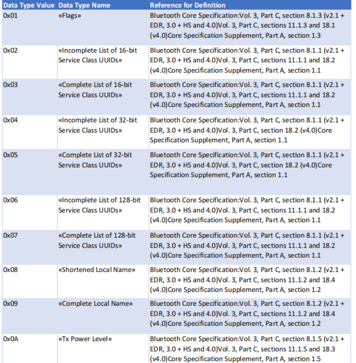
For example: AD Type Reference Table
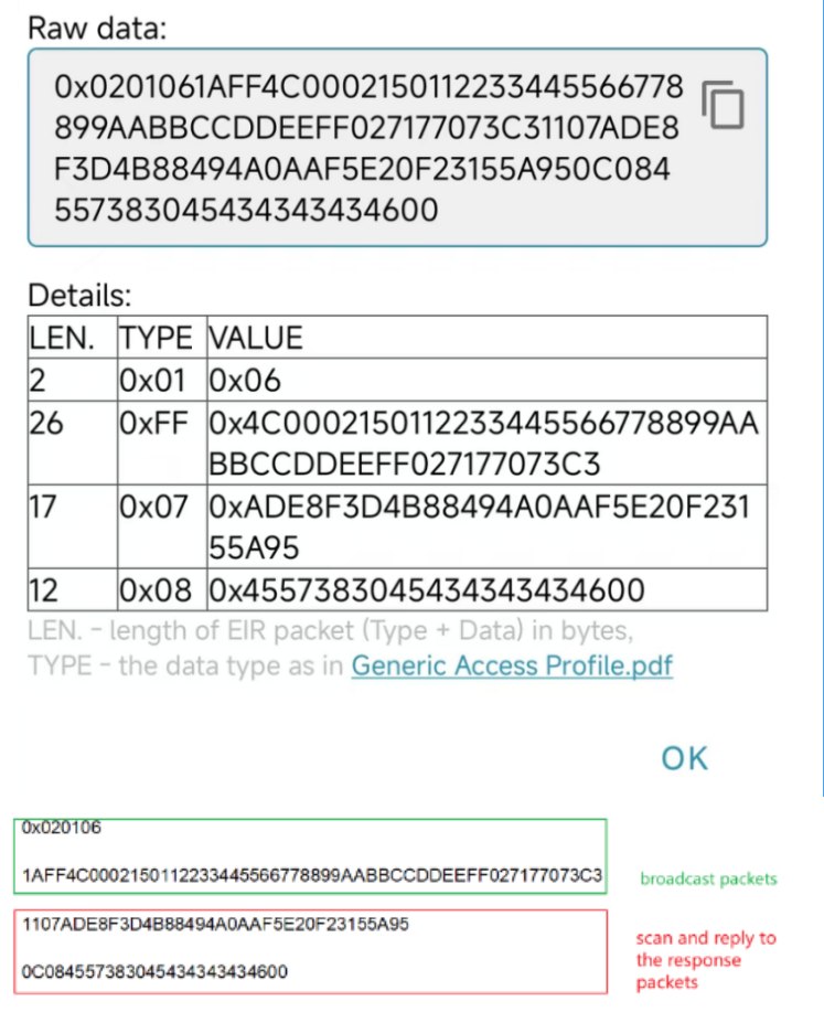
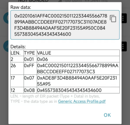
  Assume that the valid data is AD E8 F3 D4 B8 84 94 A0 AA F5 E2 0F 23 15 5A 95

  Assume the filtered data is 1A FF 4C 00 02 15 01 12 23 34 45 56 67 78 89 9A AB BC CD DE EF F0 27 17 70 73 C3

  Raw data analysis:

   0×02 01 06

   Length = 0x02                            AD Type = 0x01

   AD Data = 0x06

   1A FF 4C 00 02 15 01 12 23 34 45 56 67 78 89 9A AB BC CD DE EF F0 27 17 70 73 C3

   Length = 0x1A(26)                 AD Type = 0xFF(This is a custom data type for Bluetooth manufacturers)

   Data =0x4C0002150112233445566778899AABBCCDDEEFF027177073C3

   11 07 AD E8 F3 D4 B8 84 94 A0 AA F5 E2 0F 23 15 5A 95

   Length = 0x11(17)                  AD Type = 0x07 (UUID)

   AD Data = 0xADE8F3D4B88494A0AAF5E20F23155A95

   0C 08 45 57 38 30 45 43 43 43 43 46 00

   Length = 0x0C(12)                  AD Type = 0x08 (Bluetooth Name)

   AD Data = 0x4557383045434343434600

  Analyze valid data:

   AD E8 F3 D4 B8 84 94 A0 AA F5 E2 0F 23 15 5A 95

   Valid data length = 0x10 (16)                               ➡  b = 0x16

   Valid data location = 0x00 (Broadcast Packet)     ➡  c = 0x00

   Valid data starting position = 0x20 (32)              ➡  d = 0x20

  Analyze the filtered data:

  1A FF 4C 00 02 15 01 12 23 34 45 56 67 78 89 9A AB BC CD DE EF F0 27 17 70 73 C3  ➡  h = 1aff4c0002130112233445566778899aabbccddeeff027177073c3

  filtered data length = 0x1B (27)                            ➡  e = 0x1b

  filtered data location = 0x00 (Broadcast Packet)  ➡  f  = 0x00

  filtered data starting position = 0x03                  ➡  g = 0x03

  So the user can set the AT command as:

  AT+MODEL=041600201b00031aff4c0002130112233445566778899aabbccddeeff027177073c3
3. Configure BH01-NB/NS
3.1 Configure Methods
BH01-NB/NS supports below configure method:
-
AT Command via Bluetooth Connection (Recommended): BLE Configure Instruction.
-
AT Command via UART Connection : See UART Connection.
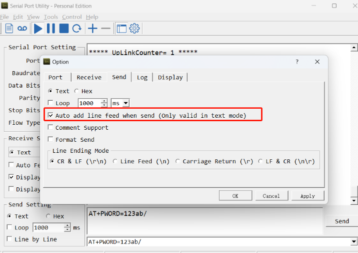
3.2 Serial Access Password
After the Bluetooth or UART connection is successful, use the Serial Access Password to enter the AT command window.
The label on the box of the node will print the initial password: AT+PIN=xxxxxx, and directly use the six-digit password to access the AT instruction window.
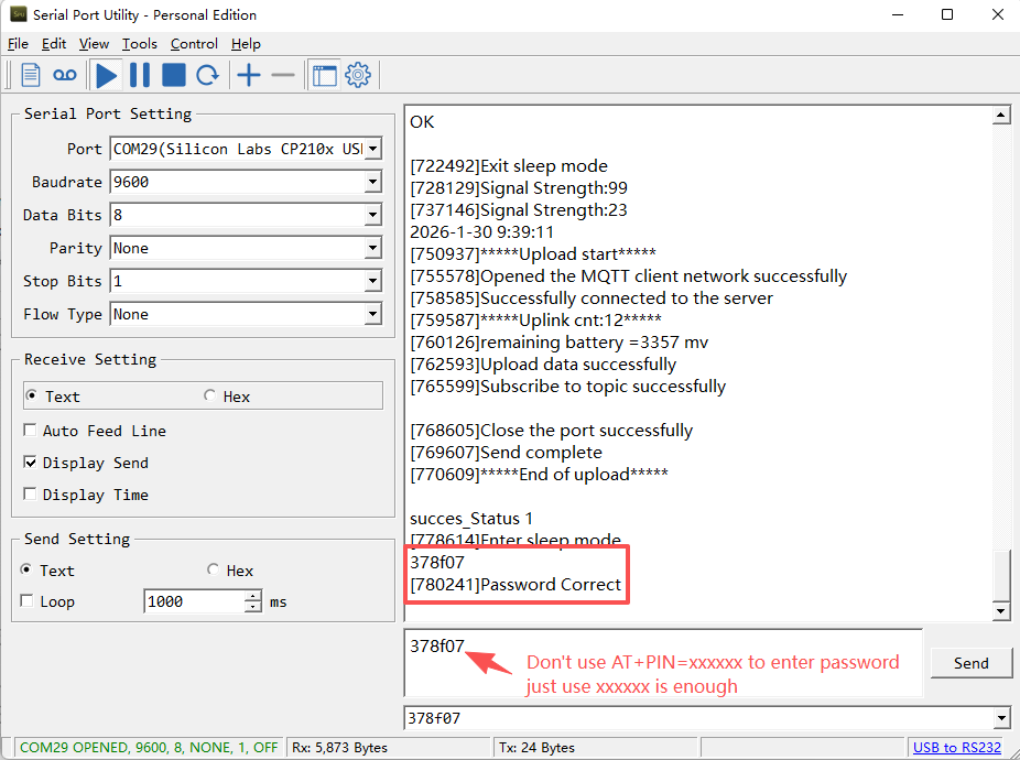
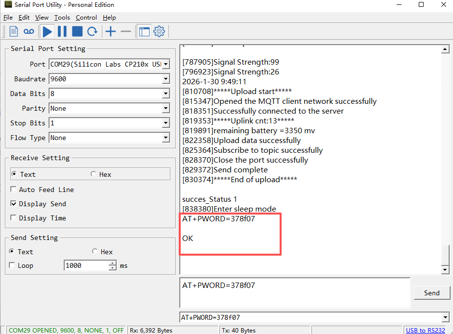
If you need to change the password, use AT+PWORD=xxxxxx (6 characters), -NB nodes only support lowercase letters.
Note: After entering the command, you need to add a line break, and you can also set automatic line breaks in the Bluetooth tool or UART connection tool.
3.3 AT Commands Set
AT+<CMD>? : Help on <CMD>
AT+<CMD> : Run <CMD>
AT+<CMD>=<value> : Set the value
AT+<CMD>=? : Get the value
ATZ : Trig a reset of the MCU
AT+DEUI : Get or set the Device ID
AT+SERVADDR: Get or Set the Server address
AT+TDC : Get or set the application data transmission interval in s
AT+APN : Get or set the APN
AT+PRO : Get or Set usage agreement (1:COAP,2:UDP,3:MQTT,4:TCP)
AT+RXDL : Get or Set the receiving time
AT+GETSENSORVALUE : Returns the current sensor measurement
AT+DNSCFG : Get or Set DNS Server
AT+CSQTIME : Get or Set the time to join the network
AT+BKDNS : Get or Set dynamic domain name resolution IP
AT+SLEEP : Get or Set the sleep mode
AT+DOWNTE: Get or set the conversion between the standard version and 1T version downlinks
AT+FILTERMODEL: Get or set the filtering Bluetooth scanning mode
AT+BLESCANTIME: Get or Set the Bluetooth scan time
AT+TIMEDSEND: Get or Set the timed send time
AT+FILTERRSSI: Get or set the RSSI range of the scanned devicer
MQTT Management
AT+CLIENT : Get or Set the MQTT clientID
AT+UNAME : Get or Set the MQTT Username
AT+PWD : Get or Set the MQTT password
AT+PUBTOPIC: Get or set MQTT publishing topic
AT+SUBTOPIC: Get or set MQTT subscription topic
AT+MQOS : Set the QoS level of MQTT
AT+TLSMOD : Get or Set the TLS mode
COAP Management
AT+URI1: Get or set CoAP option 1
AT+URI2: Get or set CoAP option 2
AT+URI3: Get or set CoAP option 3
AT+URI4: Get or set CoAP option 4
Information
AT+FDR1 : Reset parameters to factory default values except for passwords
AT+FDR : Reset Parameters to Factory Default
AT+CFG : Print all settings
AT+PWORD : Get or set the System password
AT+LDATA : Get the last upload data
AT+GETLOG : Print serial port logs
3.4 Test Uplink and Change Update Interval
By default, Sensor will send uplinks every 2 hours.
User can use below commands to change the uplink interval.
AT Command: AT+TDC
Example: AT+TDC=7200 // Set Update Interval to 7200 seconds
Downlink Commands: 0x01
Format: Command Code (0x01) followed by 3 bytes.
Example: 12 hours= 43200 seconds 43200(D)=0xA8C0(H)
Downlink Payload: `01 00 A8 C0` // AT+TDC=43200, Set Update Interval to 12 hours.
Note: User can also push the button for more than 1 second to activate an uplink.
3.5 Set the receiving time
Feature: Extend the receiving time
AT Command: AT+RXDL
Example: AT+RXDL=1000 // Set the receiving time delay to 1000ms
Downlink Commands: 0x03
Format: Command Code (0x03) followed by 3 bytes.
Example: Downlink Payload: 03 00 03 E8// AT+RXDL=1000
3.6 Reset
Feature: Trig a reset of the MCU.
AT Command: ATZ
Downlink Commands: 0x04FF
3.7 Set the QoS level
This command is used to set the QoS level of MQTT.
AT command:
- **AT+MQOS=xx **// 0~2
Downlink command: 0x07
Format: Command Code (0x07) followed by 1 byte.
Ex1: Downlink payload: 0x0700 // AT+MQOS=0
Ex2: Downlink payload: 0x0701 // AT+MQOS=1
3.8 Set the TLS mode
Refer to this link (MQTT Connection to send data to Tago.io)to use the TLS mode.
AT Command: AT+TLSMOD
**Example 1: ** AT+TLSMOD=0,0 // Disable TLS Mode.
Example 2: AT+TLSMOD=1,0 // No authentication
                 AT+TLSMOD=1,1   // Perform server authentication

                 AT+TLSMOD=1,2   // Perform server and client authentication if requested by the remote server
Downlink command: 0x09
Format: Command Code (0x09) followed by 2 bytes.
Example1: Downlink Payload: 09 00 00// AT+TLSMOD=0,0
Example2: Downlink Payload: 09 01 02// AT+TLSMOD=1,2
3.9 Set the search network time
Feature: Get or Set the time to join the network(unit: minutes).
AT Command: AT+CSQTIME
Example: AT+CSQTIME=10 // Set the search time to 10 minutes.
Downlink command: 0x13
Format: Command Code (0x13) followed by 1 byte.
Example: Downlink Payload: 13 0A// AT+CSQTIME=10
3.10 Factory data reset
Two different restore factory Settings configurations.
AT command:
- **AT+FDR **// Reset Parameters to Factory Default.
- **AT+FDR1 **// Reset parameters to factory default values except for passwords.
**Downlink Command: **
No downlink commands for feature
3.11 Set CoAP option
Feature: Set CoAP option, follow this link to set up the CoaP protocol.
AT command: AT+URI1~AT+URI4
- AT+URI1 // CoAP option name, CoAP option length, "CoAP option value"
- AT+URI2 // CoAP option name, CoAP option length, "CoAP option value"
- AT+URI3 // CoAP option name, CoAP option length, "CoAP option value"
- AT+URI4 // CoAP option name, CoAP option length, "CoAP option value"
Example:
- AT+URI1=11,38,"i/faaa241f-af4a-b780-4468-c671bb574858"
**Downlink Command: **
No downlink commands for feature
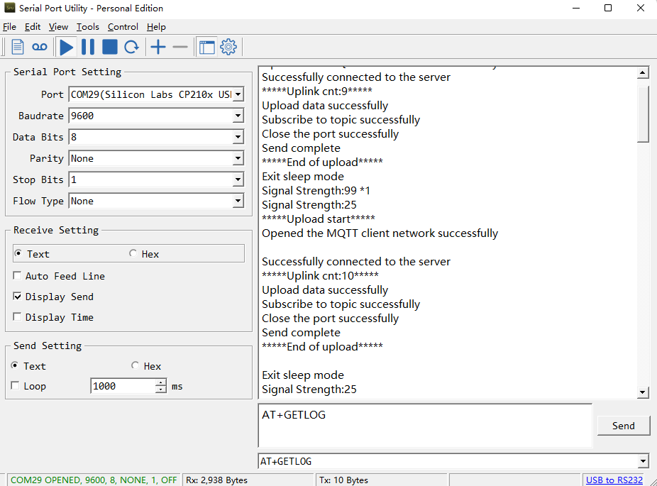
3.12 Uplink log query
AT command: AT+GETLOG
This command can be used to print serial port logs.
**Downlink Command: **
No downlink commands for feature
3.13 Set the downlink debugging mode
Feature: Enable or disable downlink debugging mode. (Since TE platform update, the platform version selection is no longer needed; only downlink debugging can be toggled.)
AT command: AT+DOWNTE
| Command Example | Function/Parameters | Response/Explanation |
|---|---|---|
| AT+DOWNTE=? | Get current Settings | 0,0 (default) OK |
| AT+DOWNTE=0,a | a: Enable/Disable downlink debugging | 0: Disable downlink debugging mode. 1: Enable downlink debugging mode (users can view original downlink messages). |
(Note: The first parameter is fixed to 0 and only the second parameter is configurable.)
Example:
- AT+DOWNTE=0,1 → Enable downlink debugging mode.
- AT+DOWNTE=0,0 → Disable downlink debugging mode.
**Downlink Command: **
No downlink commands for feature
3.14 Domain name resolution settings
Feature: Set static DNS resolution IP address.
AT command: AT+BKDNS
| Command Example | Function/Parameters | Response/Explanation |
|---|---|---|
| AT+BKDNS=? | Get current Settings | 1,0,NULL (default) OK |
AT+BKDNS=a,b,c | a: Enable/Disable static DNS resolution. | 0: Disable static DNS resolution 1: Enable static DNS resolution. The ip address will be saved after the domain name is resolved, if the next domain name resolution fails, the last saved ip address will be used. |
| b: Meaningless. | Set to 0. | |
| c: Set the IP address manually. | The format is the same as AT+SERVADDR. If domain name resolution fails, this ip address will be used directly, if domain name resolution succeeds, parameter c will be updated to the successfully resolved IP address. |
Example:
- AT+BKDNS=0,0,NULL //Disable static DNS resolution.
- AT+BKDNS=1,0,NULL // Enable static DNS resolution.
- AT+BKDNS=1,0,3.69.98.183,1883 //Enable static DNS resolution, if domain name resolution succeeds, the node uses the ip address successfully resolved and saves it to parameter c. If the domain name resolution fails, use the manually set ip address: 3.69.98.183 for communication.
**Downlink Command: **
No downlink commands for feature.
3.15 Commands special design for BH01-NB/NS
These commands only valid for BH01-NB/NS, as below:
3.15.1 Set the Bluetooth scan Time
AT Command: AT+BLESCANTIME
| Command Example | Function | Response |
|---|---|---|
| AT+BLESCANTIME=? | Show current Bluetooth scan time | 7 OK Bluetooth scan time is 7s |
| AT+BLESCANTIME=5 | Set Bluetooth scan time | OK Set Bluetooth scan time to 5 seconds |
Downlink Command: 0x0C
Format: Command Code (0x0C) followed by 1 byte of time value.
If the downlink payload = 0C05, it means setting the Bluetooth scan time to 0x05 = 5 (S) and the type code is 06.
- Example: Downlink Payload: 0C07 // Set Transmit Interval (BLESCANTIME) = 7 seconds
3.15.2 Timed Uplink Transmission (AT+TIMEDSEND)
The AT+TIMEDSEND command allows users to configure BH01 devices to scan iBeacons and send uplink data at specified times, for example every hour on the clock (10:00, 11:00, etc.).
| Command Example | Function | Response |
|---|---|---|
| AT+TIMEDSEND=? | Show start timing parameters | 1,0,60 OK |
| AT+TIMEDSEND=a,b,c | Set the timing parameters | OK |
Parameters:
- a: 0 = Disable timed transmission, 1 = Enable timed transmission.
- b: Time offset (in seconds, 0–3599) from the next full hour when scanning will start.
- c: Uplink data interval (TDC) in minutes, range 1–255.
Example: AT+TIMEDSEND=1,10,60
→ Enable timed transmission. Start scanning at 10 seconds past every full hour, then uplink every 60 minutes.
If the current time is 15:15, the BH01 will start scanning at 16:00:10, then at 17:00:10, 18:00:10, and so on. After each scan (lasting BLESCANTIME), all BLE information will be uploaded.
Downlink Command
- Command Code: 0x0D
- Format: 0x0D + 1 byte (enable/disable) + 3 bytes (time value).
Example: 0D01000030
= Equivalent to AT+TIMEDSEND=1,10,60.
Important Notes
- If multiple BH01 devices are configured with the same parameters, they may uplink simultaneously, causing network collisions and packet loss.
- To avoid conflicts, configure parameter b with different offsets (e.g., 5s, 10s, 15s…) so each device transmits at slightly different times.
3.15.3 Set Workmode
Feature: Switch working mode.
AT Command: AT+FILTERMODEL=abcdefgh
| Command Example | Function | Response |
|---|---|---|
| AT+FILTERMODEL=? | Get the scan filter model. | OK |
| AT+FILTERMODEL=0104 | Set the working mode to TAH02. | OK END_TRANSFER_CONDITION |
Downlink Command: 0x08
Format: Command Code
- Example 1: Downlink Payload:
08 01 05 ---> AT+FILTERMODEL=0105
- Example 2: Downlink Payload:
08 03 05 00 19 0b 00 04 ff 4c 00 02 15 01 12 23 34 45 56 ---> AT+MODEL=030500190b0004ff4c000215011223344556 0x08 03 05 00 19 0b 00 04 ff 4c 00 02 15 01 12 23 34 45 56
See payload section for detail.
3.15.4 Set up filtering of devices by signal strength
Feature: Filter Scan Devices
AT Command:AT+FILTERRSSI=XX
| Command Example | Function | Response |
|---|---|---|
| AT+FILTERRSSI=? | Get the RSSI range of the scanned device | 0 OK |
| AT+FILTERRSSI=-70 | Set the RSSI range of the scanning device to -70~0 | OK |
Downlink Command: 0x0E
Format: Command Code
- Example: Downlink Payload:
0E BA ---> AT+FILTERRSSI=-70
-70 is converted from signed to unsigned to decimal 186, and 186 is converted from decimal to hexadecimal to BA.
4. Case Study
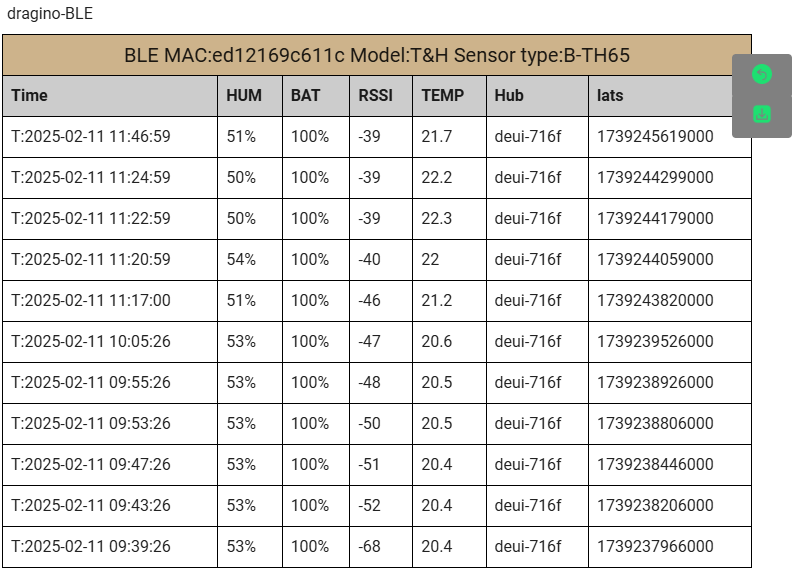
4.1 Dashboard Interface ExampleDashboard Interface Example
The dashboard provides an intuitive interface for real-time monitoring, data analysis, and control.
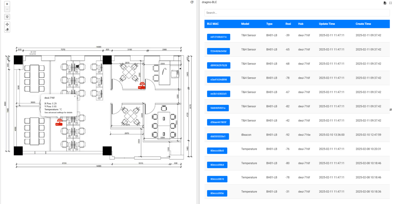
4.2 Detailed Features
- Real-Time Location Tracking As you hover over the entries in the right-hand list, the BH01 icon nearest to the corresponding beacon will highlight in green and display the beacon's name for easy identification.
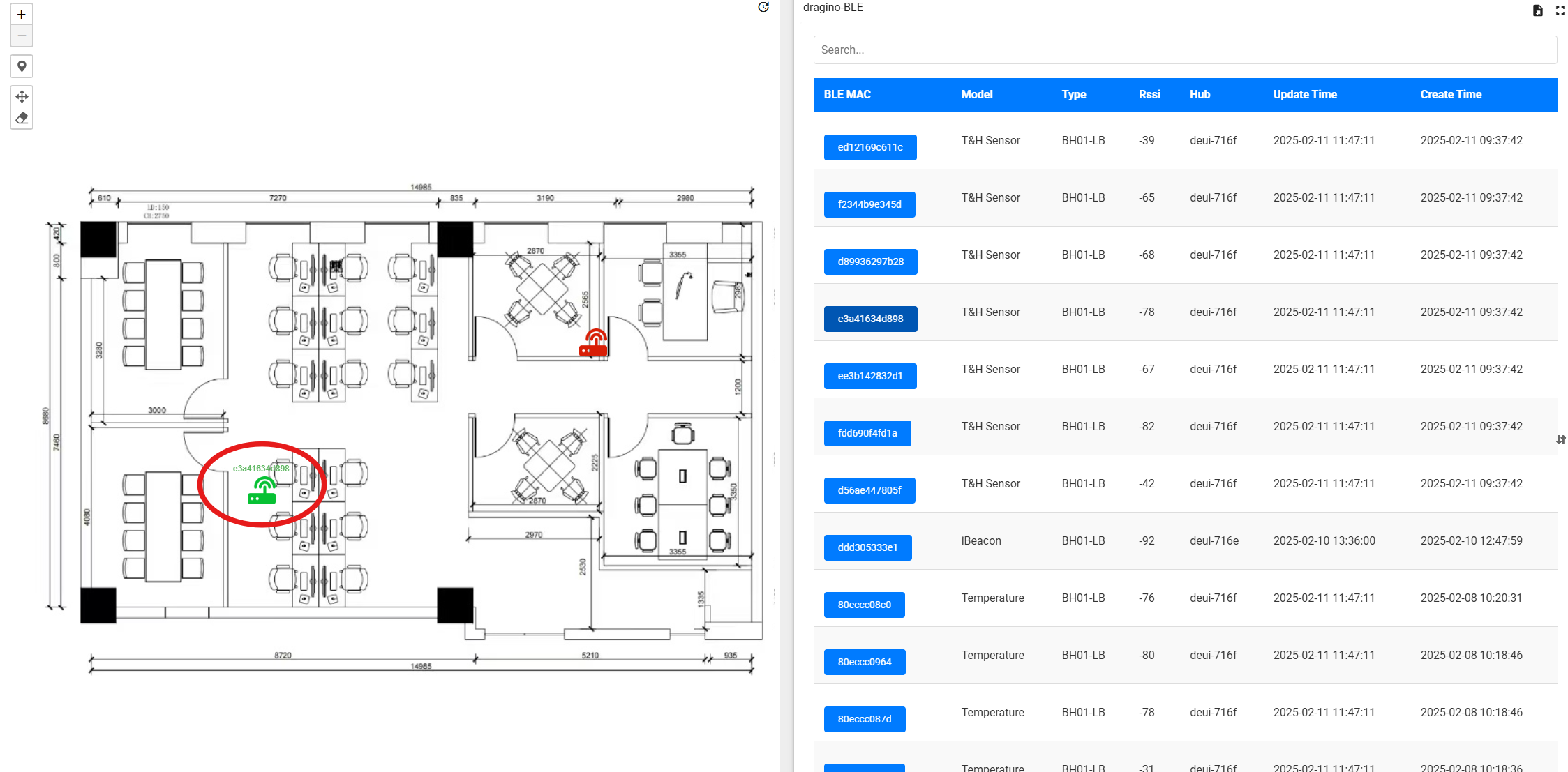
- Beacon Information Access Simply click on any listed beacon name to instantly access detailed information about that specific beacon.
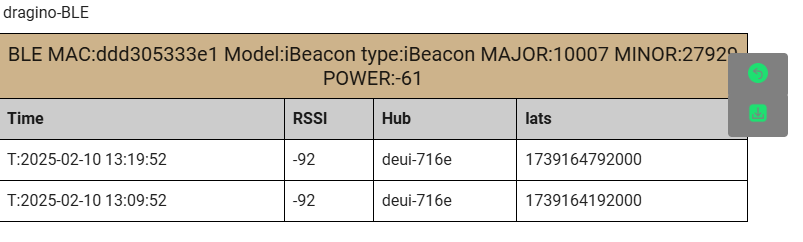
- Temperature & Humidity Monitoring The BH01 devices are equipped with advanced temperature and humidity sensors. You can monitor real-time environmental conditions, with current temperature and humidity readings readily available for your review.
5. Battery & Power Consumption
BH01-LB use ER26500 + SPC1520 battery pack and BH01-LS use 3000mAh Recharable Battery with Solar Panel. See below link for detail information about the battery info and how to replace.
Battery Info & Power Consumption Analyze .
6.FAQ
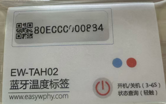
6.1 DR-TAH02 Configuration Method
1. Download the configuration tool
EW_smartconfig (Android Click to download )
2. Select a searchable device
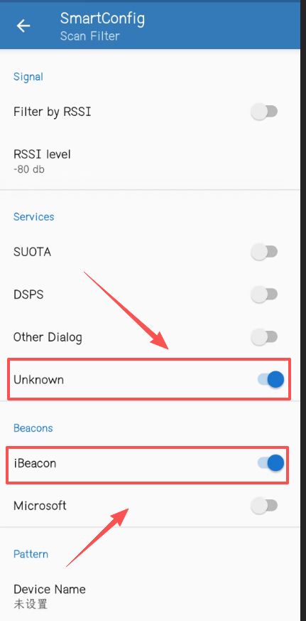
3. Connect to the device
Name prefix: TAH Name suffix: The same as the MAC address on the label
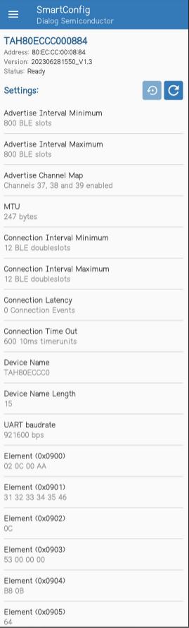
4. Configure various parameters
- All parameters and corresponding addresses of the beacon
TAH02 Temperature Label Specification
The following is the parameter configuration description of the temperature label, the project needs to be configured by the app, you can refer to the following list and related process description.
| command code | length | Default | function |
|---|---|---|---|
| 0x0100 | 2 | 800 | Minimum broadcast interval |
| 0x0101 | 2 | 800 | Broadcast interval maximum |
| 0x0102 | 1 | 7 | Broadcast channel |
| 0x0201 | 2 | 247 | MTU settings |
| 0x0300 | 2 | 12 | Minimum connection interval |
| 0x0301 | 2 | 12 | Maximum connection interval |
| 0x0302 | 2 | 0 | Connection Delay Settings |
| 0x0303 | 2 | 600 | Connection timeout setting |
| 0x0404 | 32 | EW+MAC address | Device name |
| 0x0405 | 1 | 14 | Device Name Length |
| 0x0900 | 4 | 000000AA | state |
| 0x0901 | 6 | 31 32 33 34 35 46 | Login password |
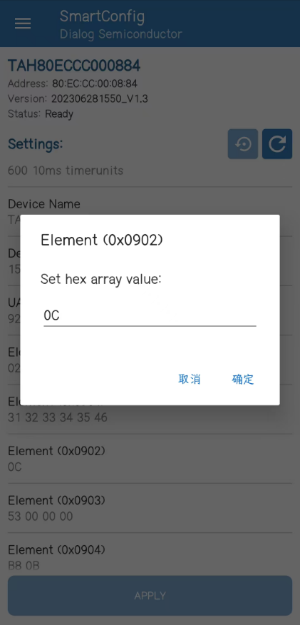
| 0x0902 | 1 | 0C | Transmit power |
| 0x0903 | 4 | 53000000 | Set up |
| 0x0904 | 2 | B80B | Login timeout |
| 0x0905 | 1 | 64 | Battery level |
| 0x0906 | 2 | 500 (unit 10ms) | Battery sampling cycle |
| 0x0907 | 2 | 0701 (26.3 degrees) | Current temperature |
| 0x0908 | 4 | 3075 | Temperature sampling cycle |
| 0x0909 | 4 | 0 | Number of historical records |
| 0x090A | 1 | 01 | command |
| 0x090B | 2 | 0 | History command |
Transmitting power
This command is to set the transmit power of the temperature label, you can set 12 levels of gears, you can choose the appropriate power level according to the actual use needs, the smaller the power, the closer the distance, the greater the power, the farther the distance, the specific actual distance, need to be tested according to the actual situation. The default transmit power is 2.5dBm, and the setting value is 0x0c.
| Take the value | Corresponding transmit power | distance |
|---|---|---|
| 0x01 | -19.5dBm | / |
| 0x02 | -13.5dBm | / |
| 0x03 | -10dBm | / |
| 0x04 | -7dBm | / |
| 0x05 | -5dBm | / |
| 0x06 | -3.5dBm | / |
| 0x07 | -2dBm | / |
| 0x08 | -1dBm | / |
| 0x09 | 0dBm | / |
| 0x0A | 1dBm | / |
| 0x0B | 1.5dBm | / |
| 0x0C | 2.5dBm (default) | 100 meters |
6.2 DR-ES01 Configuration Method
1. Download the nRF Connect app. Android phones can download it from the Google Play Store. iOS phones can download it from the App Store.
Equipment product specifications
2. Match the device by MAC address and tap Connect.
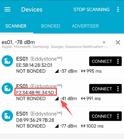
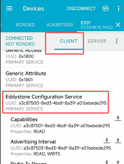
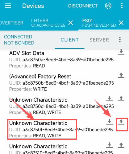
2. You need to find the parameter with 750F in the UUID. Click the up arrow.
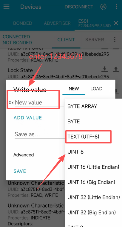
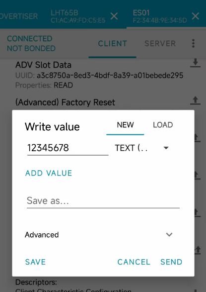
3. Select the correct input data type and enter the correct password 12345678 (this process only takes 30 seconds, please operate quickly otherwise the device will be disconnected)
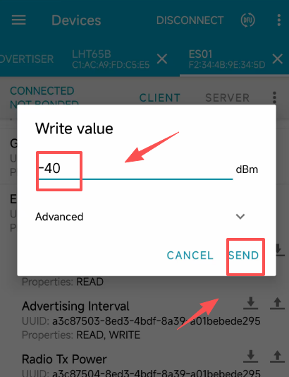
4. Find the parameter name of Radio TX Power and click the up arrow
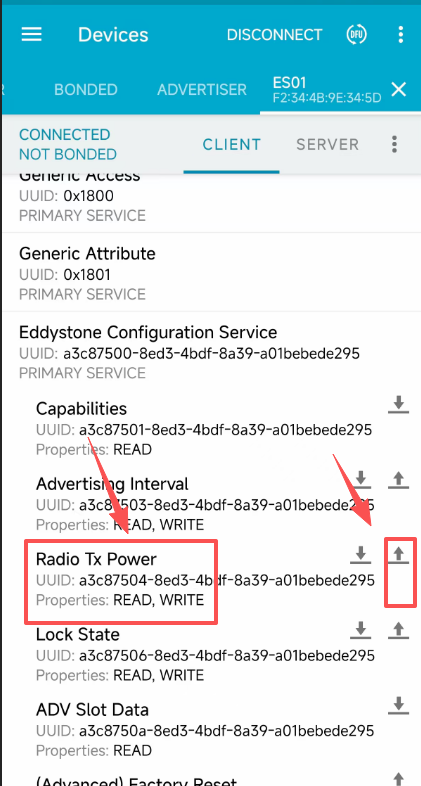
5. Enter the parameters that need to be modified. Please refer to the table below for optional parameters.(Just enter the number, no need to enter dBm)
1 byte, signed, values: -40dbm, -20dbm, -16dbm, -12dbm, -8dbm, -4dbm, 0dbm, 3dbm, 4dbm
6. If you need to modify parameters of other specifications, please refer to the table below
Service UUID description
Service UUID:A3C875008ED34BDF8A39A01BEBEDE295
Feature UUID:
| numbering | function | Characteristic UUID | Function Description (LSB Method) |
|---|---|---|---|
| 1 | attribute | A3C875018ED34BDF8A39A01BEBEDE295 | 15 bytes |
| 2 | Broadcast intervals | A3C875038ED34BDF8A39A01BEBEDE295 | 2 bytes, MSB, value range: 500ms-10240ms |
| 3 | Transmit power | A3C875048ED34BDF8A39A01BEBEDE295 | 1 byte, signed, values: -40dbm, -20dbm, -16dbm, -12dbm, -8dbm, -4dbm, 0dbm, 3dbm, 4dbm |
| 4 | Locked state | A3C875068ED34BDF8A39A01BEBEDE295 | 1 byte, 0 is unlocked, 1 is locked |
| 5 | Broadcast page raw data settings | A3C8750A8ED34BDF8A39A01BEBEDE295 | \ |
| 6 | Factory reset | A3C8750B8ED34BDF8A39A01BEBEDE295 | 1 byte, with a value of 0X0B to indicate a factory reset |
| 7 | Name setting | A3C8750D8ED34BDF8A39A01BEBEDE295 | 1-20 bytes, default as: ES03 |
| 8 | Password setting | A3C8750F8ED34BDF8A39A01BEBEDE295 | 8 bytes, default: 3132333435363738 (character "12345678") |
| 9 | disposition | A3C875108ED34BDF8A39A01BEBEDE295 | 4 bytes, default: 00000000 |
| 10 | History upload | A3C875118ED34BDF8A39A01BEBEDE295 | 10 bytes, 7 bytes timestamp + 2 bytes temperature value + 1 byte humidity value |
| 11 | Number of historical records | A3C875128ED34BDF8A39A01BEBEDE295 | 8 bytes, number of historical records [0-3], total number of records [4-7] |
| 12 | Temperature and humidity sampling cycle | A3C875138ED34BDF8A39A01BEBEDE295 | Temperature and humidity sampling period, unit ms |
| 13 | Time synchronization | A3C875148ED34BDF8A39A01BEBEDE295 | 7 bytes, time synchronized, 7 byte timestamps |
| 14 | History command | A3C875158ED34BDF8A39A01BEBEDE295 | 1 byte, command, 0: upload history, 1: stop uploading history, 2: clear history |
6.3 Why is there no LED response when I press the button on the solar panel model?
If the LED does not light up when you press the button, it may be because the battery has entered protection mode.
Solution: To reactivate the battery, simply expose the solar panel to direct sunlight. For more details, please refer to: Battery Protection State (Apply to Solar Panel + Li-ion battery)
7. OTA Firmware update
User can change firmware BH01-NB/NS to:
- Change Frequency band/ region.
- Update with new features.
- Fix bugs.
Firmware and changelog can be downloaded from : Firmware download link
Methods to Update Firmware:
- (Recommended way) OTA firmware update via wireless: /docs/wiki/Configuration/end-node/lorawan-ota-firmware/
- Update through UART TTL interface: Instruction.
8. Order Info
Part Number: BH01-NB-XX or BH01-NS-XX
XX: The default frequency band
- AS923: LoRaWAN AS923 band
- AU915: LoRaWAN AU915 band
- EU433: LoRaWAN EU433 band
- EU868: LoRaWAN EU868 band
- KR920: LoRaWAN KR920 band
- US915: LoRaWAN US915 band
- IN865: LoRaWAN IN865 band
- CN470: LoRaWAN CN470 band
Note: Model BH01-NB/NS doesn't include Bluetooth Tags. Bluetooth Tags are purchased seperately.
Bluetooth Tags Option: DR-TAH02 , DR-ES01
9. Packing Info
Package Includes:
- BH01-NB/NS Bluetooth to LoRaWAN Hub
Dimension and weight:
- Device Size: cm
- Device Weight: g
- Package Size / pcs : cm
- Weight / pcs : g
9. Support
-
Support is provided Monday to Friday, from 09:00 to 18:00 GMT+8. Due to different timezones we cannot offer live support. However, your questions will be answered as soon as possible in the before-mentioned schedule.
-
Provide as much information as possible regarding your enquiry (product models, accurately describe your problem and steps to replicate it etc) and send a mail to support@dragino.cc
0