DLOS8N - LoRaWAN IoT Gateway User Manual
DLOS8N - LoRaWAN IoT Gateway User Manual
1. Introduction
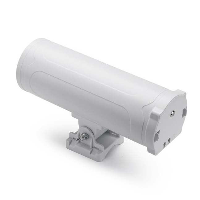
1.1 What is the DLOS8N
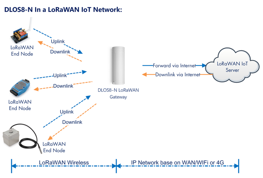
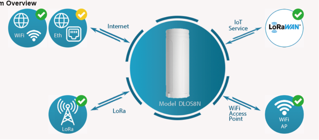
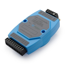
The DLOS8N is an open source outdoor LoRaWAN IoT Gateway. It lets you bridge LoRa wireless network to an IP network via WiFi, Ethernet, 3G or 4G cellular. The LoRa wireless allows users to send data and reach extremely long ranges at low data-rates.
DLOS8N supports Semtech packet forwarder and LoRaWAN Station connection, it is fully compatible with LoRaWAN protocol. DLOS8N includes a SX1302 LoRaWAN concentrator.
DLOS8N has pre-configured standard LoRaWAN frequency bands to use for different countries.User can also customize the frequency bands to use in their own LoRaWAN network.
DLOS8N can communicate with ABP LoRaWAN end node without LoRaWAN server. System integrator can use it to integrate with their existing IoT Service without set up own LoRaWAN server or use 3rd party LoRaWAN service.
DLOS8N supports auto-provision for mass deployment and long term maintain. System intergrator can easily change the settings.
1.2 Specifications
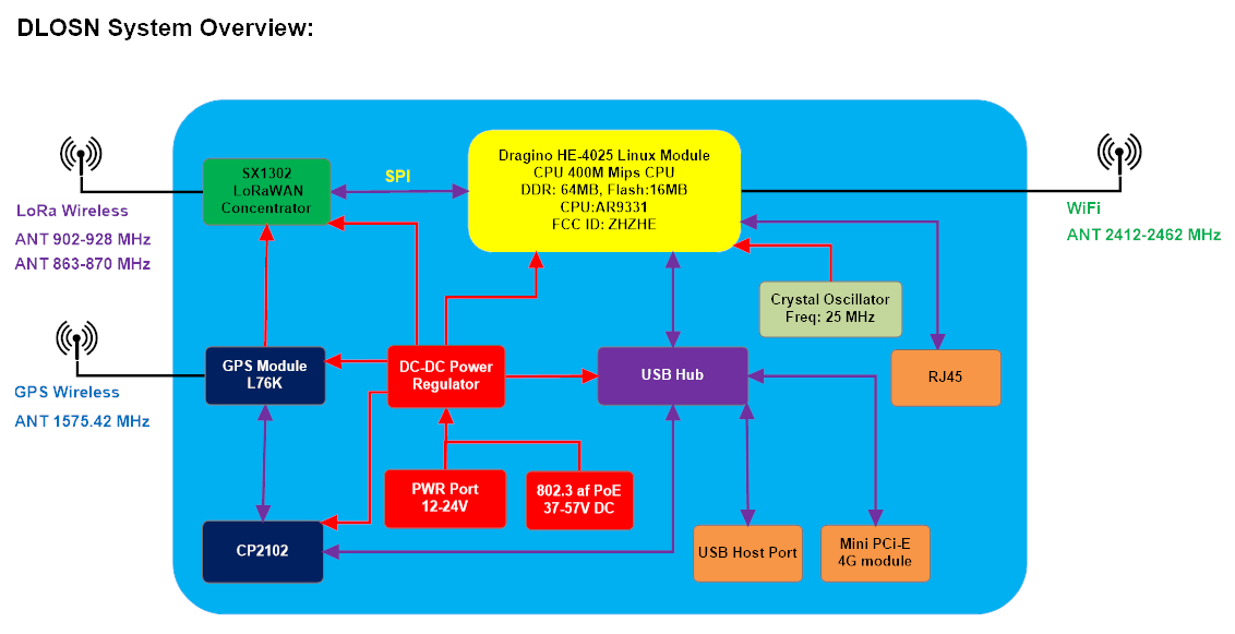
Hardware System: Linux Part:
- 400Mhz ar9331 processor
- 64MB RAM
- 16MB Flash
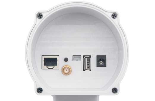
Interface:
- 10M/100M RJ45 Ports x 1
- WiFi : 802.11 b/g/n
- LoRaWAN Wireless
- Power Input: 12 ~ 24 V DC, 2 A
- IEEE 802.3 af compliant PoE port (DC 37 ~ 57 v)
- USB 2.0 host connector x 1
- Mini-PCI E connector x 1
- SX1302 + 2 x SX1250
WiFi Spec:
- IEEE 802.11 b/g/n
- Frequency Band: 2.4 ~ 2.462GHz
- Tx power:
- 11n tx power : mcs7/15: 11db mcs0 : 17db
- 11b tx power: 18db
- 11g 54M tx power: 12db
- 11g 6M tx power: 18db
- Wifi Sensitivity
- 11g 54M : -71dbm
- 11n 20M : -67dbm
LoRa Spec:
- Up to -140 dBm sensitivity with SX1250 Tx/Rx front-end
- 70 dB CW interferer rejection at 1 MHz offset
- Able to operate with negative SNR, CCR up to 9dB
- 8 x 8 channels LoRa packet detectors,8 x SF5-SF12 LoRa demodulators,8 x SF5-SF10 LoRa demodulators,125/250/500 kHz LoRa demodulator and 1 x (G)FSK demodulator
- Dual digital TX & RX radio front-end interfaces
- 10 programmable parallel demodulation paths
- Dynamic data-rate (DDR) adaptation
- True antenna diversity or simultaneous dual-band operation
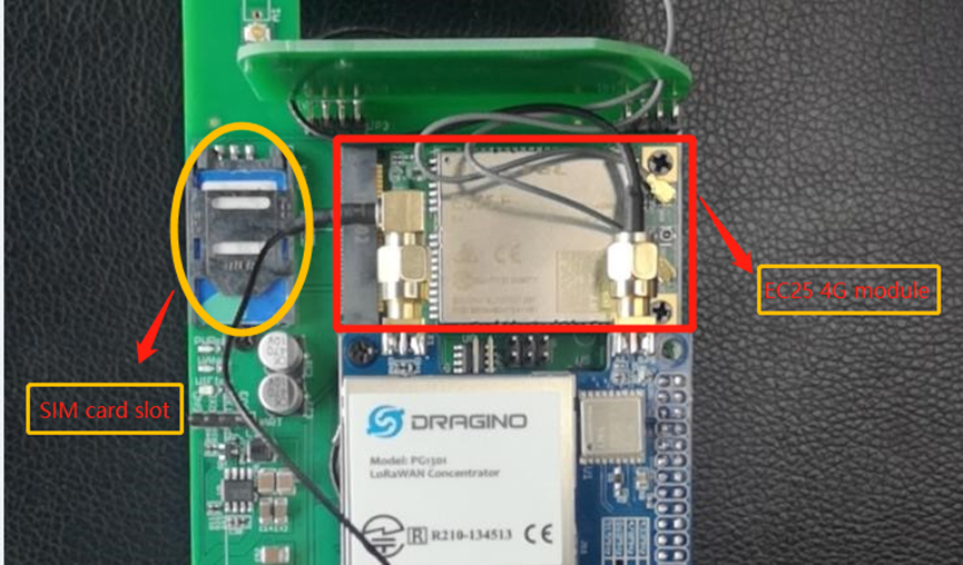
Cellular 4G LTE (optional):
- Quectel: EC25 LTE module
- Standard Size SIM Slot
- 2 x 4G Sticker Antenna.
- Up to 150Mbps downlink and 50Mbps uplink data rates
- Worldwide LTE,UMTS/HSPA+ and GSM/GPRS/EDGE coverage
- MIMO technology meets demands for data rate and link reliability in modem wireless communication systems
Power over Ethernet:
- IEEE 802.3af compliant.
- Support wide input voltage range 37Vdc to 57Vdc.
- Thermal cut off.
- Short circuit protection.
- Over current protection
- Isolation level 4 KVrms.
- Enhanced surge protection
1.3 Features
- Open Source Embedded Linux system
- Managed by Web GUI, SSH via LAN or WiFi
- Support Semtech UDP packet forwarder
- Support LoRaWAN Station Connection
- Support MQTTS
- Cellular Failover conntection(option)
- Direct Communication to LoRaWAN ABP Node
- LoRaWAN packet filtering
- Far seeing LED indicator
- Built-in GPS module for location & timing
- External fiber glass antenna
- Auto-Provision
- Remote Monitoring
- 802.3af PoE
- IP65
- Lightning Protection
- Power Consumption:12v ,300-500mA
- Operating Temperature: -40~85°C
1.4 Hardware System Structure
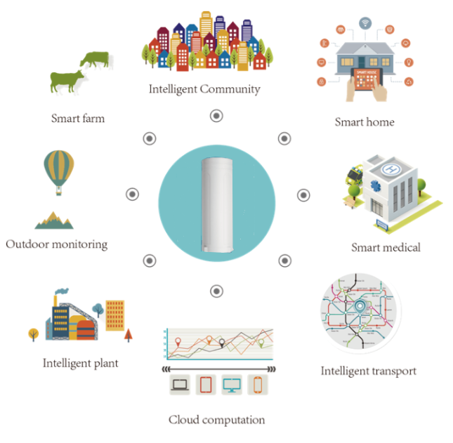
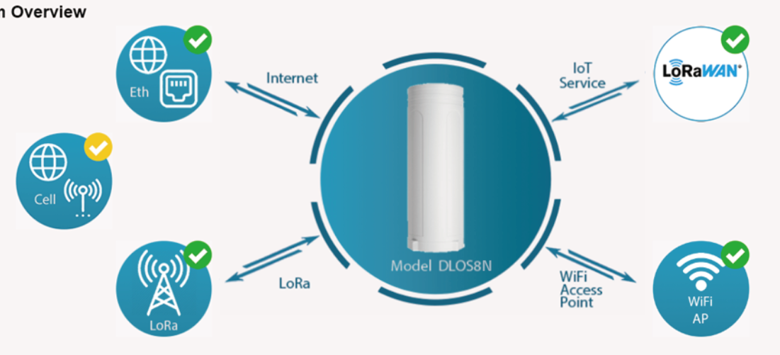
1.5 DLOS8N Applications
1.6 LED Indicators

There is a waterproof triple color LED on DLOS8N enclosure, the meaning of the LED is:
SOLID GREEN: DLOS8N is alive with LoRaWAN server connection.
BLINKING GREEN: a) Device has internet connection but no LoRaWAN Connection. or b) Device is in booting stage, in this stage, it will BLINKING GREEN for several seconds and then RED and YELLOW will blink together.
SOLID RED: Device doesn't have Internet connection.
1.7 Button Instruction
DLOS8N has a black toggle button, which is:
***➢ *Long press 4-5s: **the gateway will reload the Network and Initialize wifi configuration
**LED status: ** LED will BLINKING GREEN Until the reload is finished.
**➢ Long press more than 30s: **the gateway will restart and restore factory settings.
**LED status: ** When the user releases the button, the LED will TURN OFF.
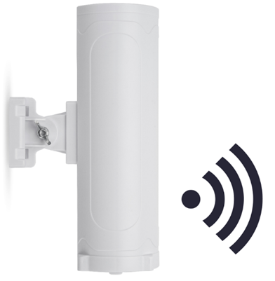
1.8 WiFi Direction
DLOS8N use directional WiFi Antenna. The best direction is as below:
2. Access and Configure DLOS8N
The DLOS8N is configured as a WiFi Access Point by default. User can access and configure the DLOS8N after connecting to its WiFi network, or via its Ethernet port.
2.1 Find IP address of DLOS8N
2.1.1 Connect via WiFi
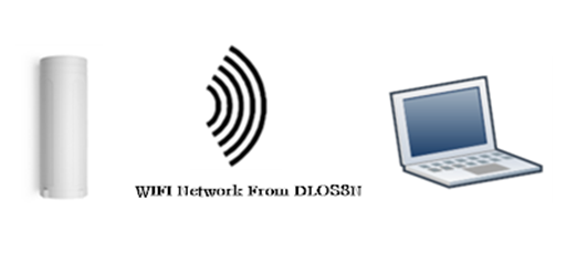
At the first boot of DLOS8N, it will auto generate a WiFi network called ***dragino-xxxxxx ***with password:
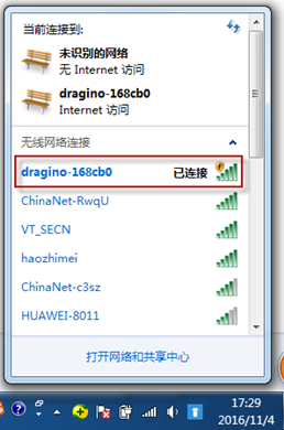
dragino+dragino
User can use a PC to connect to this WiFi network. The PC will get an IP address 10.130.1.xxx and the DLOS8N has the default IP 10.130.1.1
2.1.2 Connect via Ethernet with DHCP IP from router
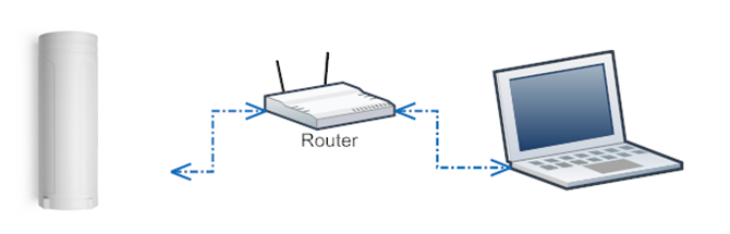
Alternatively, connect the DLOS8N Ethernet port to your router and DLOS8N will obtain an IP address from your router. In the router's management portal, you should be able to find what IP address the router has assigned to the DLOS8N. You can also use this IP to connect.
2.1.3 Connect via WiFi with DHCP IP from router
If the DLOS8N already connect to the router via WiFi, use can use the WiFi IP to connect to DLOS8N.
2.1.4 Connect via Ethernet with fall back ip
The WAN port also has a fall back ip address for access if user doesn't connect to uplink router. Click here to see how to configure.
2.2 Access Configure Web UI
Web Interface
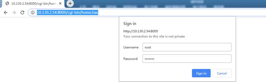
Open a browser on the PC and type the DLOS8N ip address (depends on your connect method)
http://10.130.1.1/ (Access via WiFi AP network)
or
http://IP_ADDRESS or http:// IP_ADDRESS:8000
You will see the login interface of DLOS8N as shown below.
The account details for Web Login are:
User Name: root Password: dragino
3. Typical Network Setup
3.1 Overview
The DLOS8N supports flexible network set up for different environments. This section describes the typical network topology. The network set up includes:
- WAN Port Internet Mode
- WiFi Client Mode
- WiFi AP Mode
- Cellular Mode
3.2 Use WAN port to access Internet
By default, the DLOS8N is set to use the WAN port to connect to an upstream network. When you connect the DLOS8N's WAN port to an upstream router, DLOS8N will get an IP address from the router and have Internet access via the upstream router. The network status can be checked in the home page:
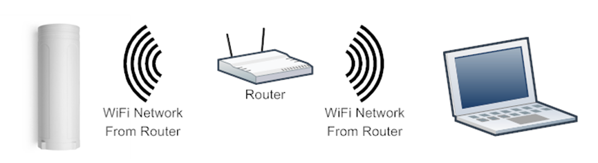
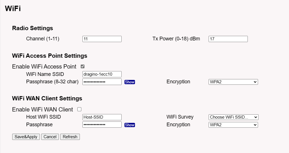
3.3 Access the Internet as a WiFi Client
In the WiFi Client Mode, DLOS8N acts as a WiFi client and gets DHCP from an upstream router via WiFi.
The settings for WiFi Client is under page System--> WiFi --> WiFi WAN Client Settings
In the WiFi Survey Choose the WiFi AP, and input the Passphrase then click Save & Apply to connect.
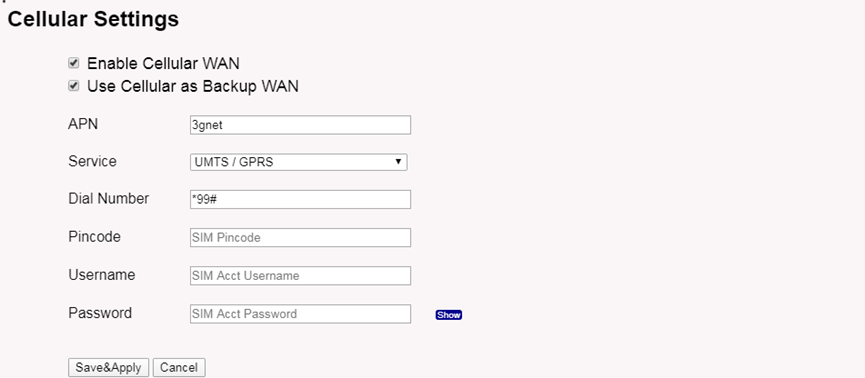
3.4 Access the Internet via Cellular
If the DLOS8N support 3G/4G Cellular modem option, When the label on the shell is displayed as Model : DLOS8N-EC25, it indicates that DLOS8 already has EC25 3G/4G modules,user can use it as main internet connection or back up.
First, release the four screws of DLOS8N, pull out PCB and install SIM card as below:
The set up page is System --> Cellular
While use the cellular as Backup WAN, device will use Cellular for internet connection while WAN port or WiFi is not valid and switch back to WAN port or WiFi after they recover.
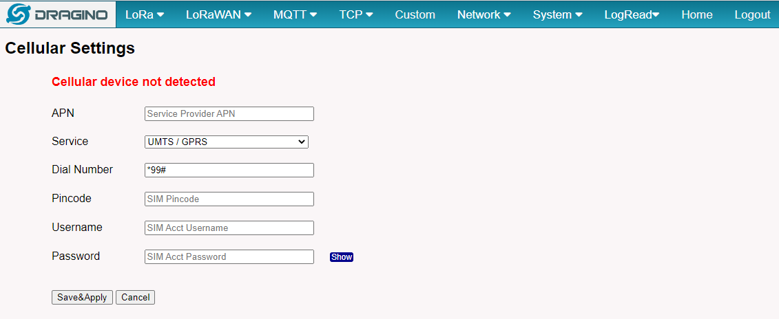
Note *: For DLOS8N which doesn’t have the cellular module, this page will shows Cellular not detected.
When cellular fails to connect or has problems, users can refer to this link to Trouble Shooting:How to Trouble Shooting if Cellular connection fails
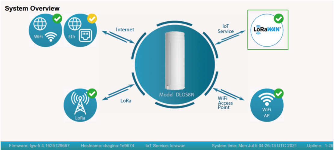
3.5 Check Internet connection
In the home page, we can check the Internet connection.
- GREEN Tick
 : This interface has Internet connection.
 - Yellow Tick
 : This interface has IP address but don't use it for internet connection.
 - RED Cross
 : This interface doesn't connected.
4. Example: Configure as a LoRaWAN gateway
DLOS8N is fully compatible with LoRaWAN protocol. It uses the legacy Semtech Packet forwarder to forward the LoRaWAN packets to server. The structure is as below.
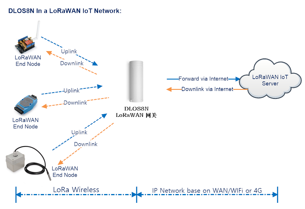
This chapter describes how to use the DLOS8Nto work with
TheThingsNetwork v3(TTN v3) LoRaWAN Server (www.thethingsnetwork.org)
4.1 Create a gateway in TTN V3 Server
Step 1: Get a Unique gateway ID.
Every DLOS8N has a unique gateway id. The ID can be found at LoRaWAN page:
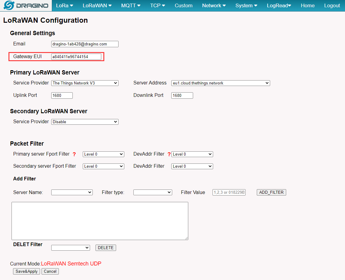
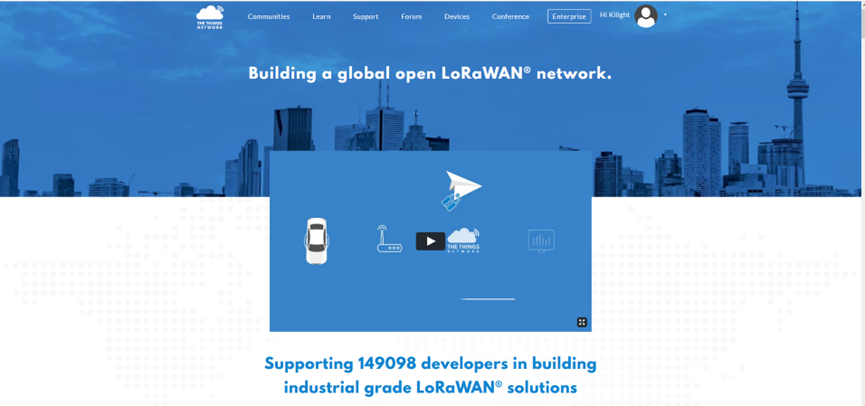
The example gateway id is: a840411e96744154 Step 2: Sign up a user account in TTN server
https://account.thethingsnetwork.org/register
Step 3: Choose the TTNv3 Cluster Picker
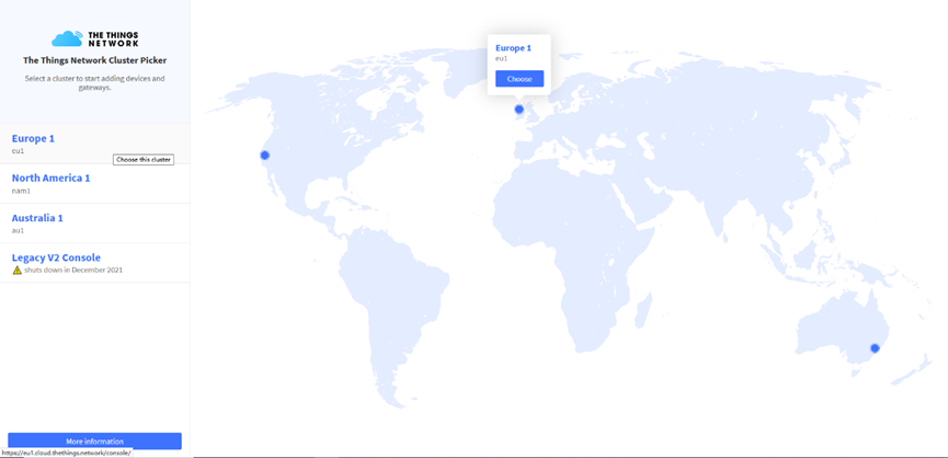
Note: Choose the cluster corresponds to a specific Gateway server address
- Europe 1 corresponding Gateway server address: eu1.cloud.thethings.network
- North America 1 corresponding Gateway server address: nam1.cloud.thethings.network
- Australia 1 corresponding Gateway server address: au1.cloud.thethings.network
- Legacy V2 Console : TTN v2 shuts down in December 2021
Step 4: Create a Gateway
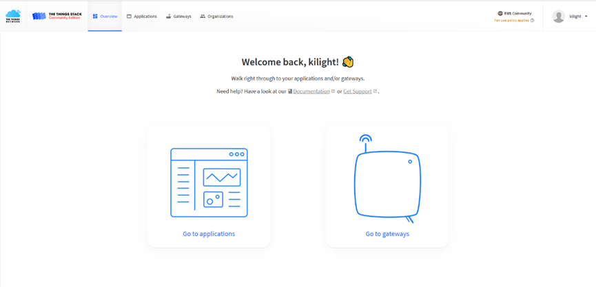
Click the Gateway icon and then click Add gateway.
Open the following page:
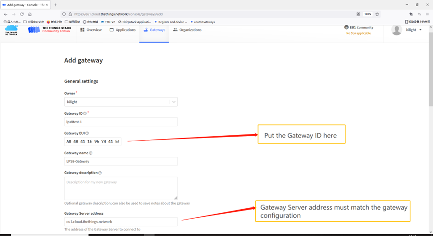
Notice: Gateway Server address must match the gateway configuration, otherwise you will have problem for End Node to join the network.
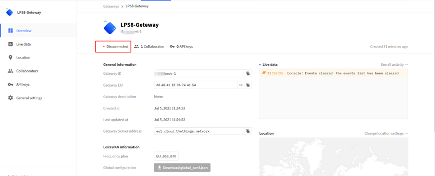
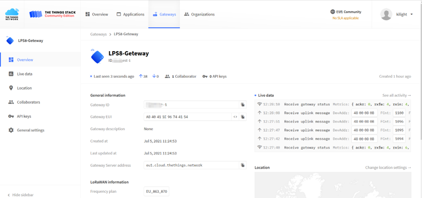
After creating the gateway, you can see the gateway info, as below.
4.2 Configure DLOS8N to connect to TTN v3
You can now configure the DLOS8N to let it connect to TTN network V3.
Make sure your DLOS8N has a working Internet Connection first.
Choose the right server provider and click Save&Apply
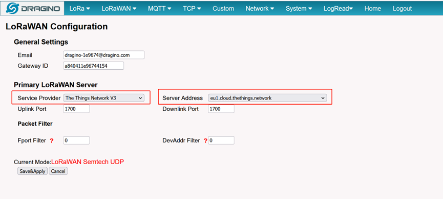
Note: The server address must match the Gateway server address you choose in TTN V3.
In the home page, we can see the LoRaWAN connection is ready now.
In TTN v3 portal, we can also see the gateway is connected.
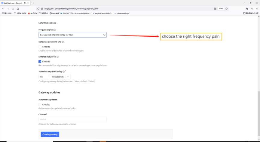
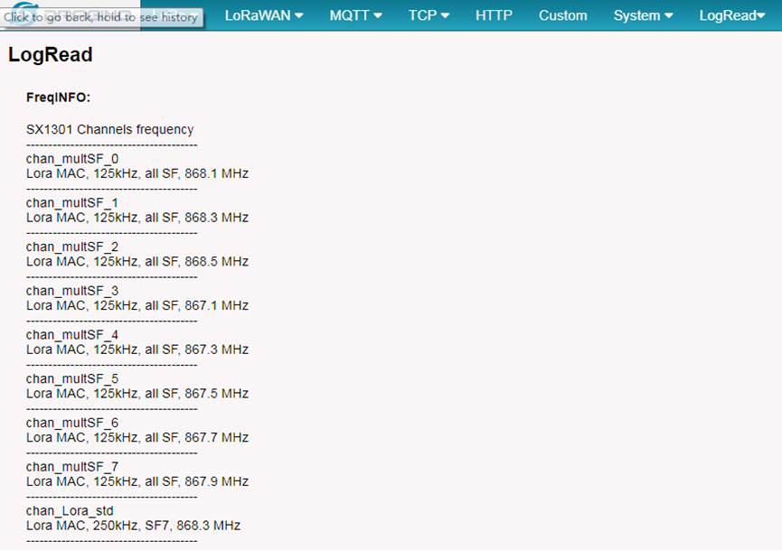
4.3 Configure frequency
We also need to set the frequency plan in DLOS8N to match the end node we use, so to receive the LoRaWAN packets from the LoRaWAN sensor.
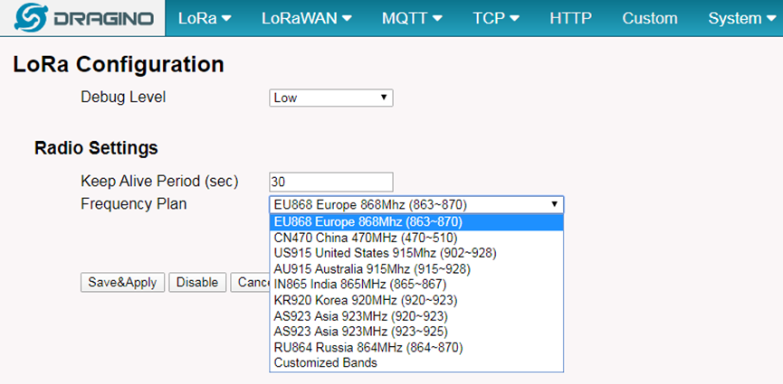
In logread page, user can check the frequency actually used.
4.4 Add a LoRaWAN End Device
This section shows how to add a LoRaWAN End device to a LoRaWAN network and see the data from TTN web site.
We use LT-22222-L IO Controller as a reference device - the setup for other LoRaWAN devices will be similar.
Step 1: Create a Device definition in TTN v3 with the OTAA keys from the example LT-22222-L IO Controller device.
Three codes are required to define the device in TTN v3:
- DEV EUI - Unique ID code for a particular device.
- APP EUI - ID code for an Application defined in TTN v3.
- APP Key - Unique key to secure communications with a particular device.
A set of these codes are stored in each device by the manufacturer as the default codes for that particular device. Each device is shipped with a sticker with the default Device EUI as shown below.
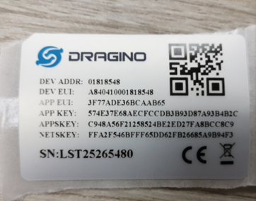
Note: You may be able to change these codes in a device by using a configuration facility on the device e.g. the LT-22222 uses a serial port access and a series of AT commands. Changing the codes may be necessary in the case where you have to use codes assigned by a LoRa WAN server.
For the TTN v3 server, you can use the codes set in the device as in the following example.
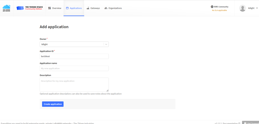
Select Add Application to open the screen below.
Open the Application select Add end device
Start Register the end device
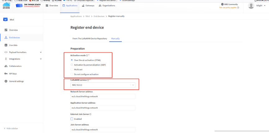
Select OTAA activation mode
The LoRaWAN version for your device should be provided by the manufacturer in a datasheet as LoRaWAN version or LoRaWAN specification. The most commonly used LoRaWAN versions are v1.0.2 and v1.0.3.
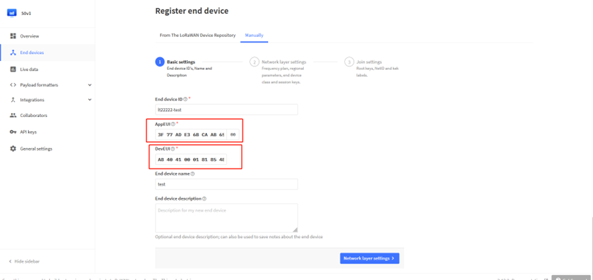
First, input the End device ID, AppEUI and DevEUI.
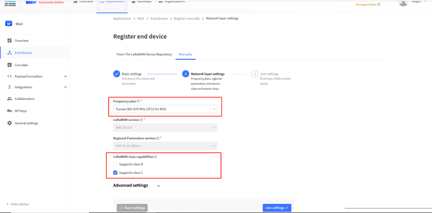
Secondly, choose the corresponding frequency and LoRaWAN class capabilities.
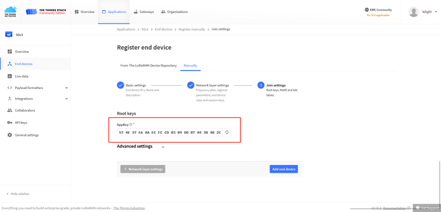
Finally, Application layer settings input the corresponding AppKey. Before saving the configuration, check that the data matches the device.
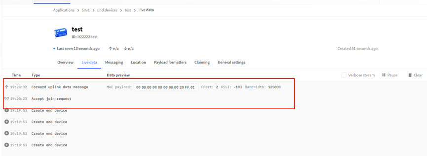
Step 2: Power on LT-22222-L device and it will automatically join the TTN network. After joining successfully, it will start to upload messages to the TTN v3. Select the Live data tab and you will see the data appearing in the panel.
Note that it may take some time for the device data to appear in the TTN v3 display.
5. Web Configure Pages
5.1 Home
Shows the system running status.
5.2 LoRa Settings
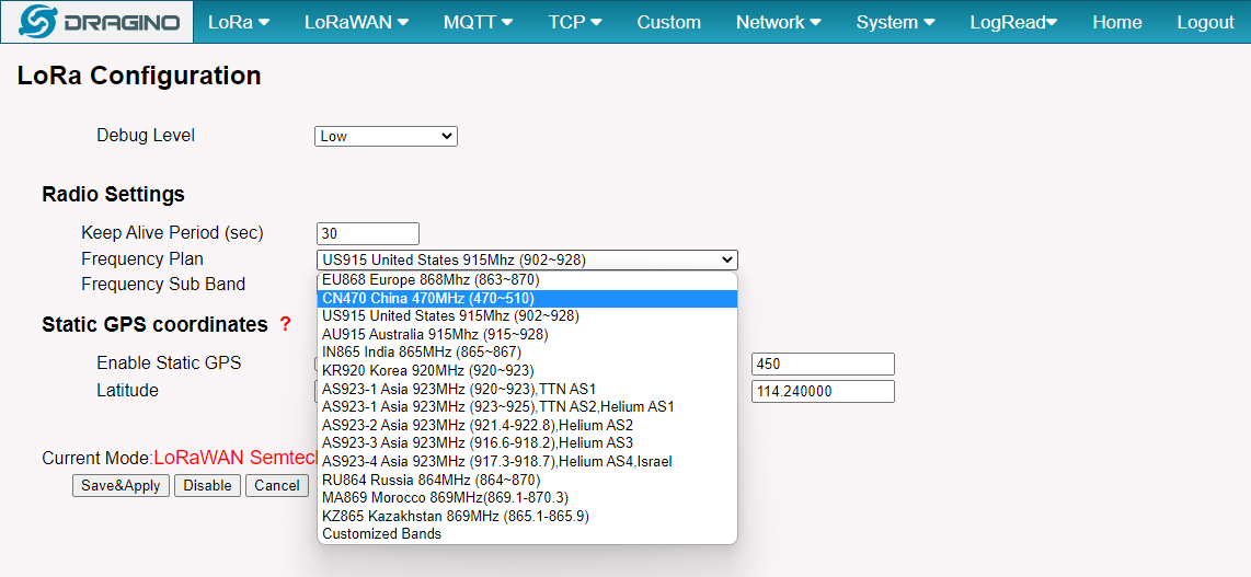
5.2.1 LoRa --> LoRa
This page shows the LoRa Radio Settings. There are a set of default frequency band according to LoRaWAN protocol, and user can customized the band* as well.
Different DLOS8N hardware version can support different frequency range:
- 868: valid frequency: 863Mhz ~ 870Mhz. for bands:
EU868、RU864、IN865、KZ865 - 915: valid frequency: 902Mhz ~ 928Mhz. for bands:
US915、AU915、AS923、KR920
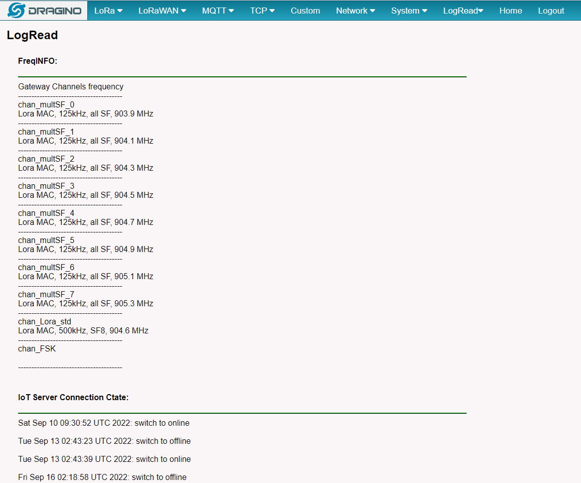
After user choose the frequency plan, he can see the actually frequency in used by checking the page LogRead --> LoRa Log
Note *: See this instruction for how to customize frequency band
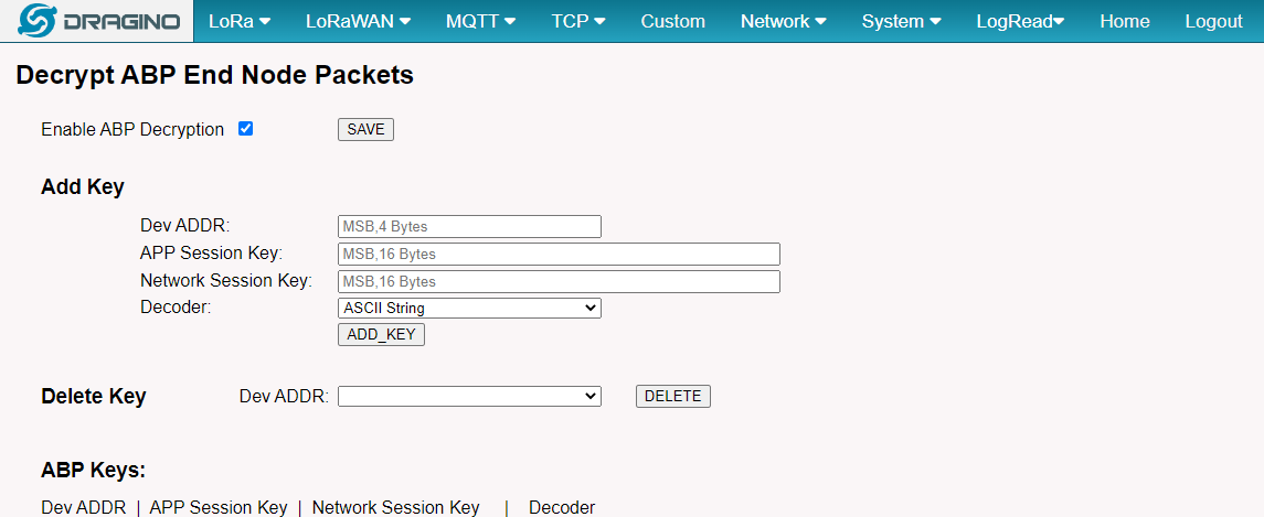
5.2.2 LoRa --> ABP Decryption
The DLOS8N can communicate with LoRaWAN ABP End Node without the need of LoRaWAN server. It can be used in some cases such as:
- No internet connection.
- User wants to get data forward in gateway and forward to their server based on MQTT/HTTP, etc. (Combine ABP communication method and MQTT forward together).
Detail of this feature: Communication with ABP End Node
5.3 LoRaWAN Settings
5.3.1 LoRaWAN --> Semtech UDP
This page is for the connection set up to a general LoRaWAN Network server such as: TTN, ChirpStack etc.
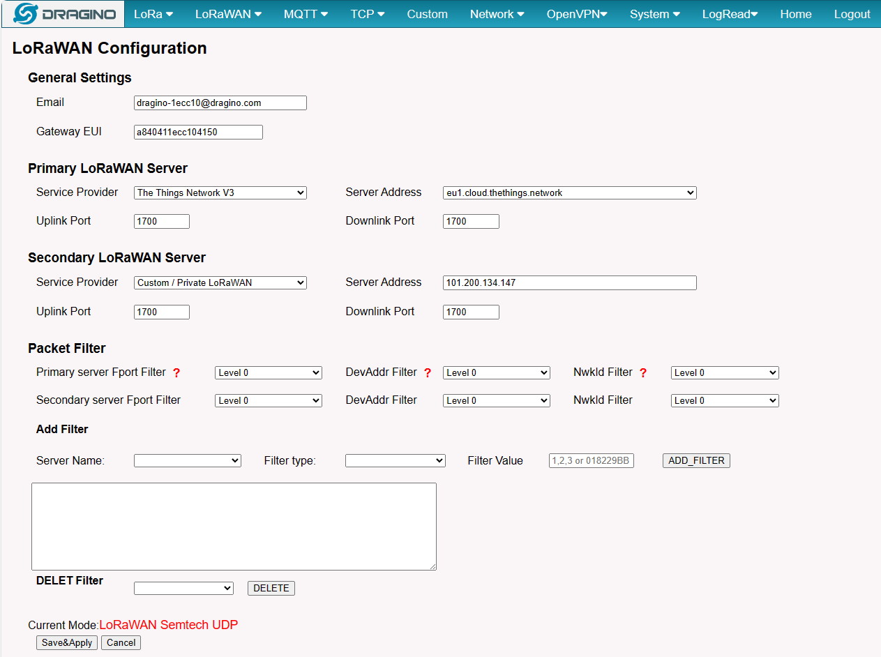
Note:
*: User can ignore the latitude and longitude settings here, DLOS8N will use the actually value from GPS module.
**: Packet filter is to drop the unwanted LoRaWAN packet, instruction see here:
See: Filter unwanted LoRaWAN packets
5.3.2 LoRaWAN --> Basic Station
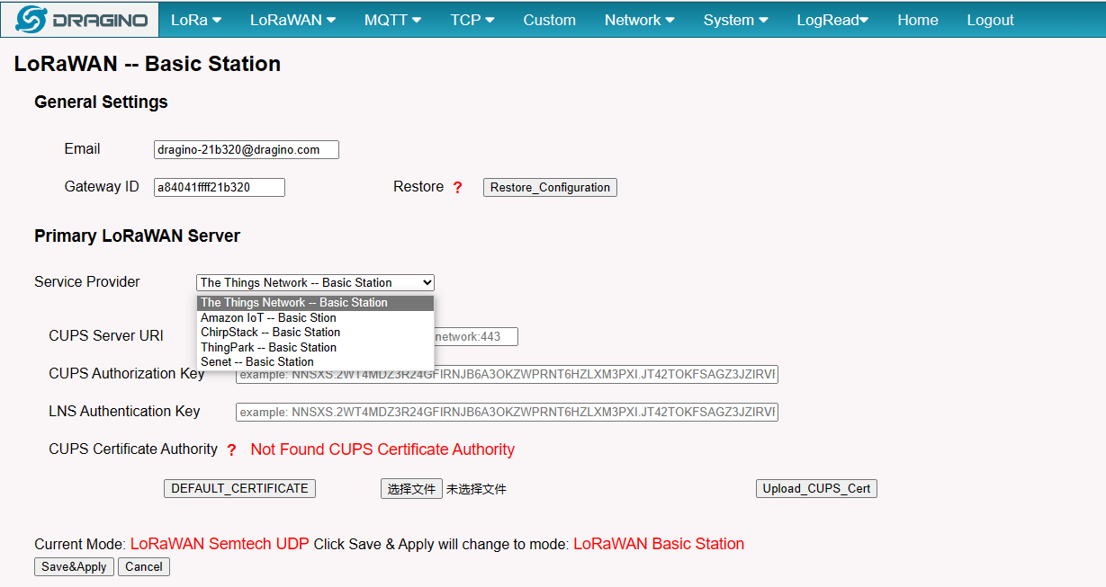
Introduction for the use of LoRaWAN Basic for different servers:
- Introduction to using with AWS-IoT LoRaWAN Core.
- Introduction to using with TTN.
- Introduction to using with ChirpStack.
- Introduction to using with Senet.
- Introduction to using with Actility Thingpark Enterprise.
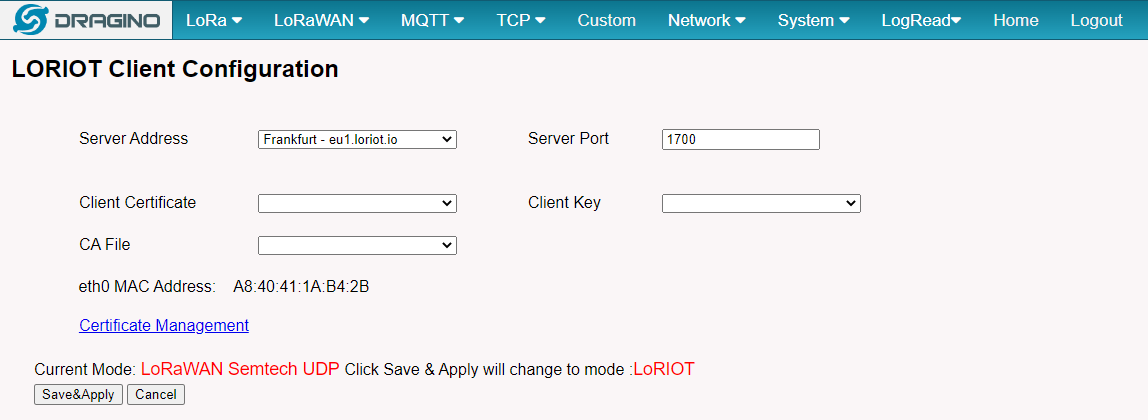
5.3.3 LoRaWAN --> LORIOT
Settings to communicate to LORIOT LoRaWAN Network Server: https://www.loriot.io/
Instruction: Notes for LORIOT
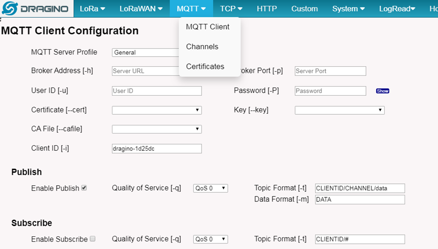
5.4 MQTT Settings
If end nodes works in ABP mode, user can configure DLOS8N to transfer the data to MQTT broker,
Instruction: MQTT Forward Instruction
5.5 Network
5.5.1 Network --> Network Status
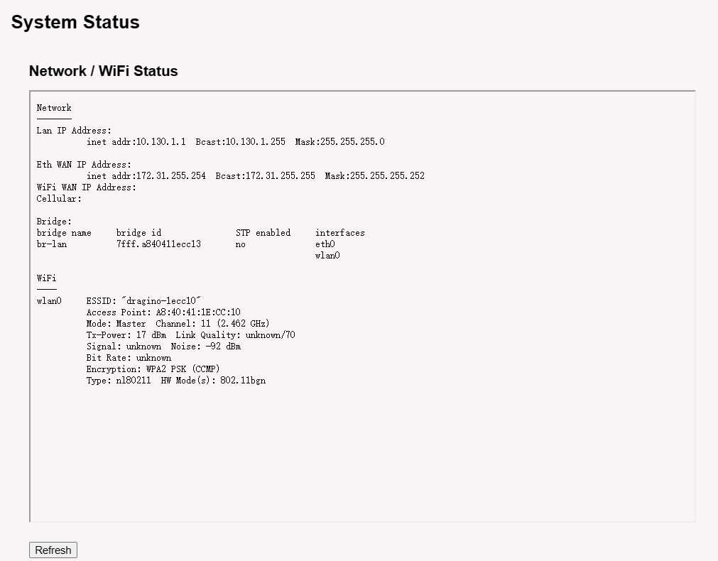
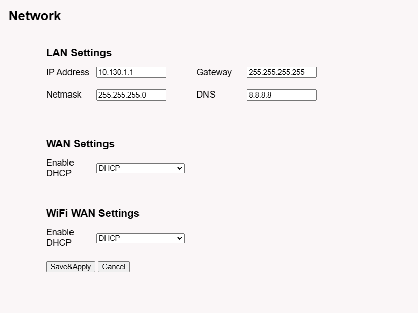
5.5.2 Network --> Network
**LAN Settings: **When the DLOS8N has the AP enable, LAN settings specify the network info for DLOS8N's own network.
**WAN Settings: **Setting for DLOS8N WAN port
**WiFi Settings: Setting for DLOS8N WiFi IP when use it as WiFi Client
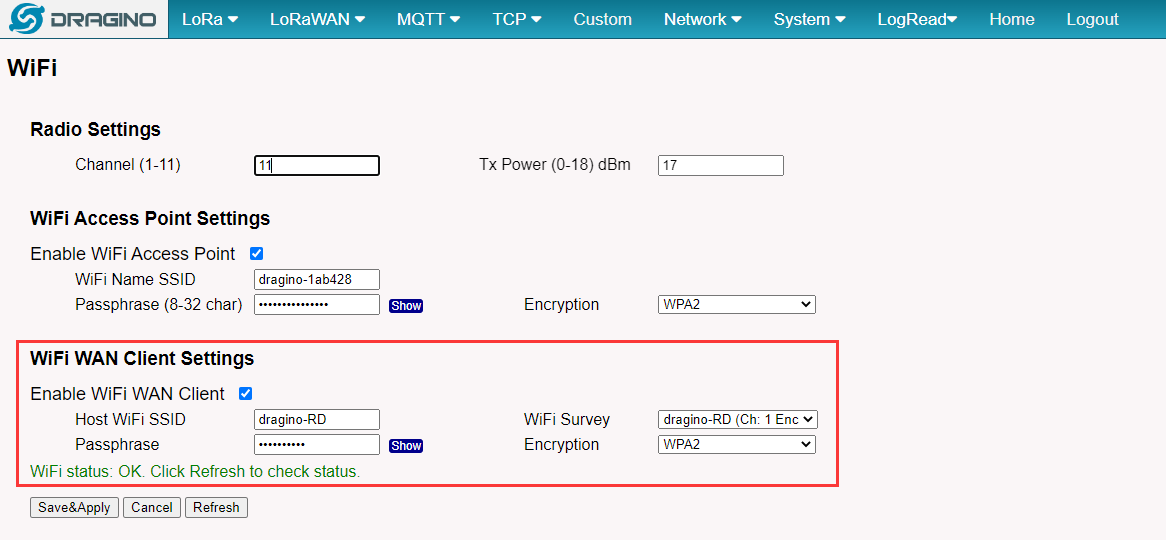
5.5.3 Network --> WiFi
DLOS8N WiFi Settings.
5.5.4 Network --> Cellular
While use the cellular as Backup WAN, device will use Cellular for internet connection while WAN port or WiFi is not valid and switch back to WAN port or WiFi after they recover.
Note *: For DLOS8N which doesn't have the cellular module, this page will shows Cellular not detected.
When cellular fails to connect or has problems, users can refer to this link to Trouble Shooting:How to Trouble Shooting if Cellular connection fails
5.6 System
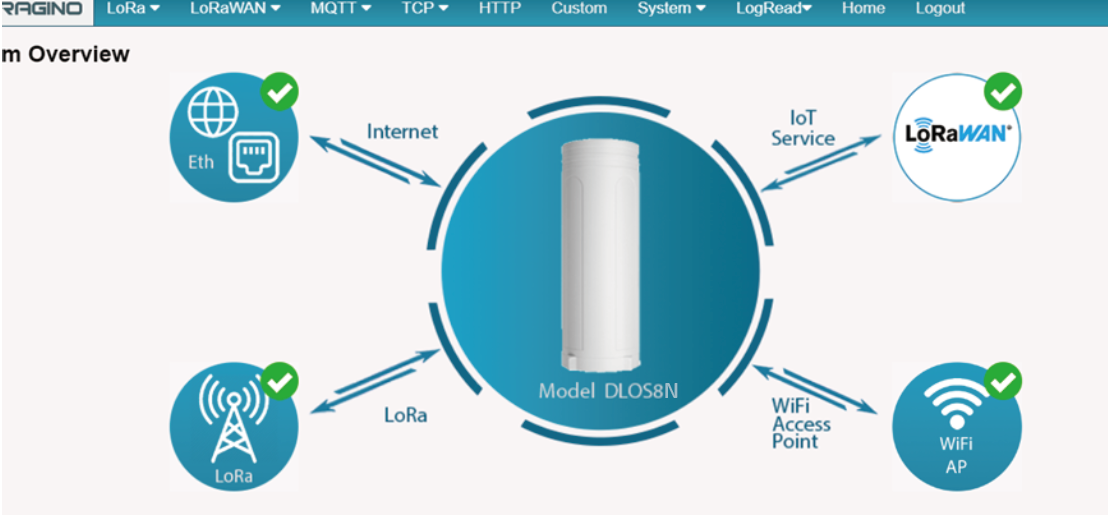
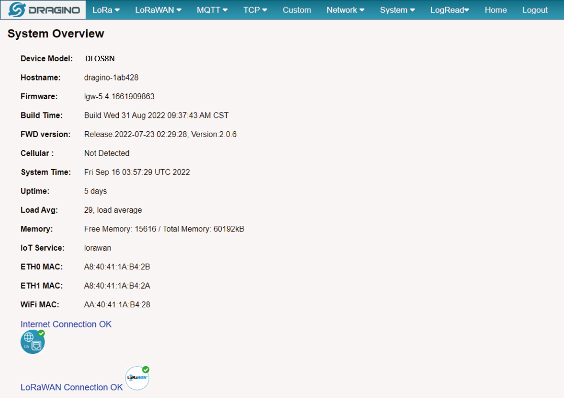
5.6.1 System --> System Overview
Shows the system info:
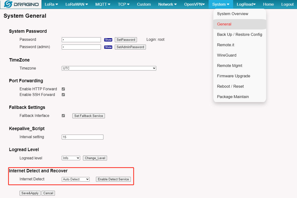
5.6.2 System --> General ( login settings)
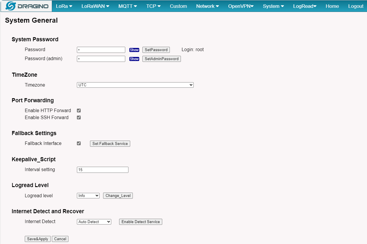
There are two login for DLOS8N: root /dragino or admin /dragino. Both root and admin has the same right for WEB access. But root user has also the right to access via SSH to Linux system. admin only able to access WEB interface.
This page can be used to set the password for them.
**Timezone: **Set device timezone.
**Port forwarding: **Enable/Disable the HTTP and SSH access via WAN interface.
**Fallback Settings: **Enable/Disable the Fallback interface.
**Keepalive_Script: **Set the keepalive_scrpt interval.
**Logread Level: **Change the logread level.
**Internet Detect and Recover: Auto Detect: **Internet Detect is enabled by default. When there is no gateway network, it will reboot after 15 minutes.
**Manual Detect: **In Manual Detect, User can choose wifi, ethernet, 4g or disable detect
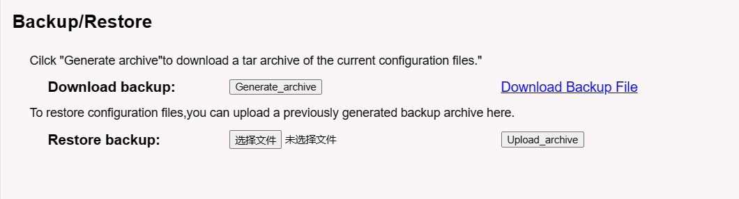
5.6.3 System --> Backup/Restore Config
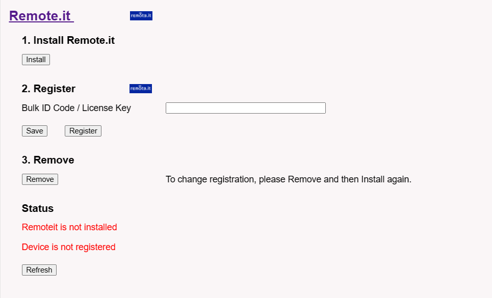
5.6.4 System --> Remote.it
In the System-> Remoteit interface, users can configure the gateway to be accessed remotely via Remote.it.
the users can refer to this link to configure them: Monitor & Remote Access Gateway
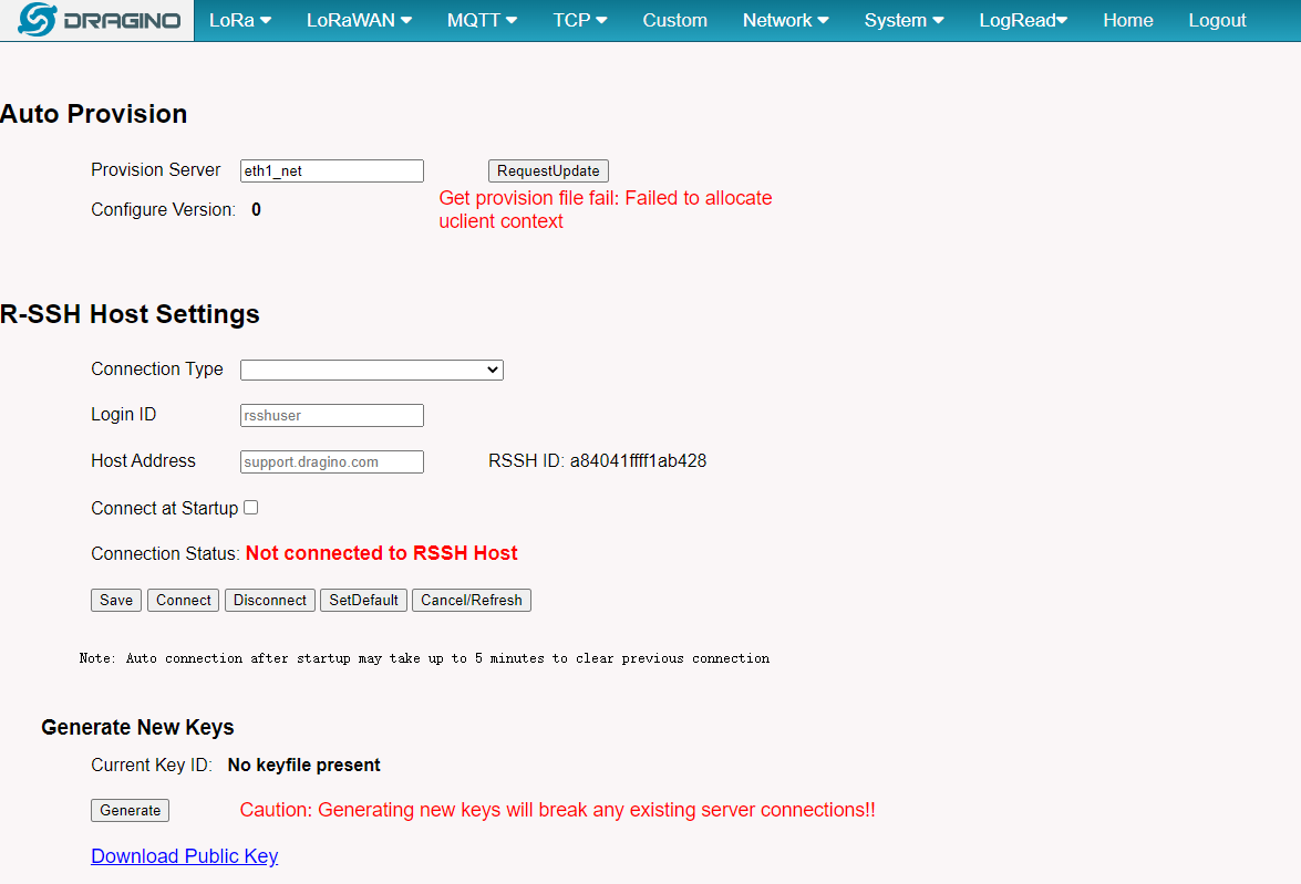
5.6.5 System --> Remote Mgnt & Auto Provision
Auto Provision is the feature for batch configure and remote management. It can be used in below two cases:
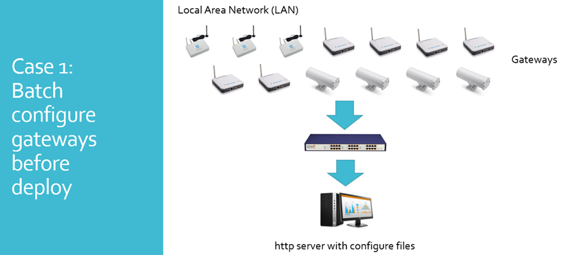
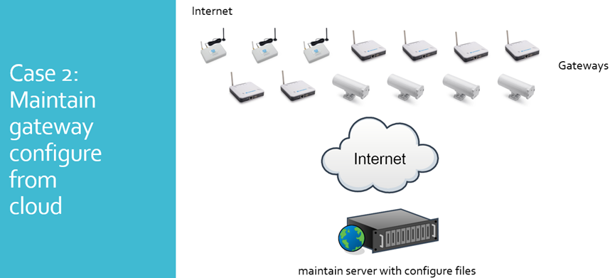
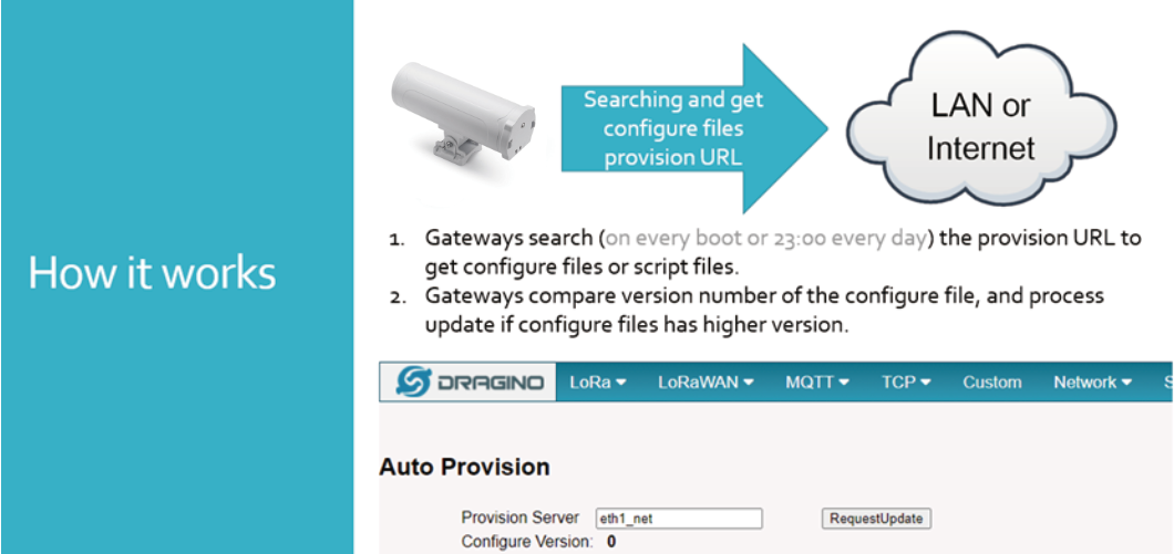
Please see this document for detail:
R-SSH is for remote access device and management, introduction for how to use: Remote Access Gateway
5.6.6 System --> Firmware Upgrade
We keep improving the DLOS8N Linux side firmware for new features and bug fixes. Below are the links for reference.
- Latest firmware: LoRa Gateway Firmware,
( http://www.dragino.com/downloads/index.php?dir=LoRa_Gateway/LG02-OLG02/Firmware )
- Change Log: Firmware Change Log.
( http://www.dragino.com/downloads/downloads/LoRa_Gateway/LG02-OLG02/Firmware/ChangeLog )
The file named as **xxxxx–xxxxx-squashfs-sysupgrade.bin **is the upgrade Image. There are different methods to upgrade, as below.
Web--> System--> Firmware Upgrade
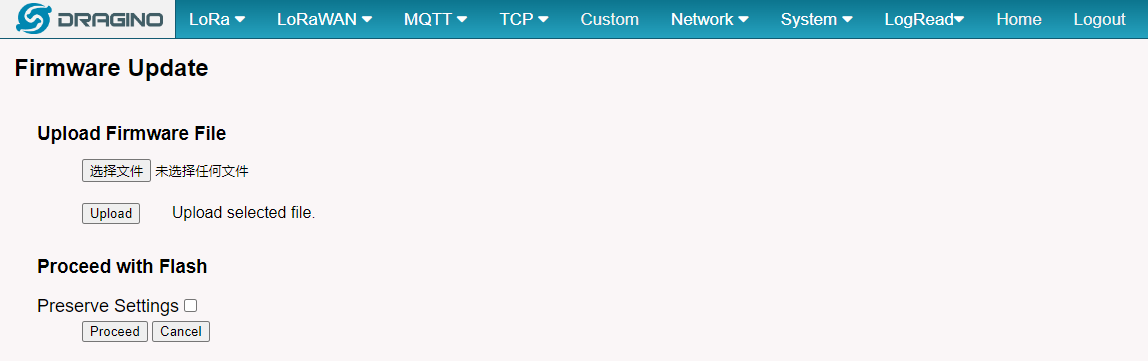
Select the required image and click Flash Image. The image will be uploaded to the device, and then click Process Update to upgrade.
NOTE: You normally need to uncheck the Preserve Settings checkbox when doing an upgrade to ensure that there is no conflict between the old settings and the new firmware. The new firmware will start up with its default settings.
The system will automatically boot into the new firmware after upgrade.

NOTE*: User can also upgrade firmware via Linux console
SCP the firmware to the system**/var **directory and then run
root@OpenWrt:~# /sbin/sysupgrade –n /var/Your_Image NOTE : it is important to transfer the image in the /var directory, otherwise it may exceed the available flash size.
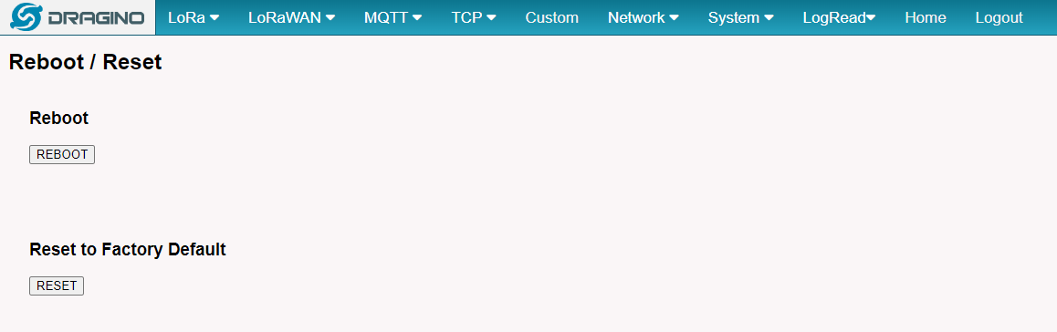
5.6.7 System --> Reboot/Reset
5.6.8 System --> Package Maintain
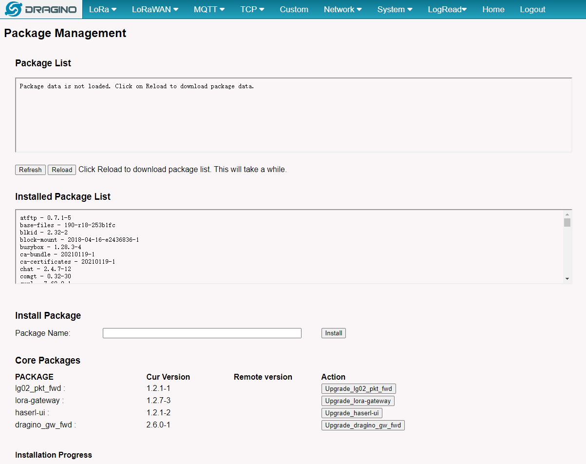
Place to show what package has installed and possible to upgrade packages.
5.7 LogRead
5.7.1 LogRead --> LoRa Log
Show the frequency for LoRa Radio:
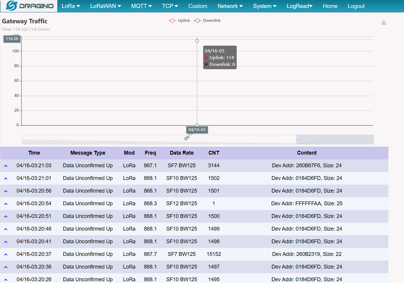
5.7.2 LogRead --> Gateway Traffic
Show the gateway traffic:
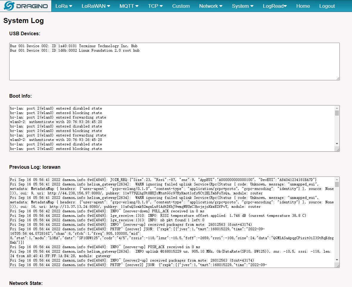
5.7.3 LogRead --> System Log
Show the system log
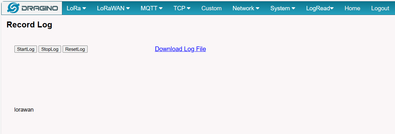
5.7.4 LogRead --> Record Log
This interface can record gateway logs:
6. More features
6.1 NTP Service/Time Synchronization
The gateway time sync service is provided by ntpd
1). Modify the NTP server address:
###Linux command
uci set system.ntp.server='0.openwrt.pool.ntp.org' #Required
uci add_list system.ntp.server='1.openwrt.pool.ntp.org' #Optional
uci add_list system.ntp.server='2.openwrt.pool.ntp.org' #Optional
uci add_list system.ntp.server='3.openwrt.pool.ntp.org' #Optional
uci commit system #Required
**Note: If the NTP server is a Windows host, it may cause the time synchronization to fail, **
6.2 Packet Filtering
Drop unwanted packets.
See: http:///docs/wiki/configuration/gateway/filter-unwanted-lorawan-packets/
6.3 Remote Access
Remote Access Devices for management.
Instruction: http:///docs/wiki/configuration/gateway/monitor-remote-access-gateway/
6.4 How to decode ABP LoRaWAN node
Decode ABP:
http:///docs/wiki/configuration/gateway/communicate-with-abp-end-node-without-lorawan-network-server-lg308/
6.5 How to set data to MQTT broker
Only support ABP LoRaWAN End Node
Instruction: http:///docs/wiki/configuration/gateway/mqtt-forward-instruction/
6.6 How the gateway connects to Chirpstack v3/v4 via gateway-bridge
If the Chirpstack v3 Gateway-bridge is used, the corresponding gateway firmware must be used :
Chirpstack-gateway-bridge/Chirpstack-Bridge-V3.14.6-Bridge--build-v5.4.1679487778-20230322-2024/
Chirpstack v3 via gateway-bridge Instruction: https:///docs/wiki/iot-lorawan-server/network-server/chirpstack/
If the Chirpstack v4 Gateway-bridge is used, the corresponding gateway firmware must be used :
Chirpstack-gateway-bridge/Chirpstack-Bridge-V4--build-v5.4.1670655072-20221210-1452/
Chirpstack v4 via gateway-bridge Instruction: https:///docs/wiki/iot-lorawan-server/network-server/chirpstack/
NOTE*: Different chirpstack versions use different gateway-bridge configurations.
After updating the Chirpstack gateway-bridge firmware, there is no need to re-download and install the Chirpstack gateway-bridge package
6.7 How does the gateway connect to Chirpstack via MQTT Forwarder
ChirpStack MQTT Forwarder is a MQTT packet forwarder for LoRa gateways. By default it forwards packets in Protobuf binary format, optionally it can be configured to use JSON encoding for debugging. In contrast to the ChirpStack Gateway Bridge, this component must always be installed on the gateway.
6.7.1 Configure Packet Forwarder
In the Dragino web-interface, you must configure the Packet Forwarder such that it forwards to localhost on port 1700.
By default, the web-interface can be accessed by entering the following URL in your browser: https://GATEWAY-IP-ADDRESS:8000 (replace GATEWAY-IP-ADDRESS by the actual IP address of your gateway). The default credentials are root / dragino.
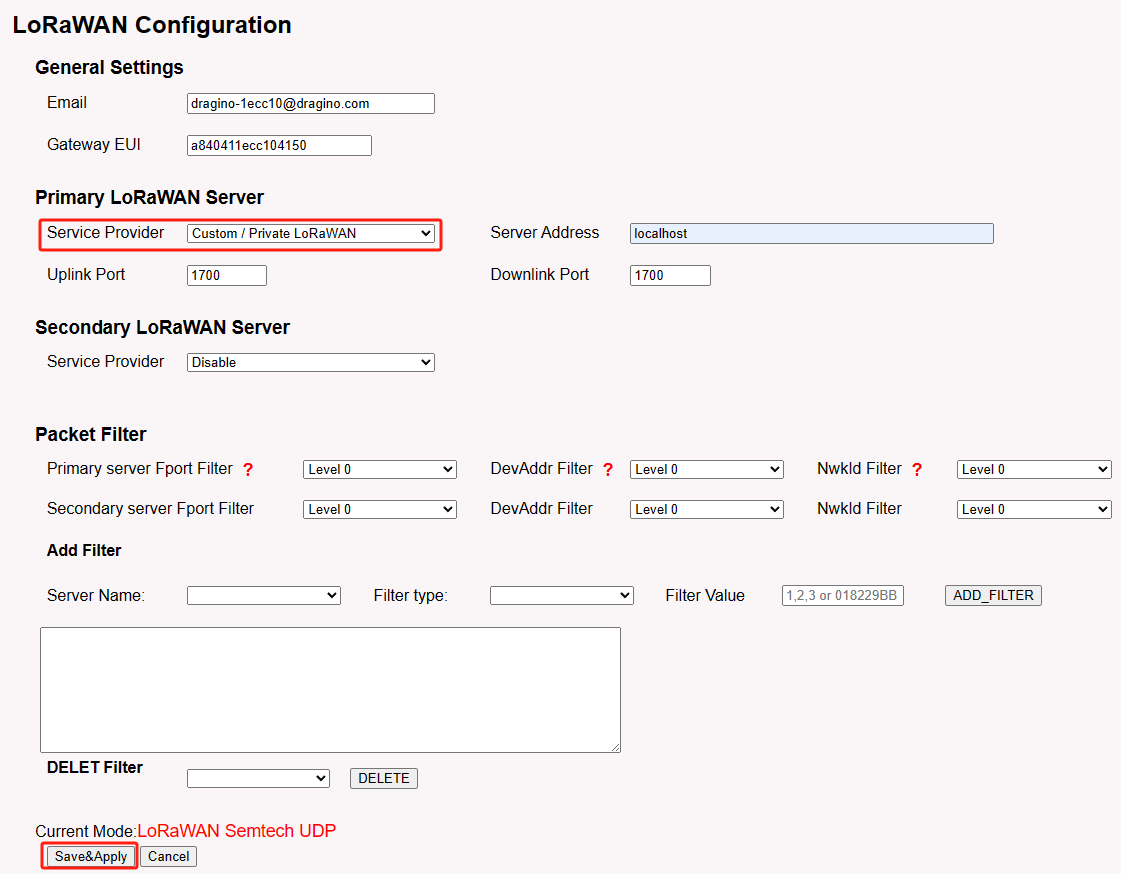
- In the LoRaWAN menu, click LoRaWAN -- Semtech UDP
- Configure the following settings:
- Service Provider: Custom / Private LoRaWAN
- Server Address: localhost
- Uplink Port: 1700
- Downlink Port: 1700
- Click Save&Apply
6.7.2 Install ChirpStack MQTT Forwarder
SSH login
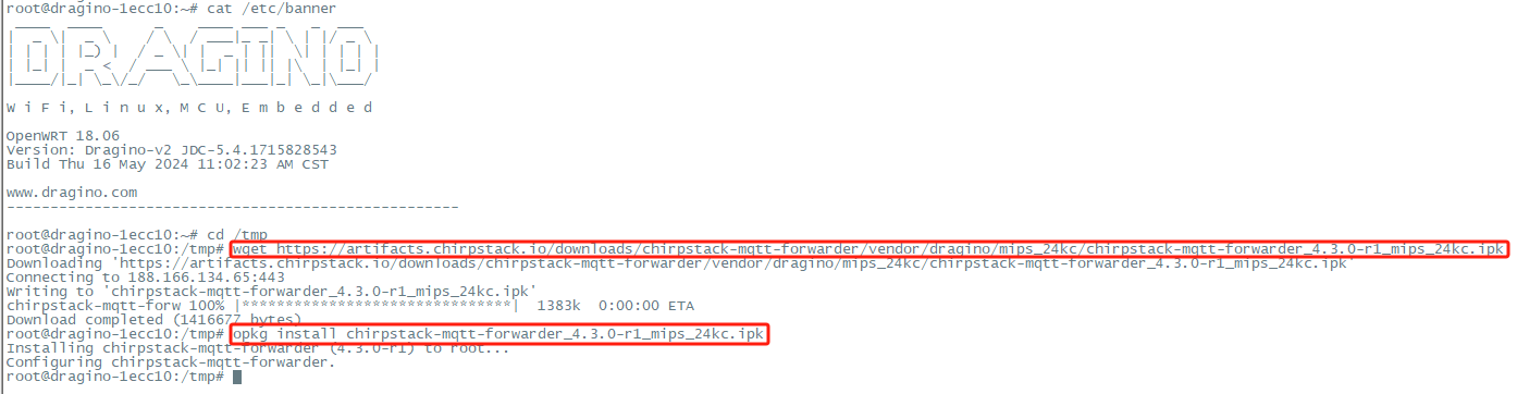
First user must login into the gateway using SSH,user can refer to the link to access the Linux console via SSH to the gateway: SSH Access for Linux console Download IPK
Use the following commands to download the latest version of the chirpstack-mqtt-forwarder package:
Install IPK
Use the opkg package-manager to install the downloaded package. Example:
opkg install chirpstack-mqtt-forwarder_4.3.0-r1_mips_24kc.ipk
Configuration
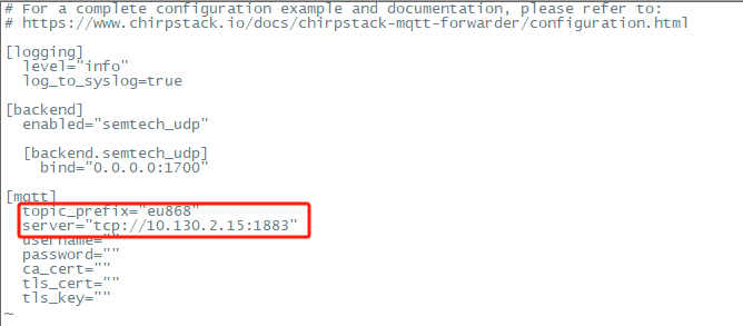
To connect the ChirpStack MQTT Forwarder to your MQTT broker, you must update the ChirpStack MQTT Forwarder configuration file.
This file is located at: /etc/chirpstack-mqtt-forwarder/chirpstack-mqtt-forwarder.toml ChirpStack MQTT Forwarder Setting:
topic_prefix --> This corresponds to the frequency of the ChirpStack server
server --> Fill in the ChirpStack server address, Example: tcp://10.130.2.15:1883
username,password,ca_cert,tls_cert,tls_key parameters should be set as required.
Use commands to modify configuration files:
vim /etc/chirpstack-mqtt-forwarder/chirpstack-mqtt-forwarder.toml
(Re)start and stop commands
Use the following commands to (re)start and stop the ChirpStack MQTT Forwarder service:
# start
/etc/init.d/chirpstack-mqtt-forwarder start
# stop
/etc/init.d/chirpstack-mqtt-forwarder stop
# restart
/etc/init.d/chirpstack-mqtt-forwarder restart
Check result
Use " logread -f **" to check the operation of ChirpStack MQTT Forwarder.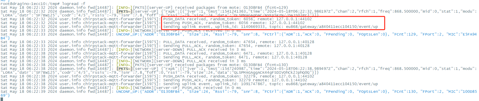
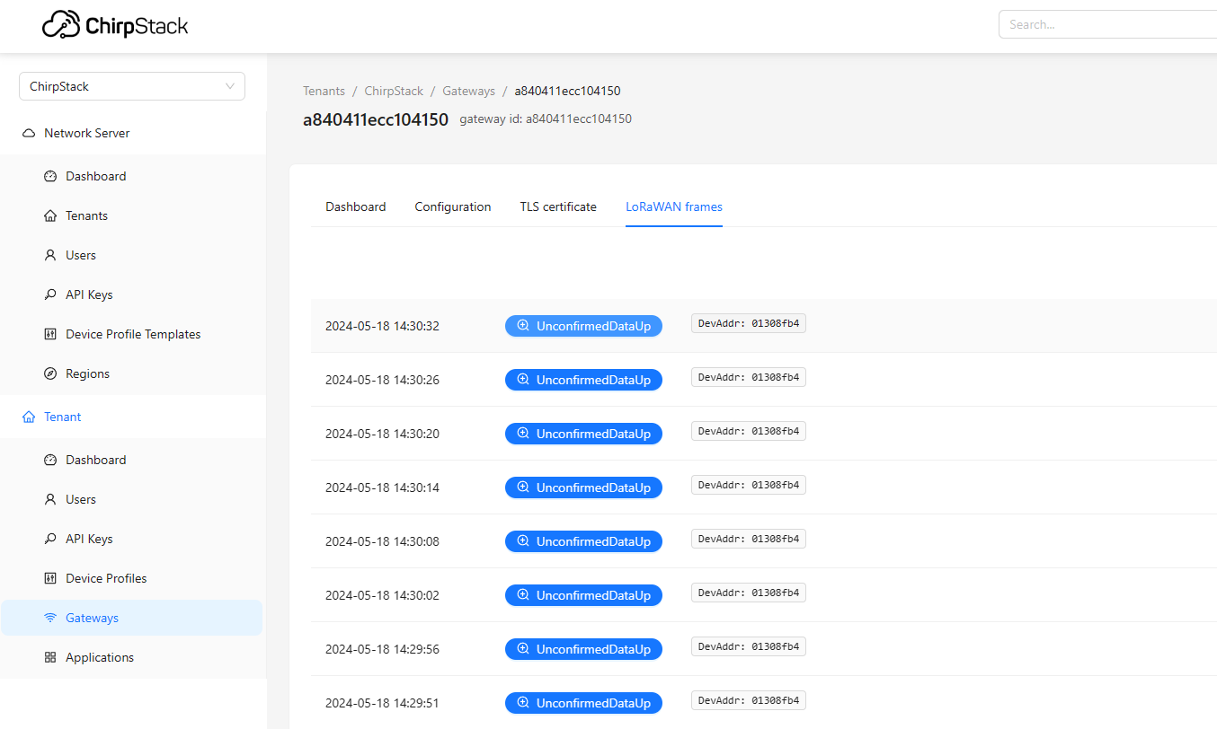
Go back to the Chirpstack server to check whether the gateway is "online" and whether the packets are displayed normally.
6.8 How to extend the gateway size of memory with USB device (SD/TF card, USB flash drive).
USB card reader plugged into the USB port of the gateway.
Access the gateway Linux Command Line.
Check the USB device
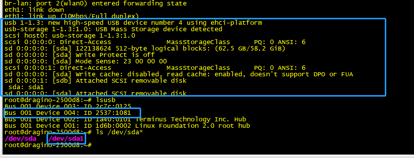
Mount the USB device
mount /dev/sda1 /mnt/

**Set up the automatic mount on boot sed -i '3cmount \dev\sda1 \mnt\' /etc/rc.local **

6.9 How to view DLOS8N GPS information
By default, when the DLOS8N GPS positioning is complete, it will be displayed in the state package on the LogRead --> System Log interface.
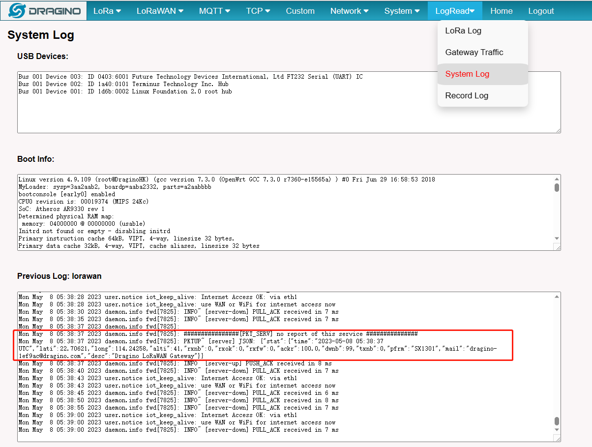
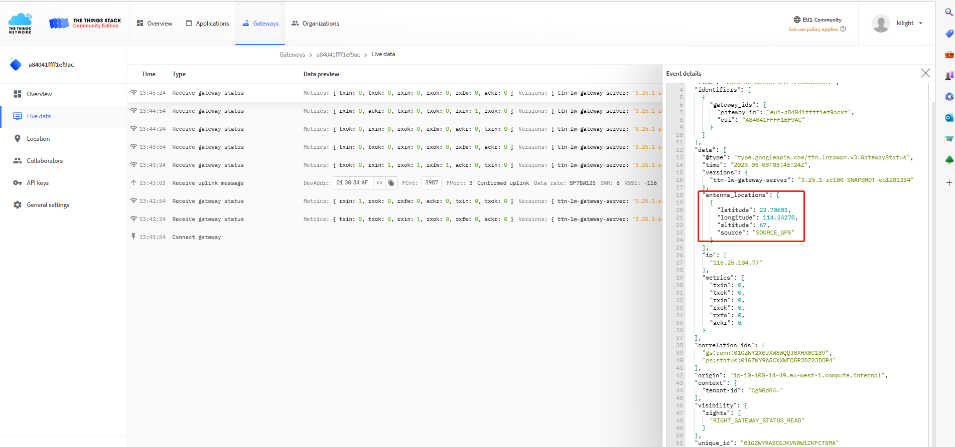
When the gateway is registered with the TTN server, the GPS information is also displayed in the TTN log.
6.10 More instructions
LoRaWAN Gateway Instruction(LoRaWAN Gateway)
7. Power Analyze
Users can refer to and calculate the power consumption of the DLOS8N in this:
| Model | Input Power | Test Mode | Current(mA) | Power Consumption(W) |
|---|---|---|---|---|
| DLOS8N | (+12V) | |||
| DLOS8N | (+12V) | Starting current | 98-154 | 1.176-1.848 |
| DLOS8N | (+12V) | No network | 155-166 | 1.86-1.992 |
| DLOS8N | (+12V) | Wifi and internet connection (LORA Start) | 150-160 | 1.8-1.92 |
| DLOS8N | (+12V) | Wifi and internet connection (LORA Start) and 4G | 160-226 | 1.92-2.712 |
| DLOS8N | (+12V) | Wifi and internet connection (LORA Start) and 4G and 32g U disk | 213-286 | 2.556-3.432 |
| DLOS8N | (+12V) | Wifi and internet connection (LORA Start) and 32g U disk | 190-216 | 2.28-2.592 |
| DLOS8N | (+12V) | 4G connection (LORA Start) | 117-227 | 1.404-2.724 |
| DLOS8N | (+12V) | Send manually | 155 | 1.86 |
| DLOS8N | (+12V) | Accept manually | 160 | 1.92 |
| POE(+12V) | ||||
| POE(+12V) | Starting current | 96-228 | 1.152-2.736 | |
| POE(+12V) | No network | 154-166 | 1.848-1.992 | |
| POE(+12V) | wifi and internet connection(LORA Start) | 154-176 | 1.848-2.112 | |
| POE(+12V) | wifi and internet connection(LORA Start)and 4G | 214-228 | 2.568-2.736 | |
| POE(+12V) | wifi and internet connection(LORA Start)and 4G and 32g U disk | 262-286 | 3.144-3.432 | |
| POE(+12V) | 4G connection (LORA Start) | 214-230 | 2.568-2.760 | |
| POE(+12V) | wifi and internet connection(LORA Start)and 32g U disk | 203-213 | 2.436-2.556 | |
| POE(+12V) | send manually | 208 | 2.496 | |
| POE(+12V) | accept manually | 164 | 1.968 |
8. Linux System
The DLOS8N is based on the OpenWrt Linux system. It is open source, and users are free to configure and modify the Linux settings.
8.1 SSH Access for Linux console
User can access the Linux console via the SSH protocol. Make sure your PC and the DLOS8N are connected to the same network, then use a SSH tool (such as putty in Windows) to access it.
**IP address: ** IP address of DLOS8N
**Port: ** 22 (via WiFi AP mode) or 2222 (via WAN Interface)
User Name: root Password: dragino (default)
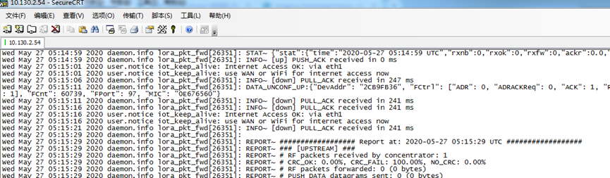
After logging in, you will be in the Linux console and can enter commands as shown below.
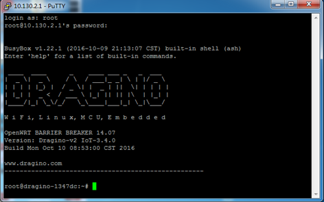
The “logread -f” command can be used to debug how system runs.
8.2 Edit and Transfer files
The DLOS8N supports the SCP protocol and has a built-in SFTP server. There are many ways to edit and transfer files using these protocols.
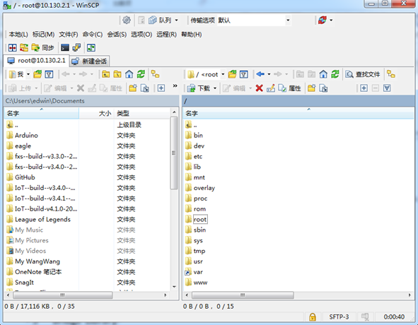
In Windows, one of the easiest methods is using the WinSCP utility.
After establishing access via WinSCP to the device, you can use an FTP style window to drag / drop files to the DLOS8N, or edit the files directly in the windows.
Screenshot is as below:
8.3 File System
The DLOS8N has a 16MB flash and a 64MB RAM. The /var and /tmp directories are in the RAM, so contents stored in /tmp and /var will be erased after rebooting the device. Other directories are in the flash and will remain after reboot.
The Linux system uses around 8MB ~10MB flash size which means there is not much room for user to store data in the DLOS8N flash.
You can use an external USB flash memory device to extend the size of flash memory for storage.
8.4 Package maintenance system
DLOS8N uses the OpenWrt OPKG package maintenance system. There are more than 3000+ packages available in our package server for users to install for their applications. For example, if you want to add the ***iperf *** tool, you can install the related packages and configure DLOS8N to use ***iperf ***.
Below are some example ***opkg *** commands. For more information please refer to the OPKG package maintain system (https://oldwiki.archive.openwrt.org/doc/techref/opkg)
In Linux Console run: root@dragino-169d30:~# opkg update // to get the latest packages list
root@dragino-169d30:~# opkg list // shows the available packages
**root@dragino-169d30:~# opkg install iperf ** // install iperf
The system will automatically install the required packages as shown below.
root@dragino-169d30:/etc/opkg# opkg install iperf
Installing iperf (2.0.12-1) to root…
*Downloading *http://downloads.openwrt.org/snapshots/packages/mips_24kc/base/iperf_2.0.12-1_mips_24kc.ipk
Installing uclibcxx (0.2.4-3) to root…
*Downloading *http://downloads.openwrt.org/snapshots/packages/mips_24kc/base/uclibcxx_0.2.4-3_mips_24kc.ipk
Configuring uclibcxx.
Configuring iperf.
9. Upgrade Linux Firmware
We keep improving the DLOS8N Linux side firmware for new features and bug fixes. Below are the links for reference.
- Latest firmware: LoRa Gateway Firmware,
( http://www.dragino.com/downloads/index.php?dir=LoRa_Gateway/DLSO8N/Firmware)
- Change Log: Firmware Change Log.
( http://www.dragino.com/downloads/downloads/LoRa_Gateway/DLOS8N/Firmware/ChangeLog )
The file named as ** xxxxx–xxxxx-squashfs-sysupgrade.bin **is the upgrade Image. There are different methods to upgrade, as below.
9.1 Upgrade via Web UI
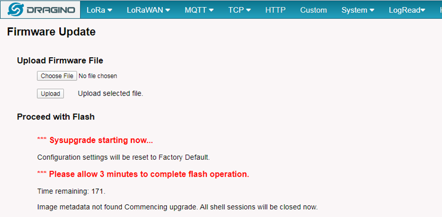
Go to the page: Web --> System --> Firmware Upgrade
Select the required image and click Flash Image. The image will be uploaded to the device, and then click Process Update to upgrade.
NOTE: You normally need to uncheck the Preserve Settings checkbox when doing an upgrade to ensure that there is no conflict between the old settings and the new firmware. The new firmware will start up with its default settings.
The system will automatically boot into the new firmware after upgrade.
9.2 Upgrade via Linux console
SCP the firmware to the system** /var** directory and then run
** root@OpenWrt:~# /sbin/sysupgrade –n /var/Your_Image NOTE**: it is important to transfer the image in the /var directory, otherwise it may exceed the available flash size.
10. OTA System Update
DLOS8N supports system auto update via OTA, please see this URL for the detail of this feature.
11. FAQ
11.1 How can I configure for a customized frequency band?
See below link for how to customize frequency band: How to customized LoRaWAN frequency band
11.2 Can I connect DLOS8N to LORIOT?
Yes, the set up instruction is here: Notes for LORIOT
11.3 Can I make my own firmware for the gateway, where can I find the source code?
Yes, You can make your own firmware for the DLOS8N for branding purposes or to add customized applications.
The source code and compile instructions can be found at: https://github.com/dragino/openwrt_lede-18.06
11.4 Can I use 868Mhz version for 915Mhz bands?
It is possible but the distance will be very short, you can select US915 frequency band in 868Mhz version hardware. It will work but you will see the performance is greatly decreased because the 868Mhz version has an RF filter for band 863~870Mhz, all other frequencies will have high attenuation.
12. Trouble Shooting
12.1 I get kernel error when install new package, how to fix?
In some cases, when installing a package with opkg, it will generate a kernel error such as below due to a mismatch I the kernel ID:
root@dragino-16c538:~# opkg install kmod-dragino2-si3217x_3.10.49+0.2-1_ar71xx.ipk
Installing kmod-dragino2-si3217x (3.10.49+0.2-1) to root…
Collected errors:
* satisfy_dependencies_for: Cannot satisfy the following dependencies for kmod-dragino2-si3217x:
* kernel (= 3.10.49-1-4917516478a753314254643facdf360a) *
* opkg_install_cmd: Cannot install package kmod-dragino2-si3217x.
In this case, you can use the –force-depends option to install such package as long as the actual kernel version is the same.
Opkg install kmod-dragino2-si3217x_3.10.49+0.2-1_ar71xx.ipk –force-depends
12.2 How to recover the DLOS8N if the firmware crashes
Please follow this instruction to recover your gateway: Recover Gateway
12.3 I configured DLOS8N for WiFi access and lost its IP. What to do now?
The DLOS8N has a fall-back IP address on its WAN port. This IP is always enabled so you can use the fall-back IP to access DLOS8N no matter what the WiFi IP is. The fall back IP is useful for connecting and debug the unit.
Note: fallback IP can be disabled in the WAN and DHCP page. Steps to connect via fall back IP:
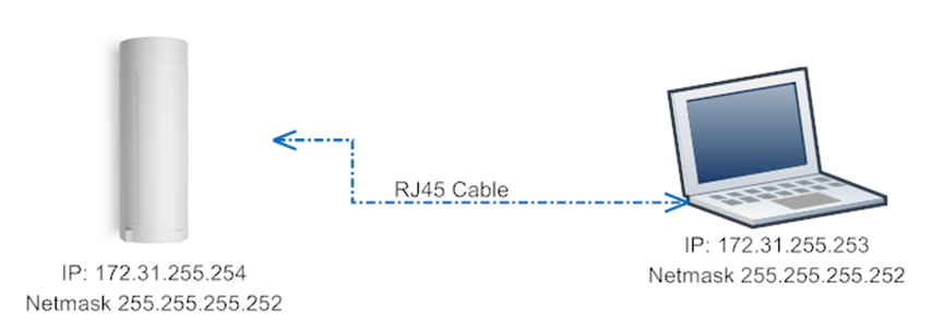
1. Connect PC's Ethernet port to DLOS8N's WAN port
2. Configure PC's Ethernet port has IP: 172.31.255.253 and Netmask: 255.255.255.252
As below photo:
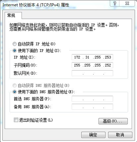
3. In the PC, use IP address 172.31.255.254 to access the DLOS8N via Web or Console.
Please note the latest firmware uses port 8000 for http and 2222 for ssh access.
12.4 Why does the gateway reboot every 15 minutes without Internet?
Check whether Internet Detect is enabled on the System-->General interface.
Internet Detect is enabled by default. When there is no gateway network, it will reboot after 15 minutes.
12.4 How to check the cellular network service type
The cellular module used by the DLOS8N gateway is EC25-E, an LTE Cat 4 module launched by Quectel Communications. It supports 4G networks and is also compatible with 3G and 2G.
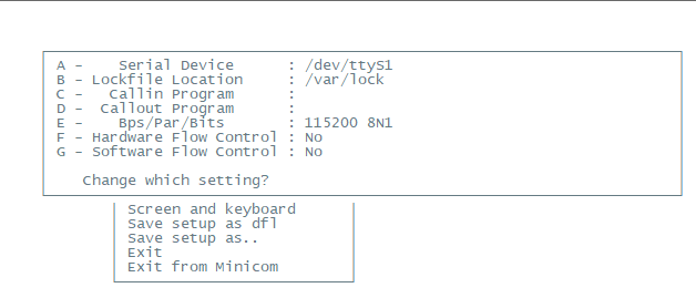
Users can access the gateway CLI and run the minicom command to get the configuration interface.
Enter the minicom command, then select the option ''serial port setup". minicom -s

And then, change the setting:
Serial Device : /dev/ttyModemAT Bps/Par/Bits : 9600 8N1 Note: Enter the corresponding letter to change the configuration, like A,B,C
Enter AT+QNWINFOin the interface to get the cellular network service type

For example, displaying FDD LTE means that the device has successfully connected to the 4G network, and **LTE BAND 8 **means the currently used 4G frequency band.
12.5 Why does cellular display and work normally after the gateway was updated to the latest firmware version?
Due to lgw--build-v5.4.1746500086-20250506-1102 version switch pppd cellular dialing to qmi
The two 4G versions differ, so you cannot select the option to Preserver settings.
If you have selected the option to Preserver settings and the upgrade has been completed, you can reset the gateway and the gateway will be restored.

13. Order Info
PART: DLOS8N-XXX-YYY XXX: Frequency Band
- ** 868** : valid frequency: 863Mhz ~ 870Mhz. for bands:
EU868、RU864、IN865、KZ865 - ** 915**: valid frequency: 902Mhz ~ 928Mhz. for bands:
US915、AU915、AS923、KR920
YYY: 4G Cellular Option
- EC25-E: EMEA, Korea, Thailand, India.
- EC25-AFX: America:Verizon, AT&T(FirstNet), U.S.Cellular; Canada:Telus
- EC25-AUX: Latin America, New Zeland, Taiwan
- EC25-J: Japan, DOCOMO, SoftBank, KDDI
More info about valid bands, please see EC25-E product page.
14. Packing Info
Package Includes:
- DLOS8N LoRaWAN IoT Gateway x 1
- Stick Antenna for LoRa RF part. Frequency is one of 470 or 868 or 915Mhz depends the model ordered
- Packaging with environmental protection paper box
Dimension and weight:
- Device Size: 26 x 9 x 8.5 cm
- Weight: 450g
- Package Size: 49 x 19.5 x 12 cm
- Weight: 2.5kg
15. Support
- Try to see if your questions already answered in the wiki.
- Support is provided Monday to Friday, from 09:00 to 18:00 GMT+8. Due to different timezones we cannot offer live support. However, your questions will be answered as soon as possible in the before mentioned schedule.
- Provide as much information as possible regarding your enquiry (product models, accurately describe your problem and steps to replicate it etc) and send a mail to: support@dragino.com
0