LPS8v2 – LoRaWAN Indoor Gateway User Manual
LPS8v2 – LoRaWAN Indoor Gateway User Manual
1. Introduction
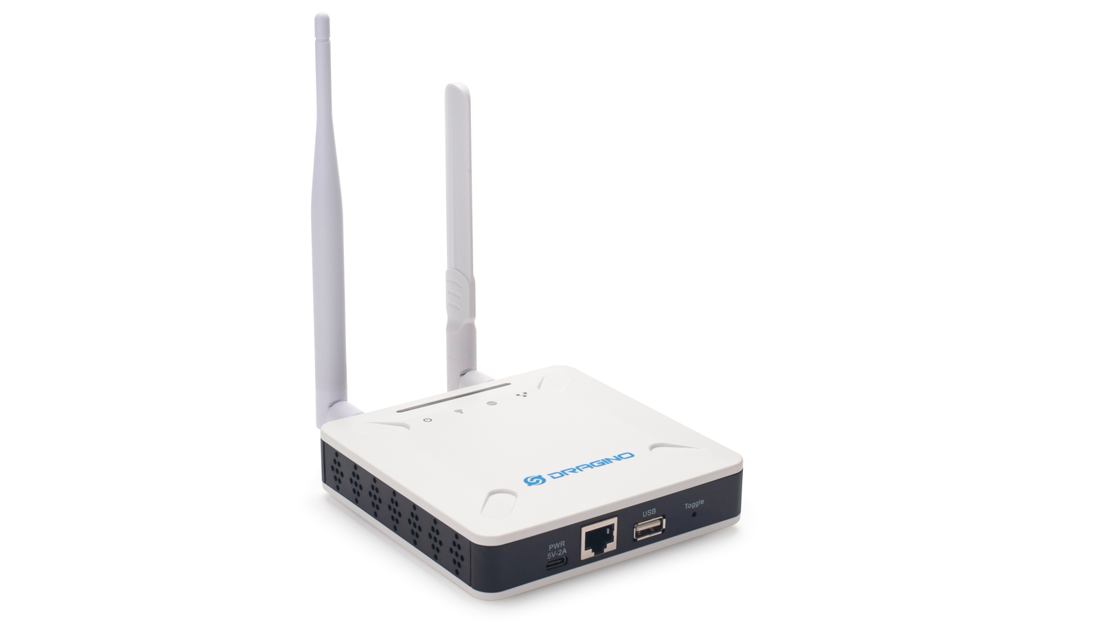
1.1 What is LPS8v2
The LPS8v2 is an open-source LoRaWAN Gateway. It lets you bridge LoRa wireless network to an IP network via WiFi , Ethernet or Cellular Network (via Optional 4G module). The LoRa wireless allows users to send data and reach extremely long ranges at low data rates.
The LPS8v2 is fully compatible with LoRaWAN protocol. It supports different kinds of LoRaWAN Network Connections such as: Semtech UDP Packet Forwarder, LoRaWAN Basic Station, ChirpStack MQTT Bridge, and so on. This makes LPS8V2 work with most LoRaWAN platforms in the market.
LPS8v2 also includes a built-in LoRaWAN Server ChirpStack-V4 and IoT server Node-red, which provide the possibility for the system integrator to deploy the IoT service without cloud service or 3rd servers.
Different countries use different LoRaWAN frequency bands. LPS8v2 has these bands pre-configured. Users can also customize the frequency bands to use in their own LoRa network.
LPS8v2 supports remote management. System Integrator can easy to remote monitor the gateway and maintain it.
1.2 Specifications
Hardware System:
- CPU: Quad-core Cortex-A7 1.2Ghz
- RAM: 512MB
- eMMC: 4GB
Interface:
- 10M/100M RJ45 Ports x 1
- Multi-Channel LoRaWAN Wireless
- WiFi 802.11 b/g/n
- Sensitivity: -140dBm
- Max Output Power: 27dBm
Operating Condition:
- Work Temperature: -20 ~ 70°C
- Storage Temperature: -20 ~ 70°C
- Power Input: 5V, 2A, DC
1.3 Features
- Open Source Debian system
- Managed by Web GUI, SSH via WAN or WiFi
- Remote Management
- Auto-provisioning for batch deployment and management
- LoRaWAN Gateway
- 10 programmable parallel demodulation paths
- Pre-configured to support different LoRaWAN regional settings.
- Allow customizing LoRaWAN regional parameters.
- Different kinds of LoRaWAN Connections such as
- Semtech UDP Packet Forwarder
- LoRaWAN Basic Station
- ChirpStack-Gateway-Bridge (MQTT)
- Built-in ChirpStack local LoRaWAN server
- Built-in Node-Red local Application server
1.4 LED Indicators
LPS8-V2 has totally four LEDs, They are:
➢ Power LED: This RED LED will be solid if the device is properly powered
➢ ETH LED: This RGB LED will blink GREEN when the ETH port is connecting
➢ SYS LED: This RGB LED will show different colors in different states:
                 ✓    **SOLID GREEN:** The device is alive with a LoRaWAN server connection.

                 ✓    **BLINKING GREEN:** a) Device has internet connection but no LoRaWAN Connection. or b) Device is in booting stage, in this stage, it will BLINKING GREEN for several seconds and then with BLINKING GREEN together

                 ✓**    SOLID RED:** Device doesn't have an Internet connection.
➢ WIFI LED: This LED shows the WIFI interface connection status.
1.5 Button Instruction
LPS8-V2 has a black toggle button, which is:
***➢ *Long press 4-5s : **the gateway will reload the Network and Initialize wifi configuration
* * **LED status: ** ETH LED will BLINKIND BULE Until the reload is finished.
**➢ Long press more than 10s: **the gateway will restore the factory settings.
**LED status: ** ETH LED will SOLID BULE Until the restore is finished.
Note: Restoring factory Settings does not erase data from the LPS8-V2 built-in server
See this link for steps on how to clear data from the built-in server: How to reset the built-in server
When the gateway restores the factory settings is complete,
The WiFi configuration will enable WiFi Access Point by default.
The other configuration will be restored to the default configuration.
2. Access and Configure LPS8-V2
2.1.1 Find IP address of LPS8-V2
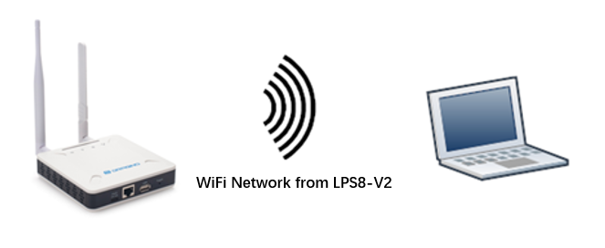
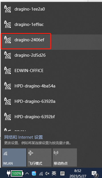
Method 1: Connect via LPS8-V2 WiFi
Since software version 230524,At the first boot of LPS8-V2, it will auto generate a WiFi network called ***dragino-xxxxxx ***with password:
dragino+dragino
User can use a PC to connect to this WiFi network. The PC will get an IP address 10.130.1.xxx and the LPS8-V2 has the default IP 10.130.1.1
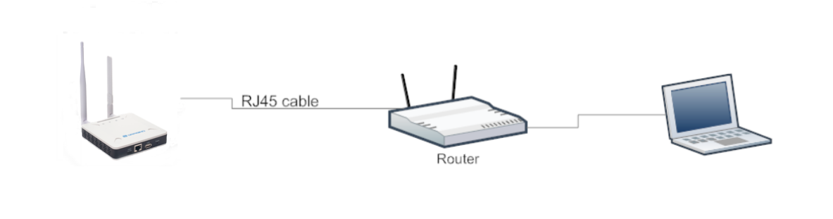
Method 2: Connect via Ethernet with DHCP IP from the router
Connect the LPS8-V2 Ethernet port to your router and LPS8-V2 can obtain an IP address from your router. In the router's management portal, you should be able to find what IP address the router has assigned to the LPS8-V2.
You can also use this IP to connect.
Method 3: Connect via LPS8-V2 Fallback IP
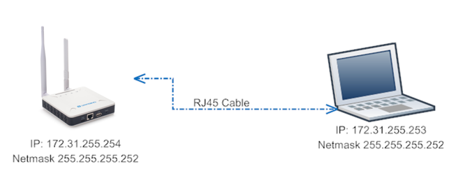
Steps to connect via fallback IP:
1. Connect the PC's Ethernet port to LPS8-V2's WAN port
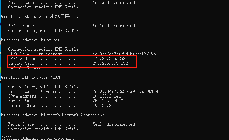
2. Configure PC's Ethernet port has IP: 172.31.255.253 and Netmask: 255.255.255.252
Settings --> Network & Internet --> Ethernet --> Change advanced sharing options --> Double-click"Ethernet" --> Internet Protocol Version 4 (TCP/IPv4)
As in the below photo:
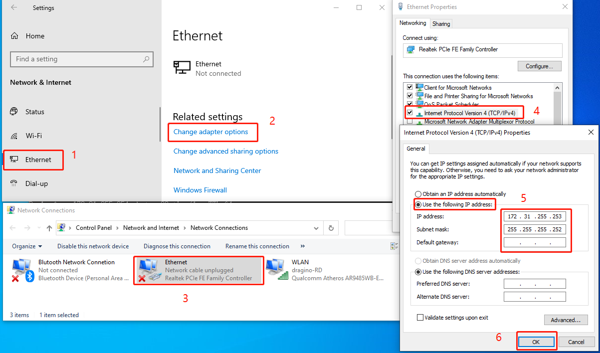
Configure computer Ethernet port steps video: fallback ip.mp4
If you still can't access the LPS8-V2 fallback ip, follow this connection to debug : Trouble Shooting
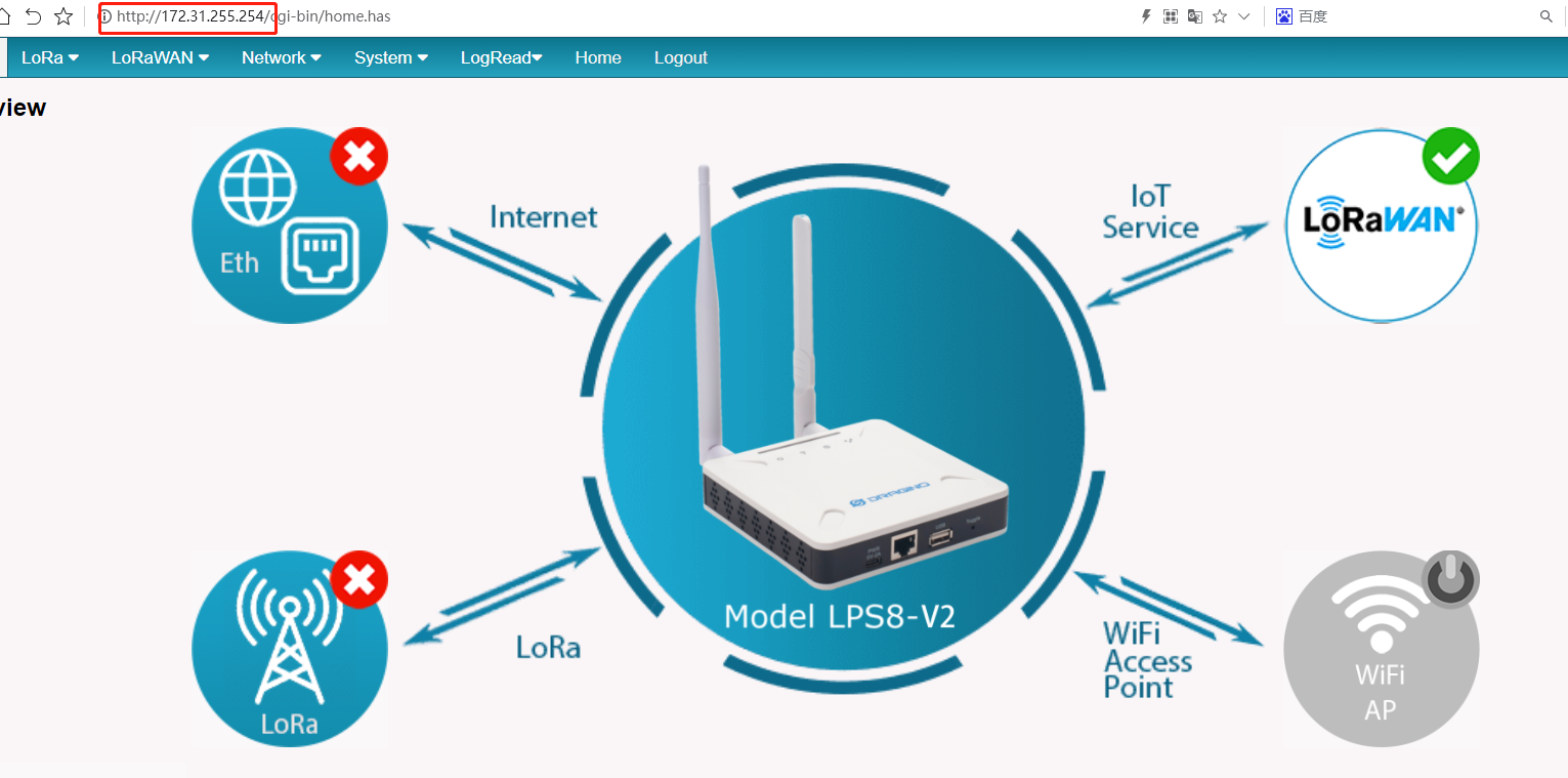
3. In the PC, use IP address 172.31.255.254 to access the LPS8-V2 via Web or Console.
Method 4: Connect via WiFi with DHCP IP from the router
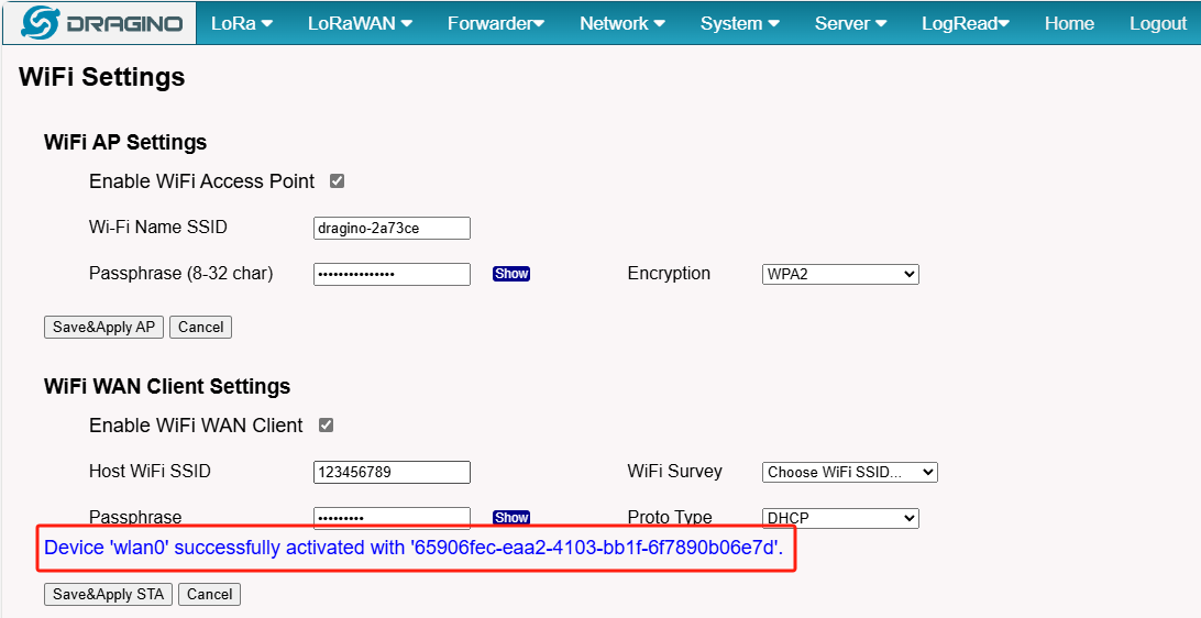
Fill in the WiFi information by checking the box and clicking Save&Apply
Wi-Fi configuration successful
2.1.2 Access Configure Web UI
Web Interface
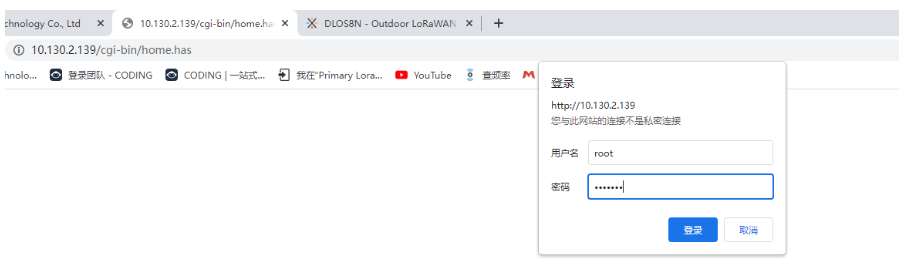
Open a browser on the PC and type the LPS8-V2 ip address (depends on your connect method)
***http://IP_ADDRESS *** or http://172.31.255.254(Fallback IP)
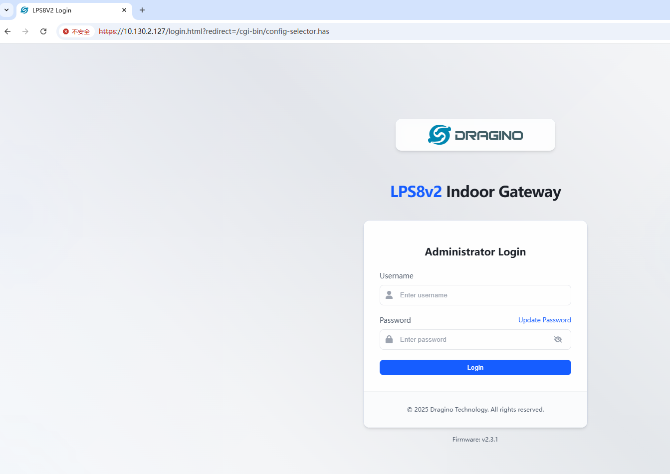
You will see the login interface of LPS8-V2 as shown below.
The account details for Web Login are:
User Name: root Password: dragino
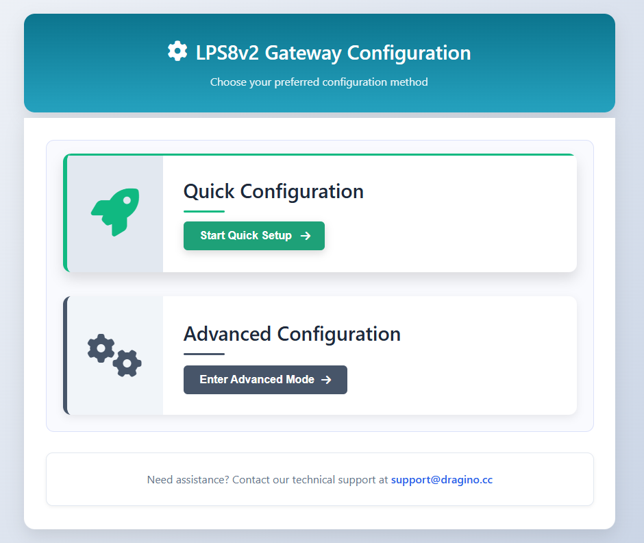
3. Quick Start
After logging into the gateway, users can select the **Quick Configuration **option to streamline the configuration process. This guide offers an easy and efficient way to get your device up and running. It covers all the essential steps, from initial connections to basic settings, ensuring that you can start using the system with minimal effort and without the need for complex configurations.
For a more detailed walkthrough and advanced configuration options, please refer to the LSP8v2 Quick Configuration Guide
4. Advanced Configuration
4.1 Typical Network Setup
4.1.1 Overview
LPS8-V2 supports flexible network set up for different environment. This section describes the typical network topology can be set in LPS8-V2. The typical network set up includes:
-
WAN Port Internet Mode
-
WiFi Client Mode
-
Cellular Mode
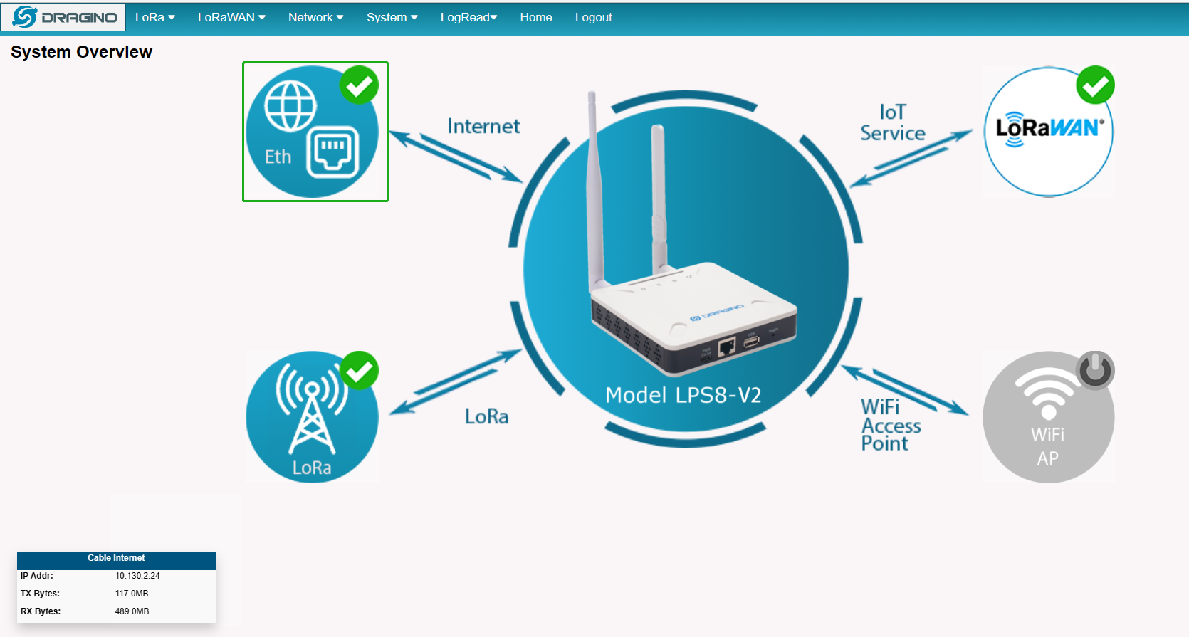
4.1.2 Use WAN port to access Internet
By default, the LPS8-V2 is set to use the WAN port to connect to an upstream network. When you connect the LPS8-V2's WAN port to an upstream router, LPS8-V2 will get an IP address from the router and have Internet access via the upstream router. The network status can be checked in the home page:
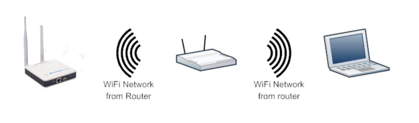
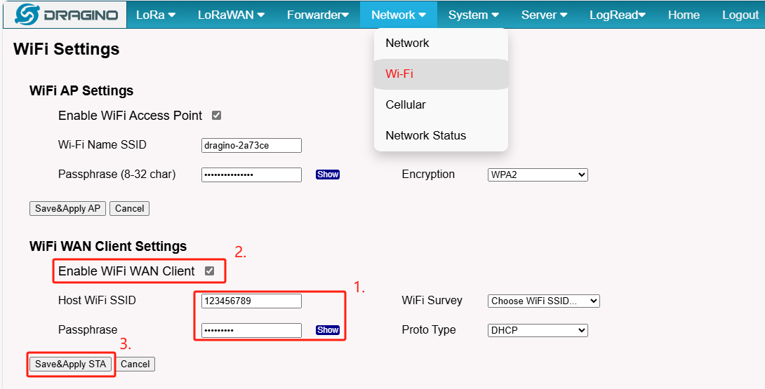
4.1.3 Access the Internet as a WiFi Client
In the WiFi Client Mode, LPS8-V2 acts as a WiFi client and gets DHCP from an upstream router via WiFi.
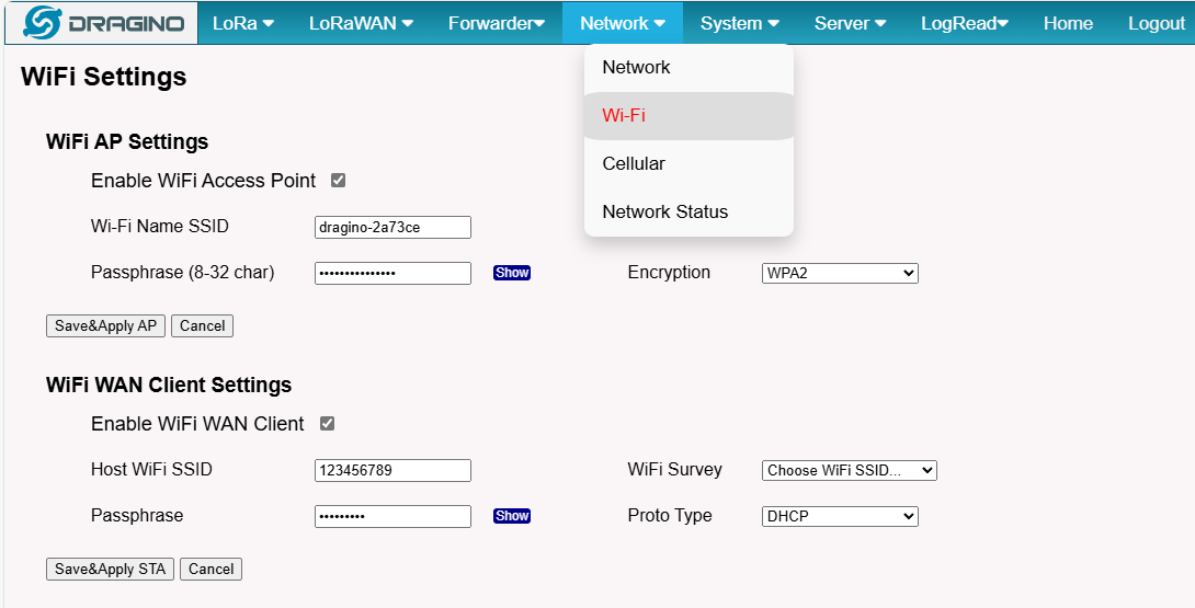
The settings for WiFi Client is under page Network --> Wi-Fi

In the WiFi Survey Choose the WiFi AP, and input the Passphrase then click** Save & Apply** to connect.
4.1.4 Use built-in 4G modem for internet access
Since Hardware version HP0C 1.4
Users can see whether LPS8v2 has EC25 on the label of the gateway to determine whether there is 3G/4G Cellular modem.
If the LPS8-V2 has 3G/4G Cellular modem, user can use it as main internet connection or back up.
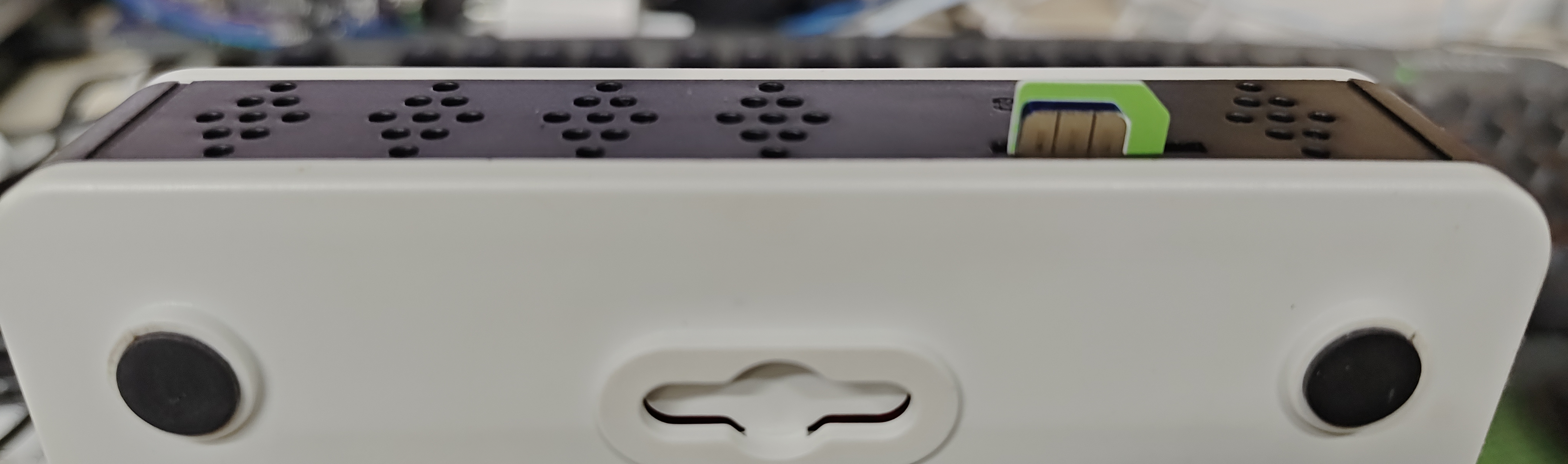
First, install the Micro SIM card as below direction
Second, Power off/ ON LPS8-V2 to let it detect the SIM card.
The set up page is Network --> Cellular
While use the cellular as Backup WAN, device will use Cellular for internet connection while WAN port or WiFi is not valid and switch back to WAN port or WiFi after they recover.
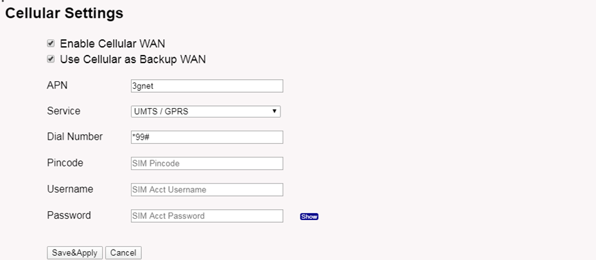
Note: In most cases, the user simply types in the APN and checks the enable checkbox, without typing Pincode, Username, or Password settings.
When cellular fails to connect or has problems, users can refer to this link to Trouble Shooting:How to Trouble Shooting if Cellular connection fails
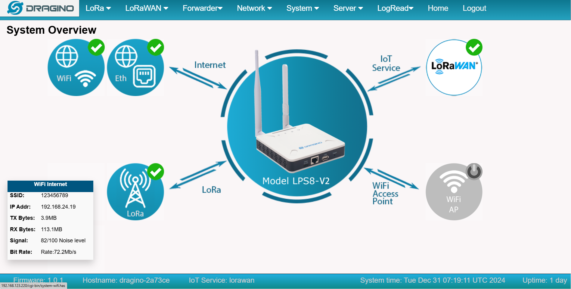
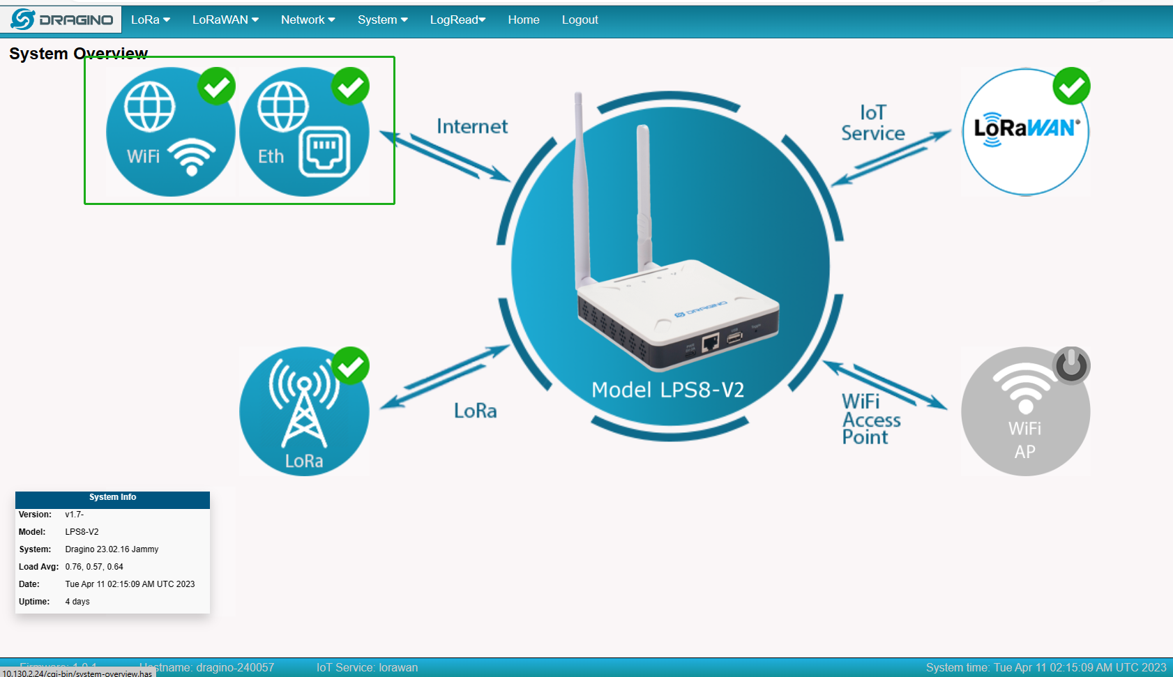
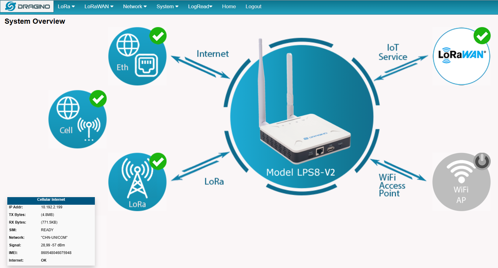
4.1.5 Check Internet connection
In the home page, we can check the Internet connection.
- GREEN Tick
 : This interface has Internet connection.
 - Yellow Tick
 : This interface has IP address but don't use it for internet connection.
 - RED Cross
 : This interface doesn't connected or no internet.
4.2 The LPS8-V2 is registered and connected to The Things Network
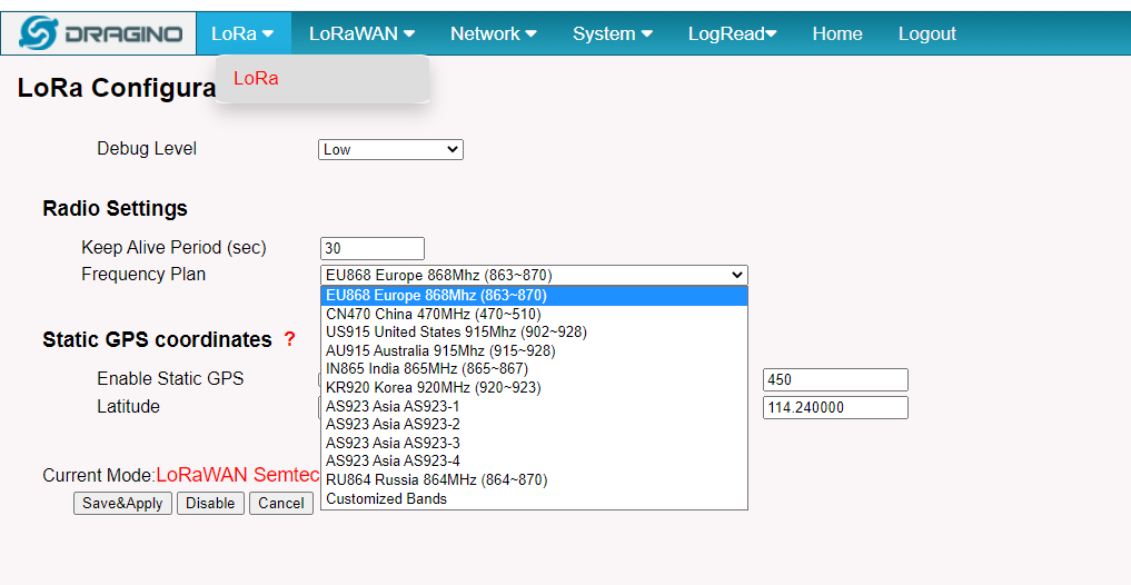
4.2.1 Select your area frequency
First, you need to set the frequency plan in LPS8-V2 to match the end node we use, so to receive the LoRaWAN packets from the LoRaWAN sensor.
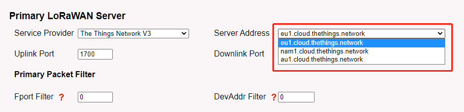
4.2.2 Get the only gateway EUI
Every LPS8-V2 has a unique gateway id. The ID can be found on LoRaWAN Semtech page:
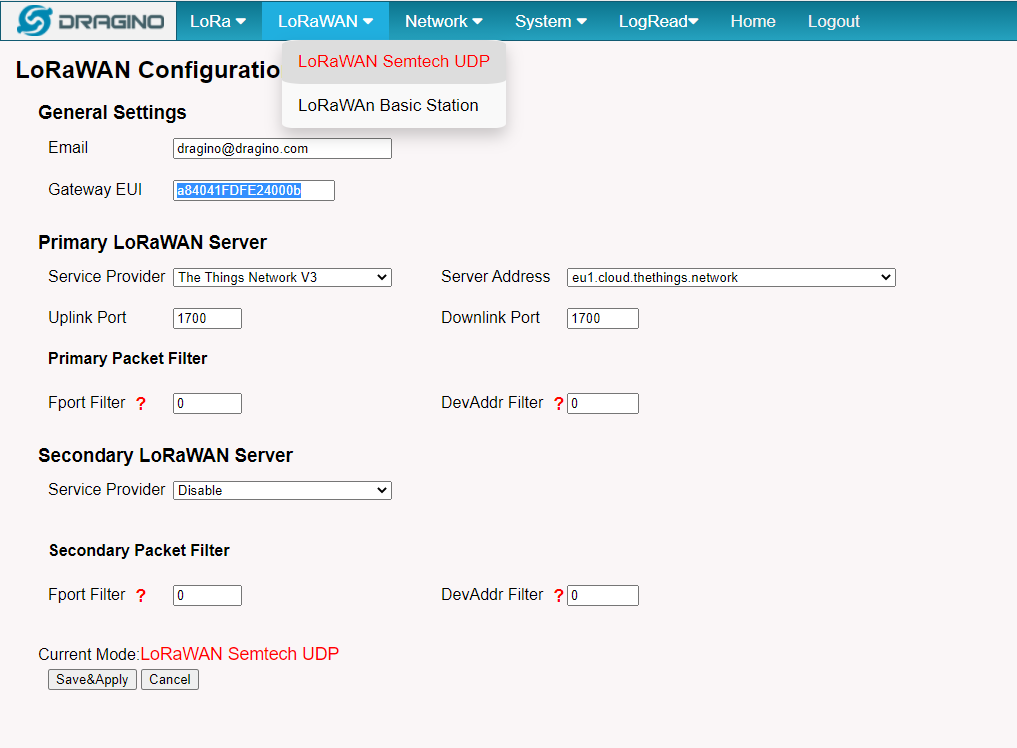
Note: Choose the cluster that corresponds to a specific Gateway server address ➢ Europe 1: corresponding Gateway server address: eu1.cloud.thethings.network ➢ North America 1: corresponding Gateway server address: **nam1.cloud.thethings.network ➢ Australia 1: ** corresponding Gateway server address: au1.cloud.thethings.network ➢ Legacy V2 Console: TTN v2 shuts down in December 2021
4.2.3 Register the gateway to The Things Network
Login to The Things Network
https://console.cloud.thethings.network/
Add the gateway
Get it online
5. Web Configure Pages
5.1 Home
Shows the system running status:
5.2 LoRa Settings
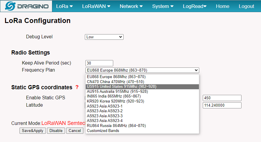
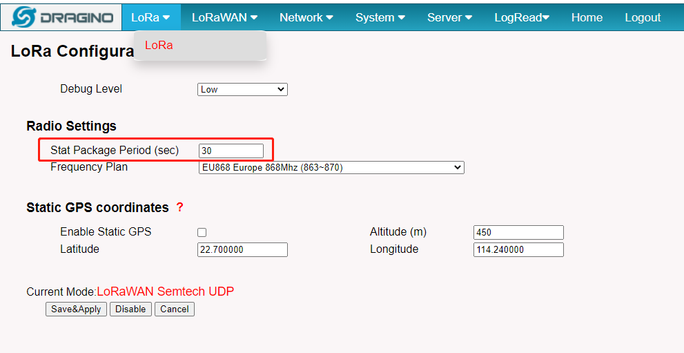
5.2.1 LoRa --> LoRa
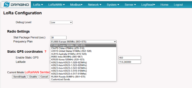
This page shows the LoRa Radio Settings. There is a set of default frequency bands according to LoRaWAN protocol, and users can customize the band* as well.
Different LPS8v2 hardware versions can support different frequency ranges:
- 868: valid frequency: 863Mhz ~ 870Mhz. for bands:
EU868、RU864、IN865、KZ865 - 915: valid frequency: 902Mhz ~ 928Mhz. for bands:
US915、AU915、AS923、KR920
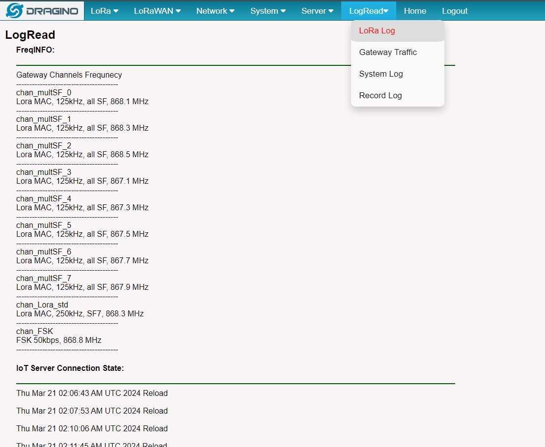
After the user choose the frequency plan, the user can see the actual frequency is used by checking the page LogRead --> LoRa Log
Note *: See this instruction for how to customize the frequency band: How to customized LoRaWAN frequency band - DRAGINO
5.3 LoRaWAN Settings
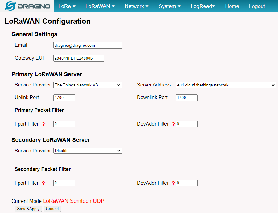
4.3.1 LoRaWAN --> LoRaWAN Semtech UDP
This page is for the connection set up to a general LoRaWAN Network server such as TTN, ChirpStack, etc.
5.3.2 LoRaWAN --> LoRaWAN Basic Station
This page is for the connection set up to the TTN Basic Station, AWS-IoT, etc.
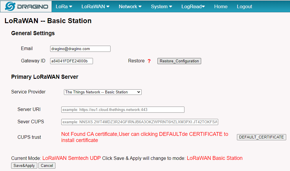
Please see this instruction to know more detail and a demo for how to use of LoRaWAN Basic Station: Use of LoRaWAN Basic Station - DRAGINO
5.4 Forwarder
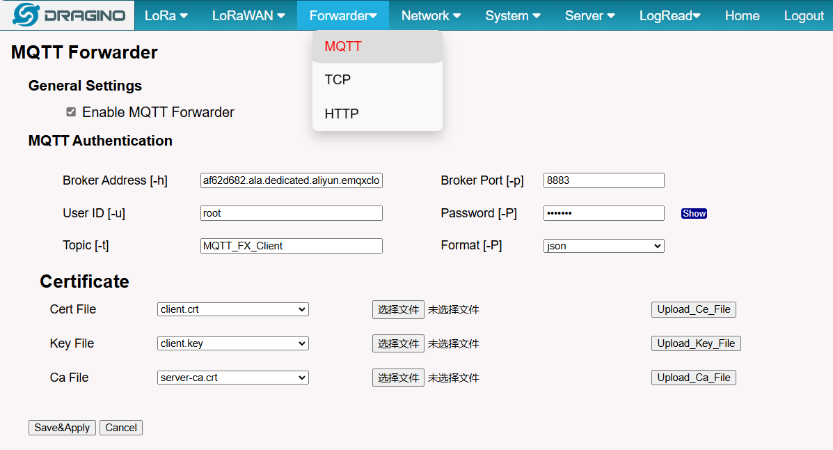
5.4.1 Forwarder --> MQTT Forwarder
In the latest version, MQTT Forwarder functionality has been added to the LPS8V2 gateway by default
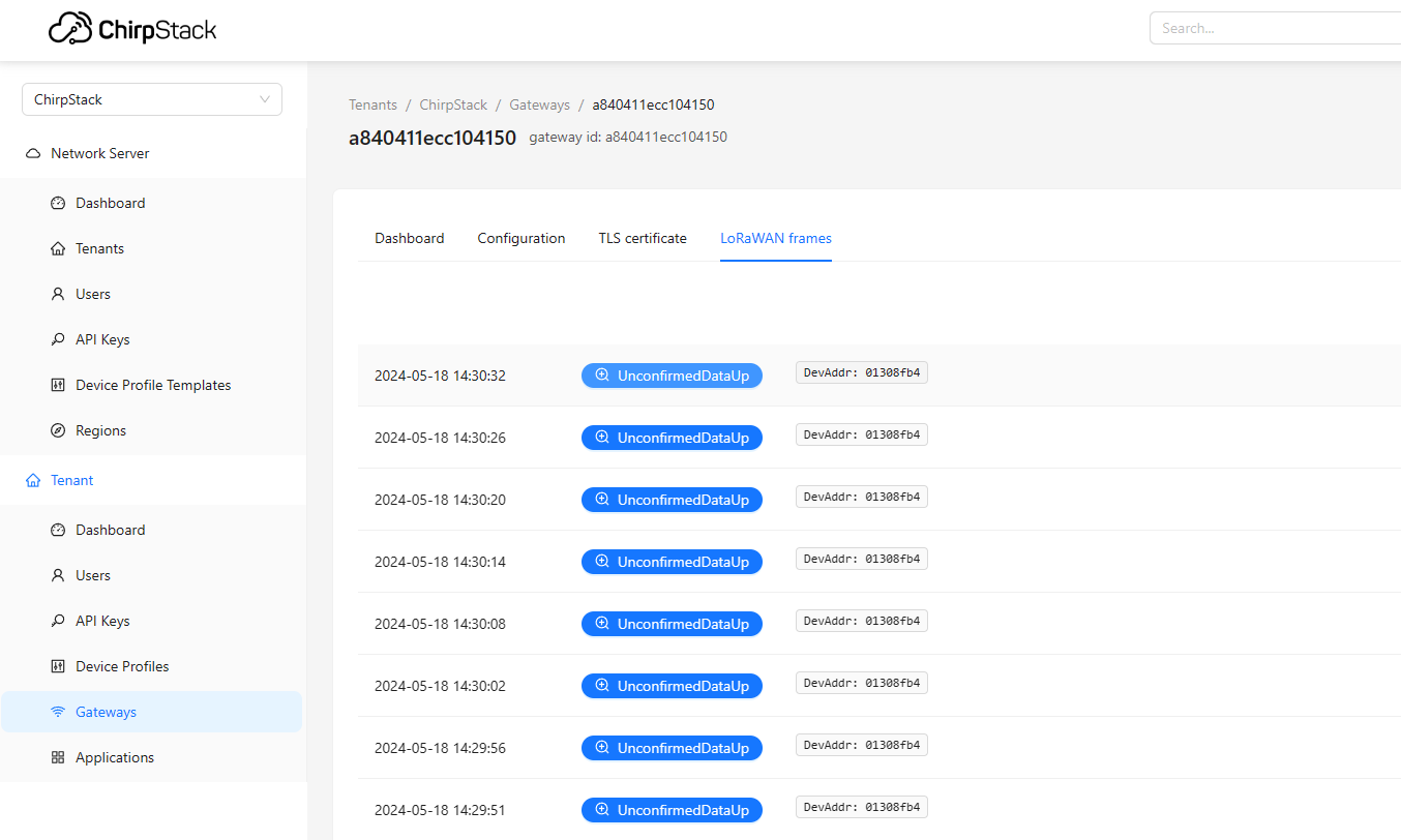
Users can configure the MQTT Forwarder on the Forwarder-->MQTT interface, and when the configuration is successful, it will forward the sensor data of the lorawan server chirpstack built in LPS8v2
For a detailed example of this feature, see this link:MQTT Forward Instruction - DRAGINO
5.5 Network Settings
5.5.1 Network --> WiFi
Users can configure the wifi WAN and enable Wifi Access Point on this interface
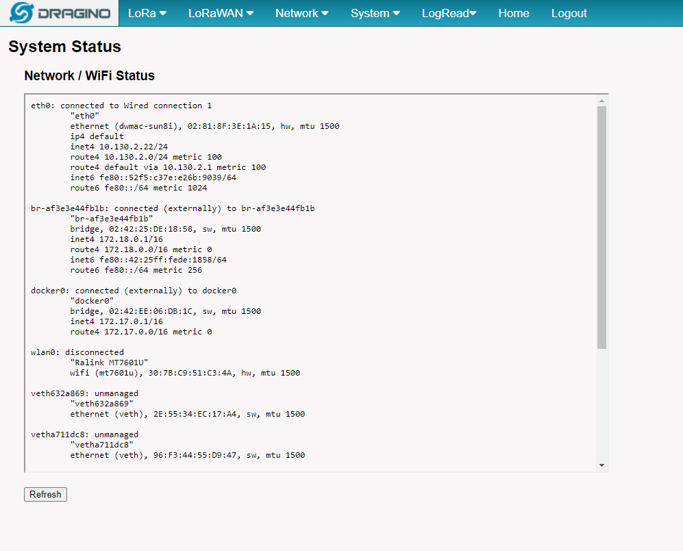
5.5.2 Network --> System Status
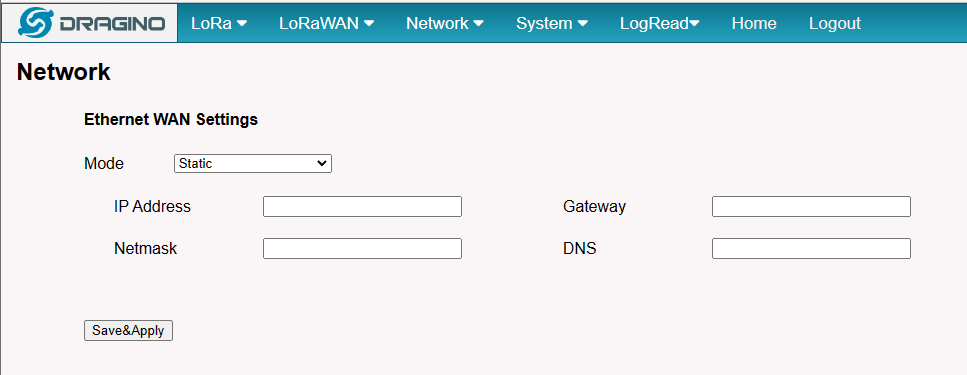
5.5.3 Network --> Network
In the Network --> Network interface, Users can set the Ethernet WAN static ip address.
5.5.4 Network --> Cellular
In the Network --> Cellular interface, Users can Enable Cellular WAN and configure Celluar.
Note: APN cannot be empty.
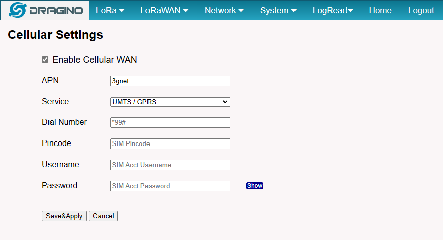
After the configuration is complete, return to the Home interface and put the mouse on the Cell icon to check the Cellular state.
Note: Known bugs: 4g consumes a lot of data which has been fixed by the package: dragino-ui-230716
When cellular fails to connect or has problems, users can refer to this link to Trouble Shooting:How to Trouble Shooting if Cellular connection fails
5.6 System
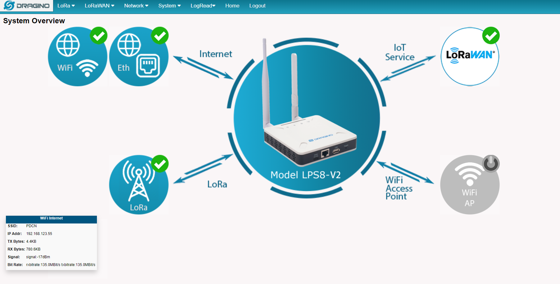
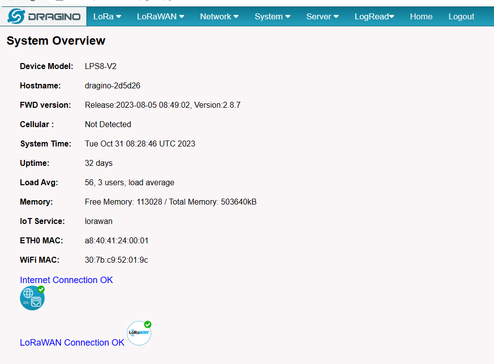
5.6.1 System --> System Overview
Shows the system info:
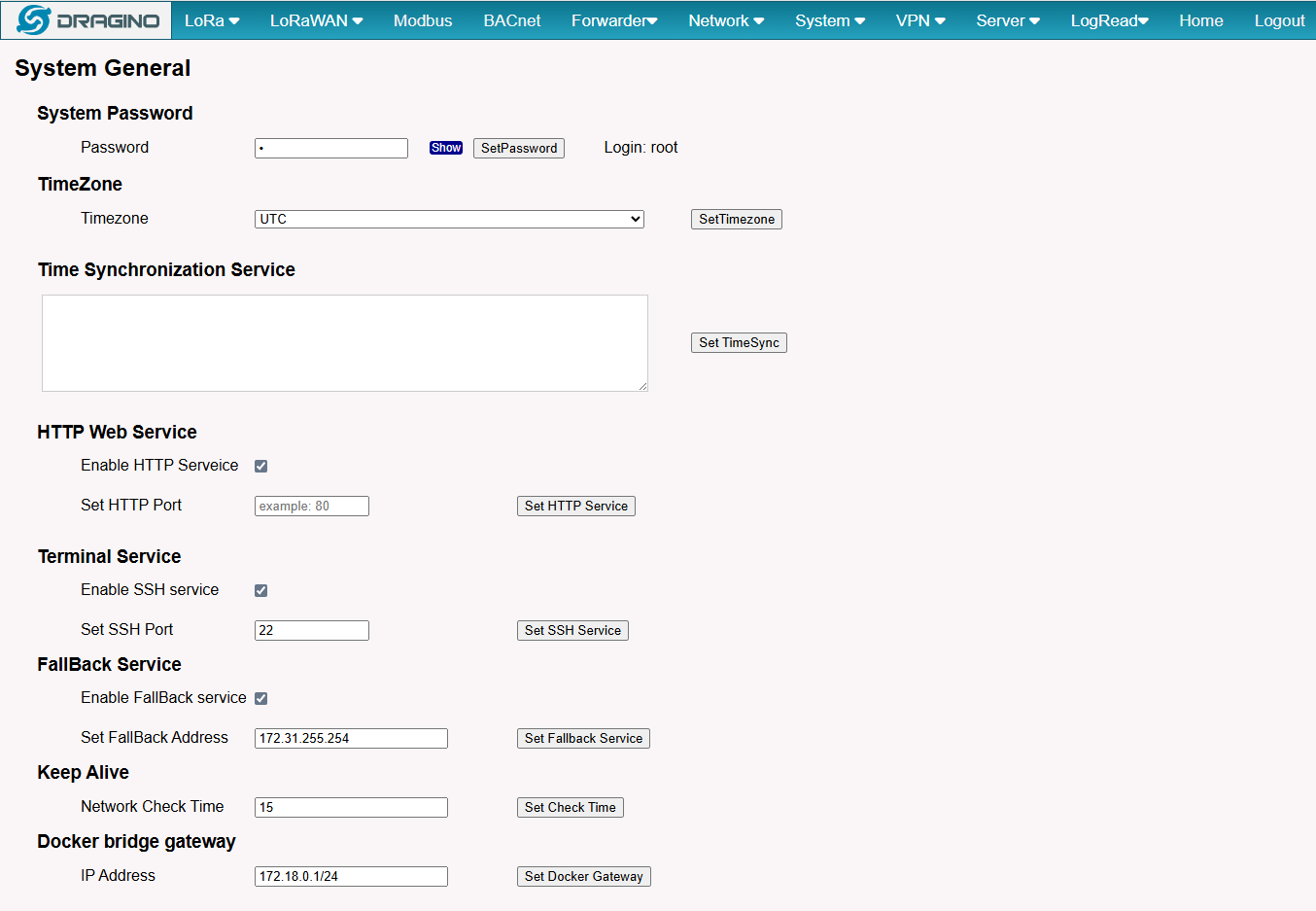
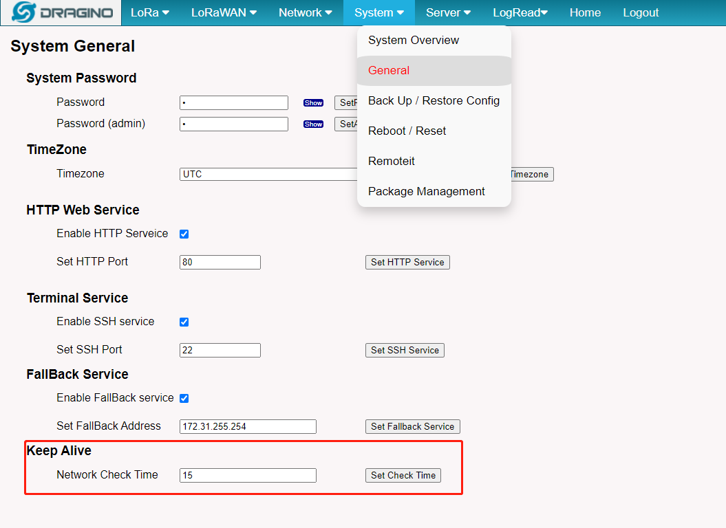
5.6.2 System --> System General
In the System-> System General interface, Users can customize the configuration System Password and set Timezone.
In addition, Users can customize the FallBack IP address.
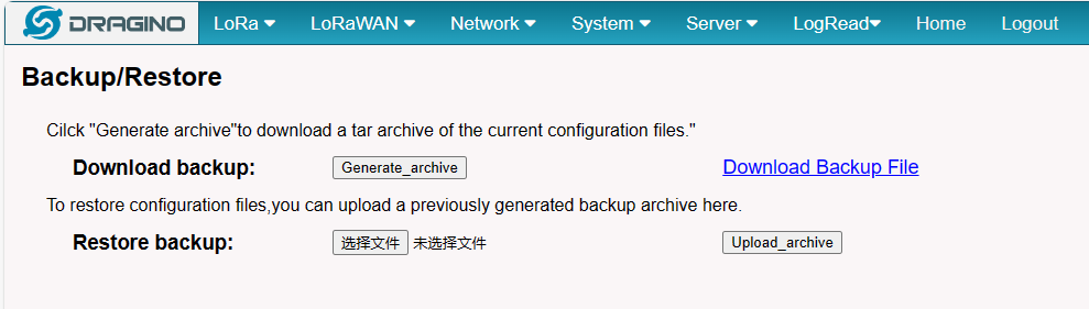
5.6.3 System --> Backup/Restore
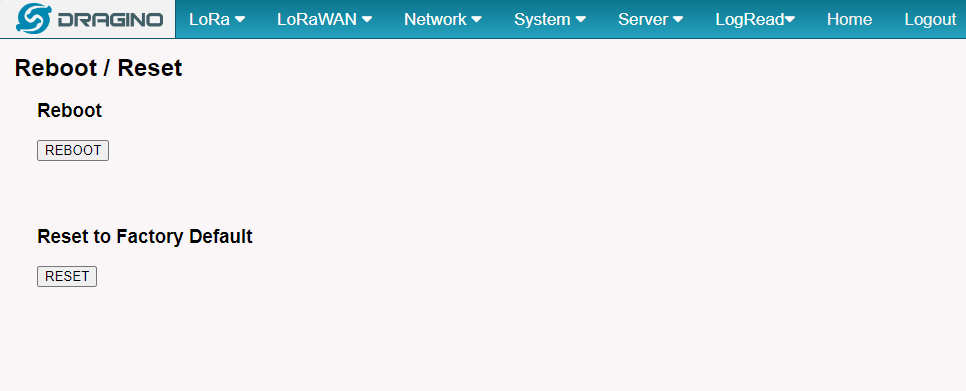
5.6.4 System --> Reboot / Reset
In the System-> Reboot / Reset interface, users can can restart or reset the gateway.
ETH LED will SOLID BULE Until the restore is finished.
When the gateway restores the factory settings is complete,
The WiFi configuration will enable WiFi Access Point by default.
The other configuration will be restored to the default configuration.
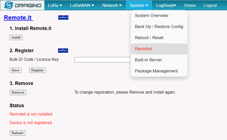
5.6.5 System --> Remoteit
In the System-> Remoteit interface, users can configure the gateway to be accessed remotely via Remote.it.
the users can refer to this link to configure them: Monitor & Remote Access Gateway
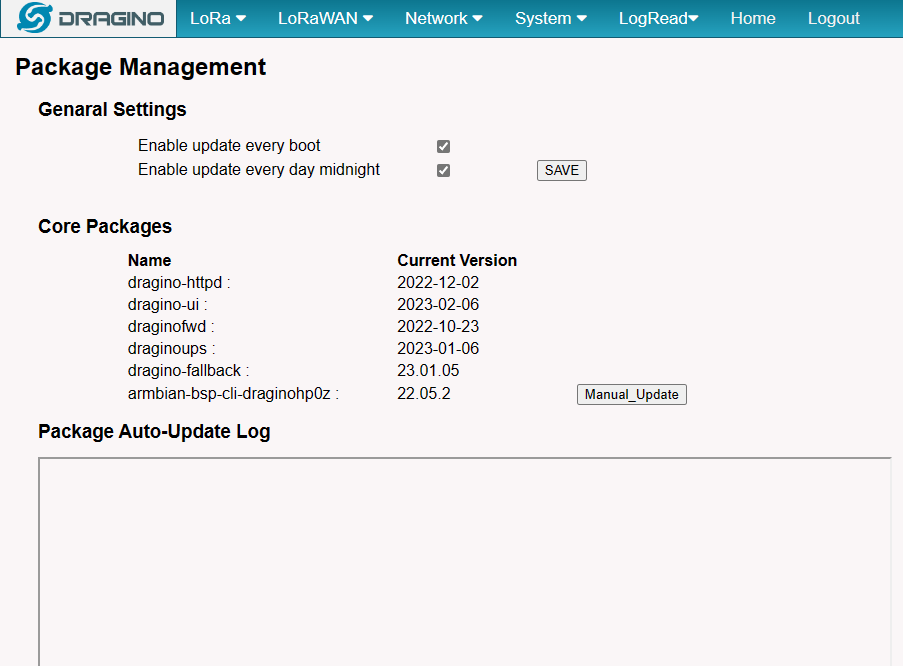
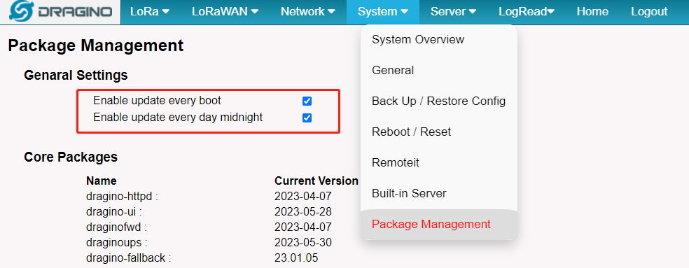
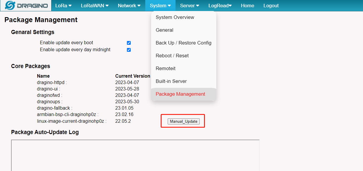
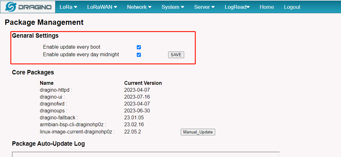
5.6.6 System --> Package Management
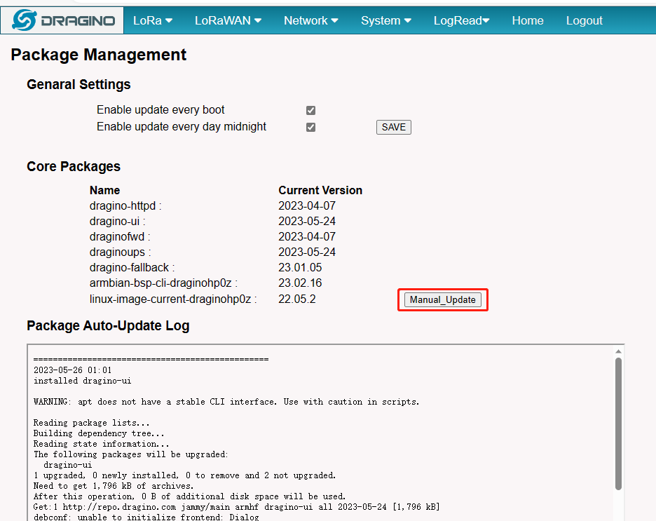
In the System --> Package Management interface, Users can check the current version of Core Packages.
5.7 Logread
5.7.1 LoRa Log
In the Lograde --> LoRa Log page, The users can view information about the gateway lora channel and the status of the IoT connection
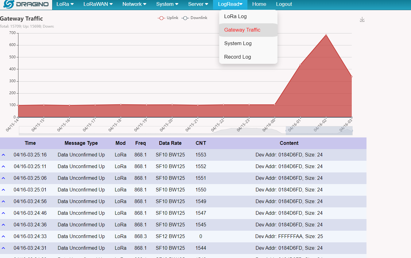
4.7.2 Gateway Traffic
In the Lograde --> Gateway Traffic page, The users can view sensor packages about Recent LoRa uplink/downlink/Join requests
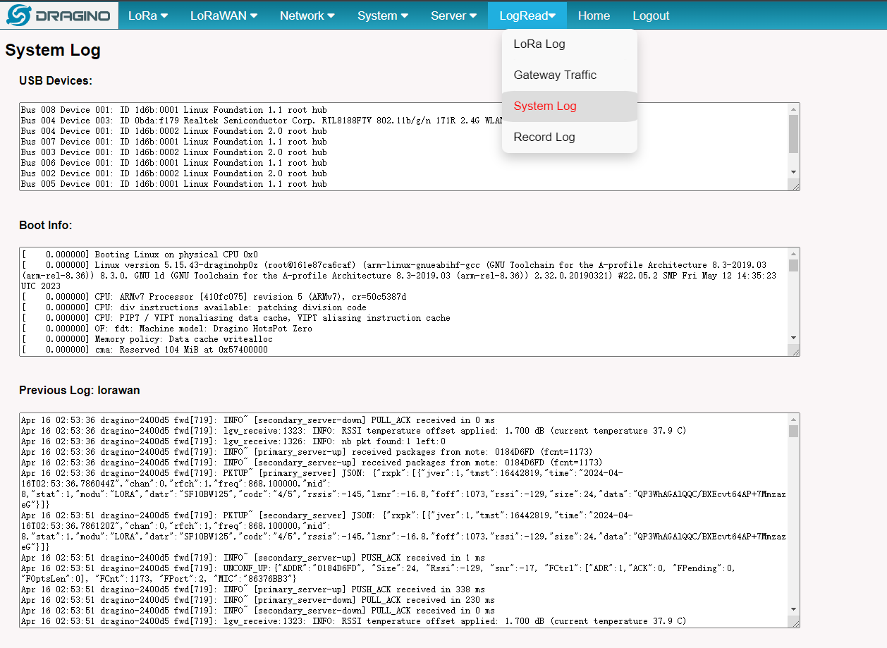
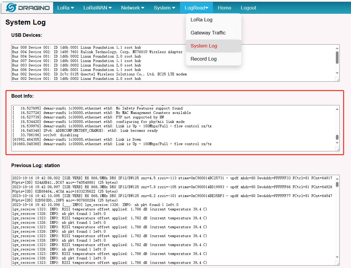
4.7.3 System Log
In the Lograde --> System Log page, The users can view information about the gateway system
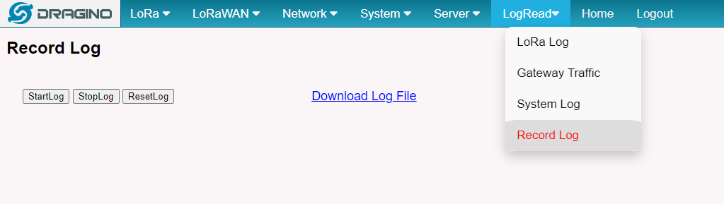
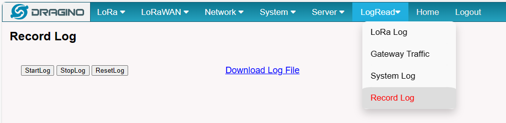
4.7.4 Record Log
In the Lograde --> Recod Log page, The users can record the gateway curren running log.
5. Build-in Server
After the v1.7-230606 version, the LPS8-V2 default factory pre-installed the LoRaWAN Server: ChirpStack-V4, Application Server: Node-Red.
Note: LPS8V2 has built-in chirpstack based on Docker, so customers do not need to install it manually again
1). LoRaWAN Network Server: ChirpStack-V4
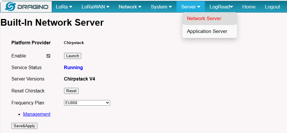
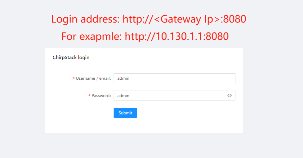
Note: The user can access the ChirpStack-V4 via click the 'Launch' button, and the login account: admin/admin
For more information on server operations see Register LPSV2 to the built-in Chirpstack
2). Application Network Server: Node-Red
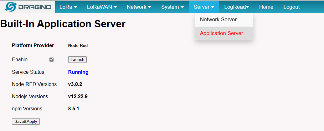
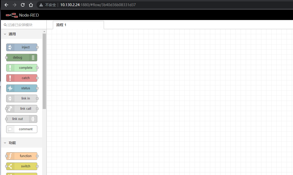
Note: The user can access the Node-RED via click the 'Launch' button
3). Troubleshooting:
** If the URL does not jump properly.**
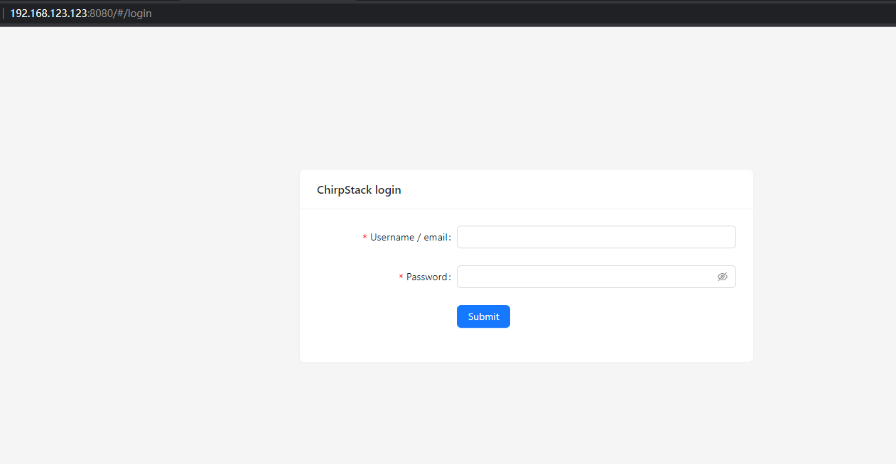
            For the ChirpStack, you can use the local IP address and the port is **8080** to access it.

            For the Node-Red, you can use the local IP address and the port is **1880** to access it.
** How to install InfluxDB, Garfana.**
The LPS8V2 is not pre-installed with InfluxDB and Garfana, the users can install them, see [InfluxDB](/docs/wiki/configuration/gateway/armbian-base-devices-os-advance-guide/)
** How to upgrade the gateway node.js to the latest version.**
The user can upgrade nodejs, see [Upgrade Nodejs](/docs/wiki/configuration/gateway/armbian-base-devices-os-advance-guide/)
** How to batch register device on the built-in Chirpstack network server**
The user can register devices in batch on the gateway Web UI, see [Batch Register](/docs/wiki/iot-lorawan-server/network-server/chirpstack/)
** Why my gateway is not Chirpstack?**
After June '23, the default factory LPS8V2 pre-installed Chirpstack-V4 instead of The Things Stack, the users can migrate to Chistack-V4, see **[Change TTN Stack v3 to ChirpStack](/docs/wiki/LoRaWAN-Gateway/indoor-gateways/hp0c/)**
** How to disable the built-in server**
Use the following commands to start and stop the TTNv3 service:
# start systemctl start ttnstack
# stop systemctl stop ttnstack
# enable systemctl enable ttnstack
#disable systemctl disable ttnstack
Use the following commands to start and stop the Node-Red service:
# start systemctl start nodered
# stop systemctl stop nodered
# enable systemctl enable nodered
#disable systemctl disable nodered
** How to choose the Chirpstack server frequency SubBand ** The user has to choose a SubBand if using: CN470、US915、AU915、AS923
Note: Since the subbands of the Chirpstack are counted from 0, us915_1 of the Chirpstack is equal to US915 FSB2, so if your LoRa Rdio is using the US915 FSB2 you have to choose the us915_1 as the Chirpstack FSB.
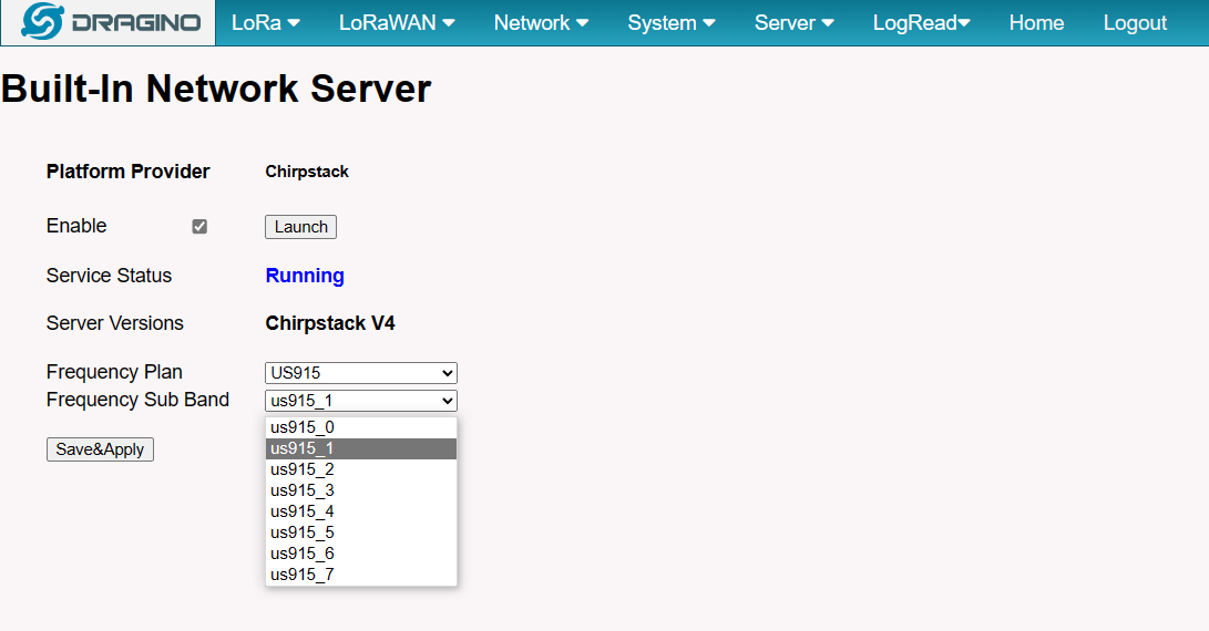
When the configuration is complete, click** "Save&Apply"**.
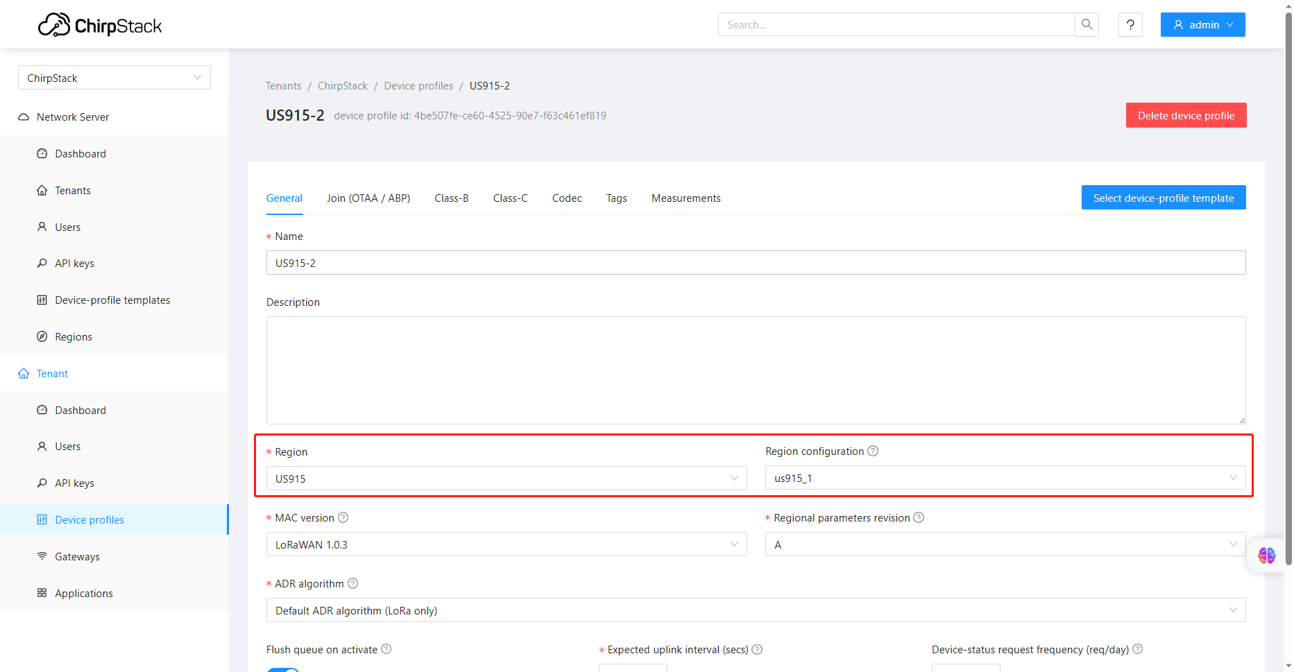
Note: When adding the device profile, the selected Region configuration is also calculated from 0, so setting it to us915_1 corresponds to US915 Sub Band 2.
6. Watch Dog
The watchdog will guard the LPS8V2 to avoid the need to perform a reboot manually after down occurs
LPS8-V2 supports the Watch Dog but is not enabled by the previous releases(2023-11-24 )
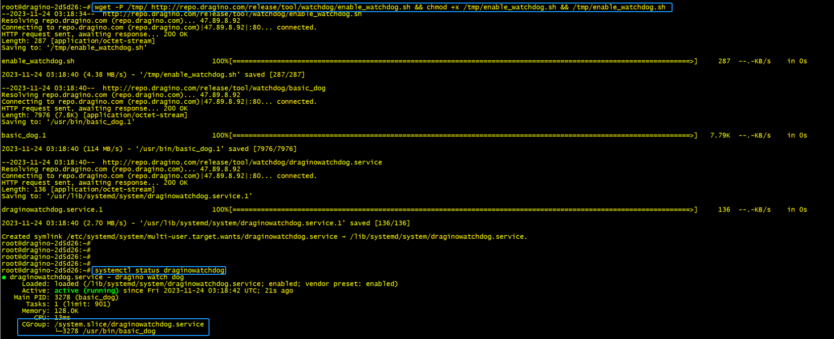
The uses can be via the below method to enable Watch Dog:
wget -P /tmp/ http://repo.dragino.com/release/tool/watchdog/enable_watchdog.sh && chmod +x /tmp/enable_watchdog.sh && /tmp/enable_watchdog.sh
7. How users can access LPS8-V2 using serial USB
USB TTL to LPS8-V2 Connection:
Port 1 of the UART on the LPS8-V2 is GND
TXD <---> UART RXD (Gray line) RXD <---> UART TXD (White line) GND <---> GND (Black line) LPS8v2 UART connection photo
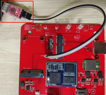
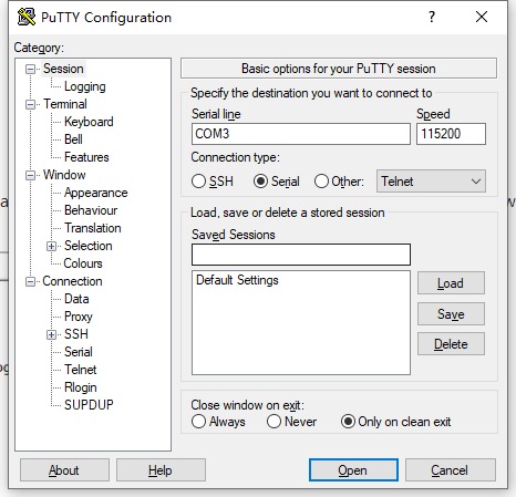
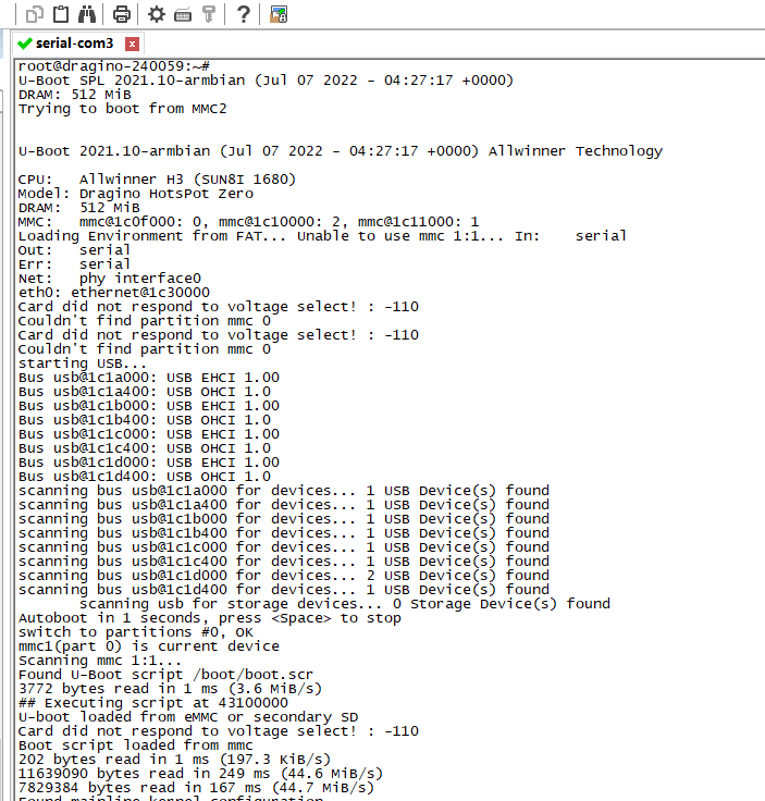
In the PC,you can use the serial port tool(such as putty in Windows), you need to set the serial baud rate to 115200 to access the serial console for LPS8v2. LPS8v2 will output system info once power on as below:
9. OTA System Update
LPS8v2 supports system auto-update via OTA, please see this URL for the detail of this feature.
9.1 Auto-update method
The default, each gateway will enable the auto-update function.
this function will be triggered every boot and every midnight.
Users can enable/disable it via Web Page
9.2 Manual upgrade method
1). Using the Linux command to upgrade the system
apt update && apt install *dragino*
2). Upgrade the system via the Web page button of "Manual Update"
**Note: this method needs about 10 mins, so you will get the log after 10 mins. **
10. How do I view gateway logs
10.1 LoRaWAN Log:
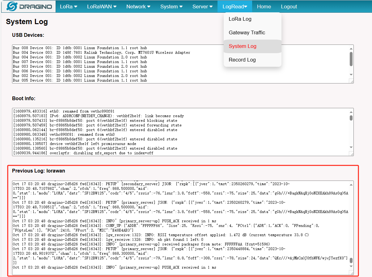
Semtech UDP Log :
When the gateway starts LoRaWAN Semtech UDP, users can check the logs of the Semtech UDP in the LogRead --> System Log interface
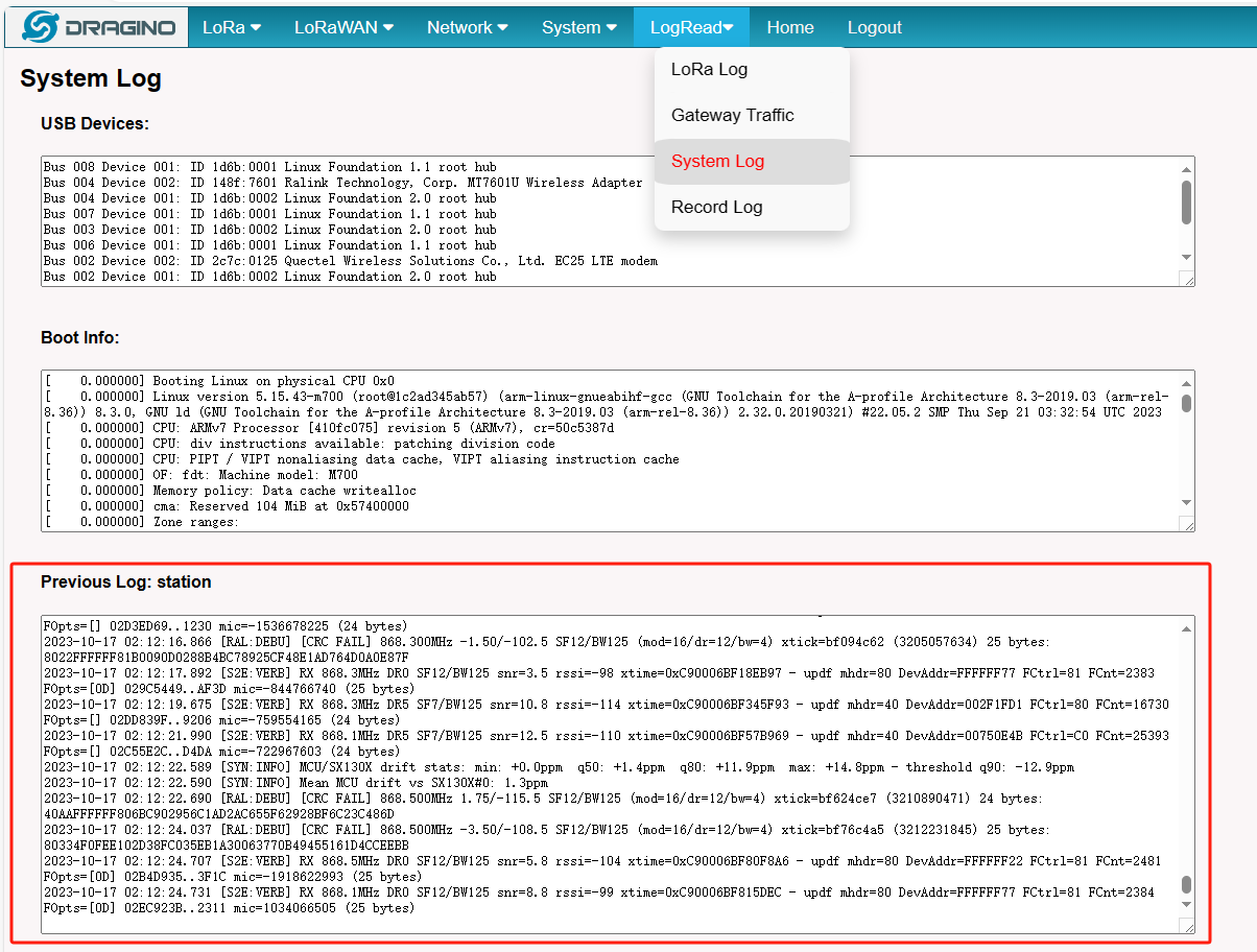
Station Log:
When the gateway starts Basic Station, users can check the logs of the station in the LogRead --> System Log interface
10.2 4G Log
User needs to access the Linux console of the gateway and enter the following command:
cat /var/log/qmilog.txt
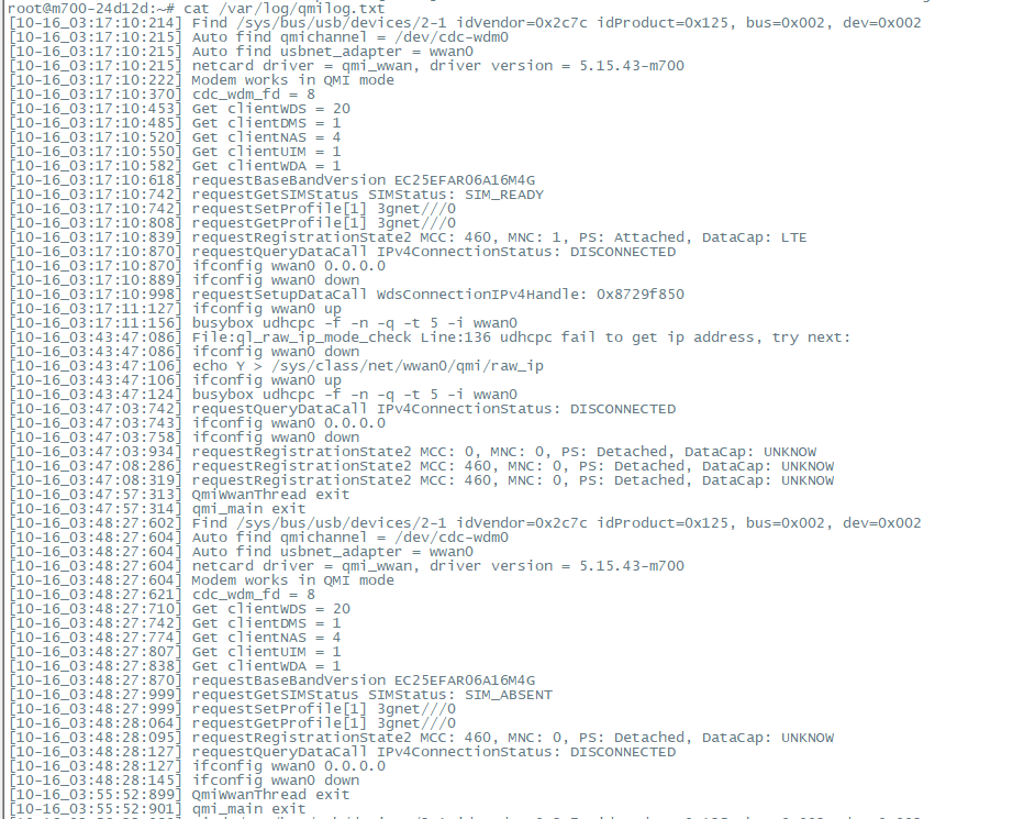
LPS8v2 use quectel-CM linux drive for dial up. The manual of this driver can be found here: quectel-CM driver user manual.
Below are some commands as reference:
Usage: /usr/bin/quectel-CM [options] -s [apn [user password auth]] Set apn/user/password/auth get from your network provider. auth: 1
pap, 2chap -p pincode Verify sim card pin if sim card is locked -p [quectel-][qmi|mbim]-proxy Request to use proxy -f logfilename Save log message of this program to file -u usbmonlog filename Save usbmon log to file -i interface Specify which network interface to setup data call when multi-modems exits -4 Setup IPv4 data call (default) -6 Setup IPv6 data call -k pdn Specify which pdn to hangup data call (by send SIGINT to 'quectel-CM -n pdn') -m iface-idx Bind QMI data call to wwan0_<iface idx> when QMAP used. E.g '-n 7 -m 1' bind pdn-7 data call to wwan0_1 -b Enable network interface bridge function (default 0) -v Verbose log mode, for debug purpose.[Examples] Example 1: /usr/bin/quectel-CM Example 2: /usr/bin/quectel-CM -s 3gnet Example 3: /usr/bin/quectel-CM -s 3gnet -v
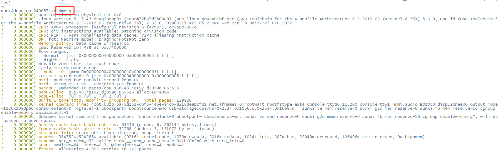
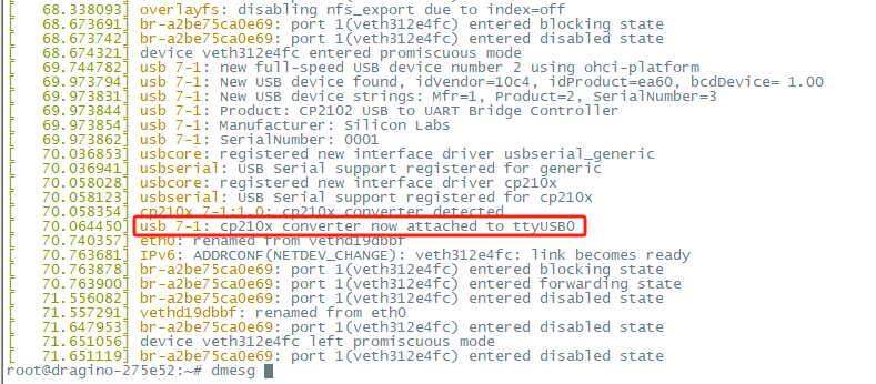
10.3 Dmesg Log
Users can check the logs of the Dmesg in the LogRead --> System Log interface:
10.4 Record Log
Users can record DMESG logs and LoRaWAN logs on the LogRead -->Record Log interface
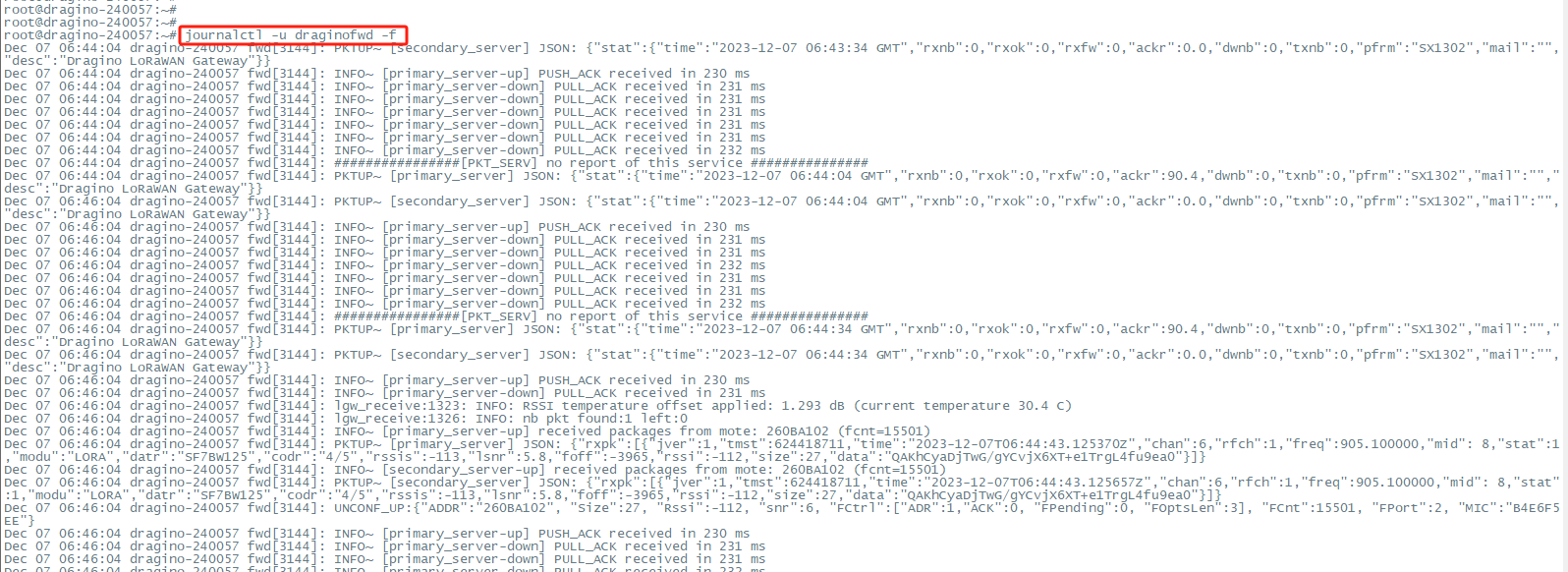
9.5 View gateway logs via Linux Command
Semtech UDP Log : journalctl -u draginofwd -f
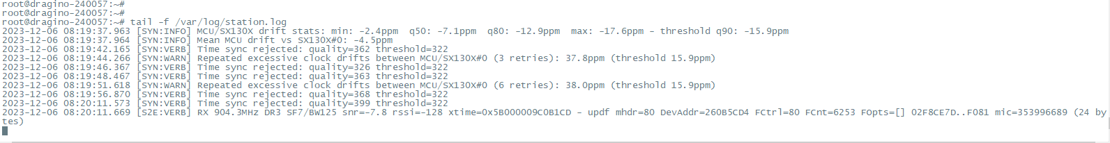
**Station Log: tail -f /var/log/station.log **
Dmesg Log: dmesg
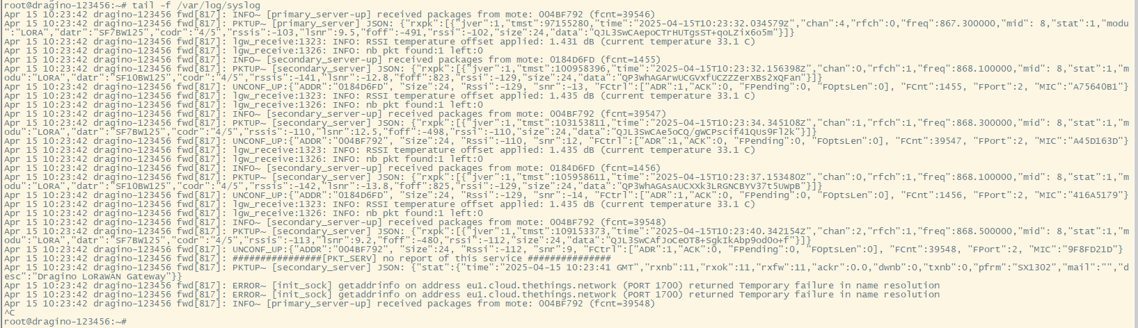
**SysLog : tail -f /var/log/syslog **
11. More Services
11.1 NTP Service/Time Synchronization
The gateway time sync service is provided by chrony service
1). Modify the NTP server address:
Configuration file path: /etc/chrony/chrony.conf
2). Start/Stop/Enable/Disable NTP service:
systemctl start chrony
systemctl stop chrony
systemctl disable chrony
systemctl enable chrony
12. More features
12.1 Chirpstack MQTT Forwarder
ChirpStack MQTT Forwarder is a MQTT packet forwarder for LoRa gateways. By default it forwards packets in Protobuf binary format, optionally it can be configured to use JSON encoding for debugging. In contrast to the ChirpStack Gateway Bridge, this component must always be installed on the gateway.
12.1.1 Configure Packet Forwarder
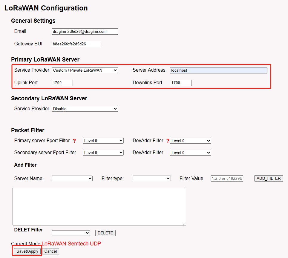
In the Dragino web-interface, you must configure the Packet Forwarder such that it forwards to localhost on port 1700.
By default, the web-interface can be accessed by entering the following URL in your browser: http://GATEWAY-IP-ADDRESS (replace GATEWAY-IP-ADDRESS by the actual IP address of your gateway). The default credentials are root / dragino.
- In the LoRaWAN menu, click LoRaWAN -- Semtech UDP
- Configure the following settings:
- Service Provider: Custom / Private LoRaWAN
- Server Address: localhost
- Uplink Port: 1700
- Downlink Port: 1700
- Click Save & Apply
12.1.2 Install ChirpStack MQTT Forwarder
SSH login
First you must login into the gateway using SSH:
ssh root@GATEWAY-IP-ADDRESS
The default password is: dragino.
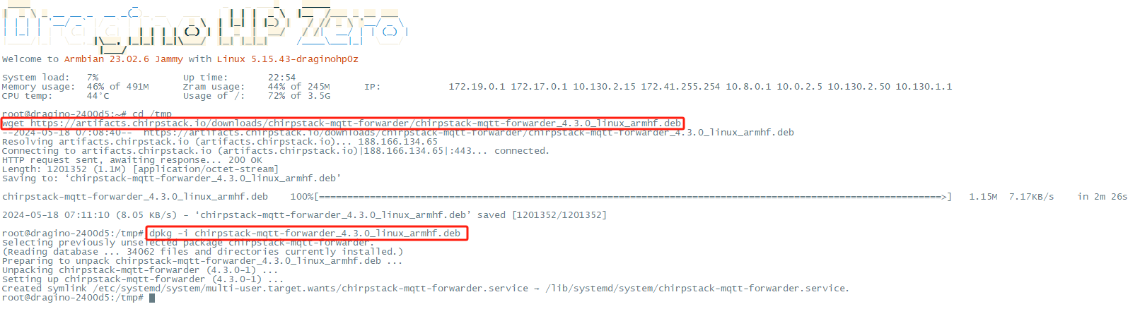
Download package
Use the following commands to download the latest version of the ChirpStack MQTT Forwarder package:
cd /tmp wget https://artifacts.chirpstack.io/downloads/chirpstack-mqtt-forwarder/chirpstack-mqtt-forwarder_4.3.0_linux_armhf.deb
**Install **
Use the dpkg package-manager to install the downloaded package. Example:
dpkg -i chirpstack-mqtt-forwarder_4.3.0_linux_armhf.deb
Configuration
To connect the ChirpStack MQTT Forwarder to your MQTT broker, you must update the ChirpStack MQTT Forwarder configuration file.
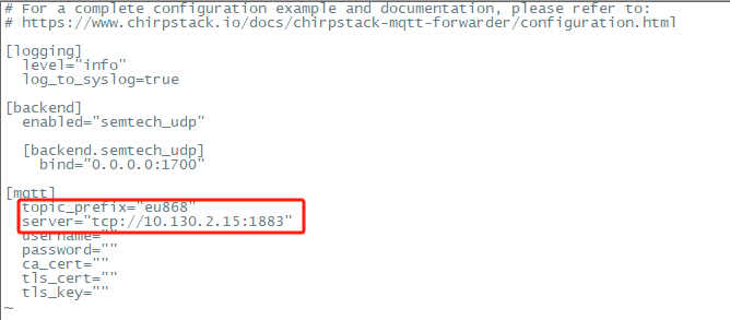
This file is located at: /etc/chirpstack-mqtt-forwarder/chirpstack-mqtt-forwarder.toml ChirpStack MQTT Forwarder Setting:
topic_prefix --> This corresponds to the frequency of the ChirpStack server
server --> Fill in the ChirpStack server address, Example: tcp://10.130.2.15:1883
username,password,ca_cert,tls_cert,tls_key parameters should be set as required.
Use commands to modify configuration files:
vim /etc/chirpstack-mqtt-forwarder/chirpstack-mqtt-forwarder.toml
(Re)start and stop commands
Use the following commands to (re)start and stop the ChirpStack MQTT Forwarder service:
# start
systemctl start chirpstack-mqtt-forwarder
# stop
systemctl stop chirpstack-mqtt-forwarder
# restart
systemctl restart chirpstack-mqtt-forwarder
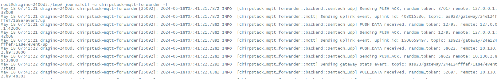
Note: If the LPS8v2 built-in server is running, it will cause a port conflict Check result
Use "** journalctl -u chirpstack-mqtt-forwarder -f **" to check the operation of ChirpStack MQTT Forwarder.
12.2 As a Data-only hotspot connect the helium blockchain
apt update && apt install helium-gateway
12.3 How does LPS8v2 filter unwanted lorawan packets
This feature is to filter the unwanted LoRaWAN packets. Purpose is to save the upstream traffic especially for a 4G cellular connection.
Please refer to the link below for specific usage:Filter unwanted LoRaWAN packets
12.4 How to modify the IP address of Docker bridge gateway
In the System--> System General page of the gateway, the ip address of the Docker bridge Gateway can be modified
Note that the docker bridge gateway should not conflict with the ip address of the gateway

12.5 Bridge LoRaWAN network to Modbus network
By following the steps below in the configuration example, Users can convert the uplink data of the lorawan sensor to modbus TCP data
LPS8v2 eliminates the need to add additional lorawan gateways to implement LoRaWAN to Modbus TCP
Step 1: Configure the LoRa Radio to your area Frequency Plan
The Frequency Plan has to be set the same as the Sensor node Frequency Plan.
Step 2: Copy the unique Gateway EUI & Configure the LoRaWAN Server address
Users need to connect the LPS8v2 configuration to the built-in lorawan server.
Every LPS8v2 has a unique gateway EUI. The ID can be found on the LoRaWAN Semtech page:
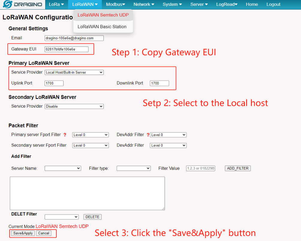
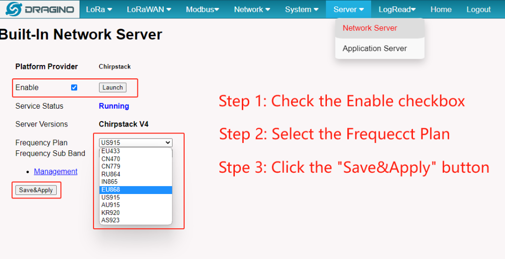
Step 3: Enable the Built-in LoRaWAN Network Server
Step 4: Logging to the Built-in LoRaWAN Network Server
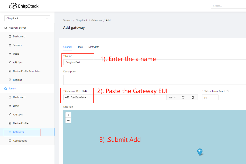
Step 5: Register the gateway to the built-in ChirpStack
Copy Gateway EUI from the previous step to the following interface:
Step 6: Register the Sensor-node to the built-in ChirpStack
The LPS8v2 gateway is already set up to connect to the built-in ChirpStack network, so we now need to configure the sensor device to connect to the built-in ChirpStack.
First we need to add the Device Profiles and Application (ignore them if they are already done).
1) Add Device Profiles
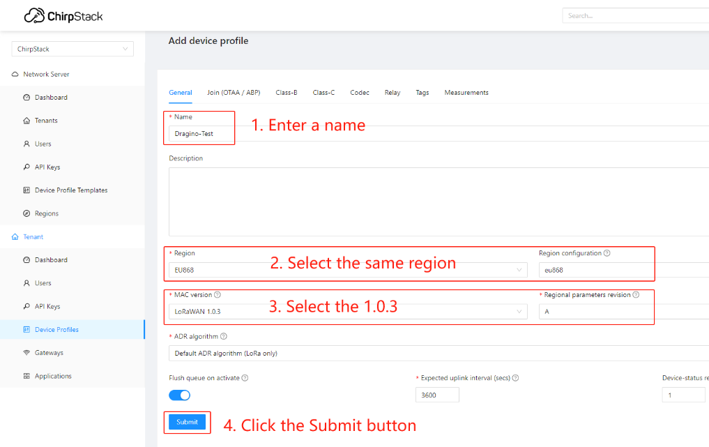
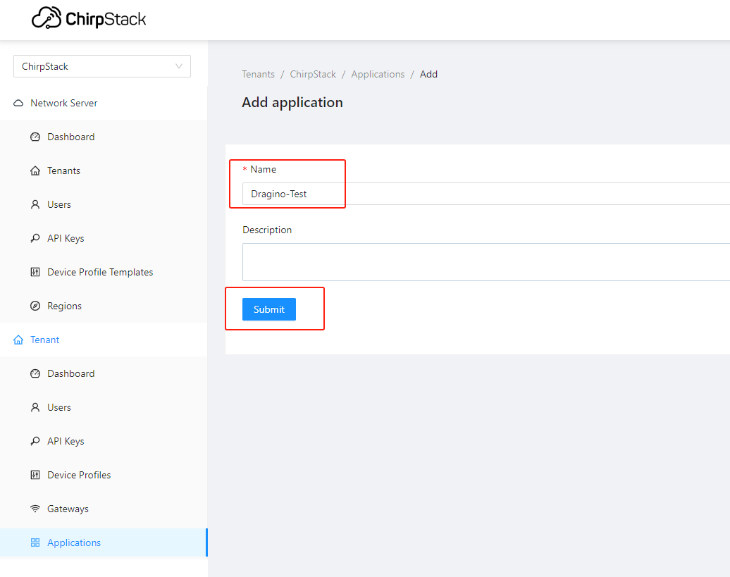
2) Add End Node Device Create an Application
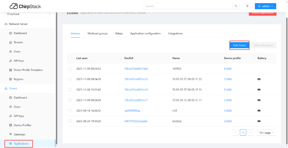
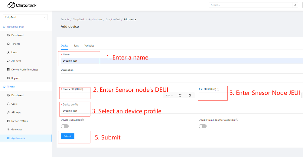
Add a device for the sensor node
Enter Device EUI, Join EUI(APP EUI)and APPKEY of the node Device, and select the Device profile added in the previous step
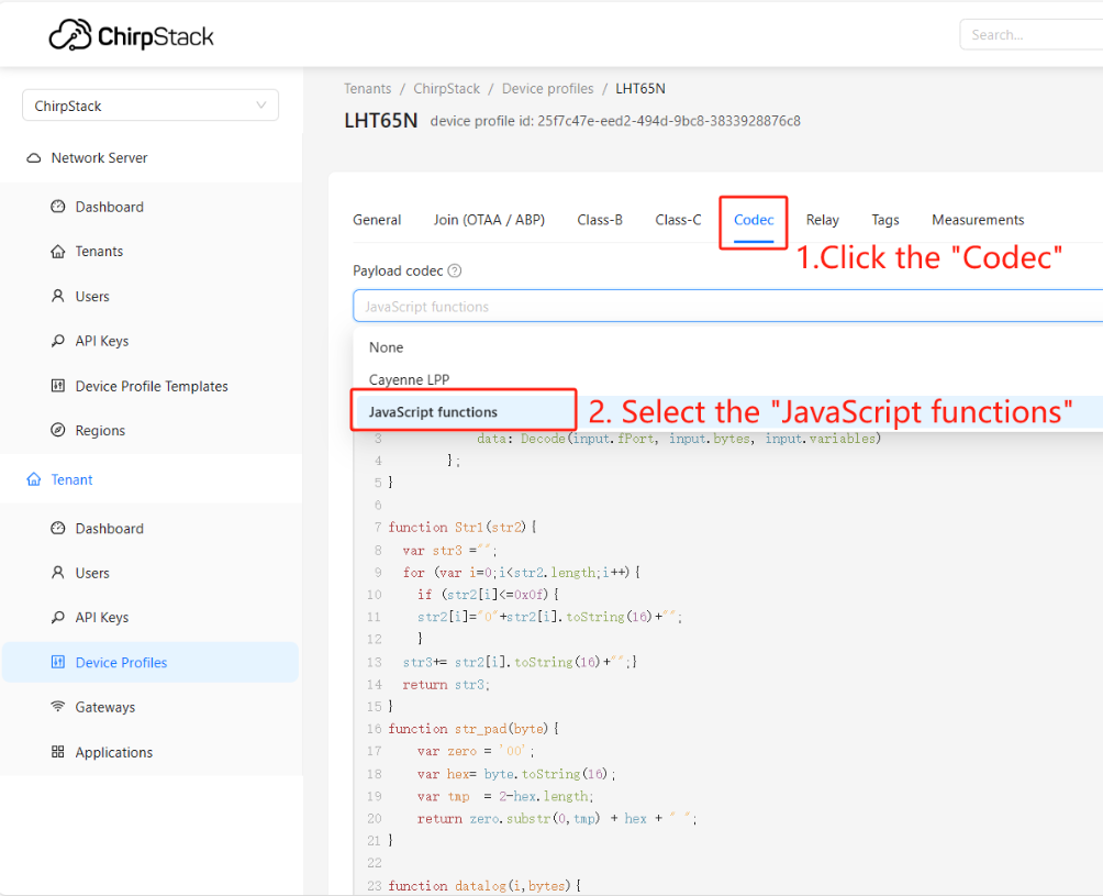
Step 7: Configure Sensor decode to Built-in Chirpstack
1) Add Sensor's decode to Chirpstack
Users can find the ChirpStack v4 decoder code for the Dragino End node in this link:
https://github.com/dragino/dragino-end-node-decoder
If the user's sensor is from another manufacturer, you need to search for the chirpstack decoder of the corresponding sensor on the official website of the corresponding manufacturer.
The following example is to add the LHT65N decoder:
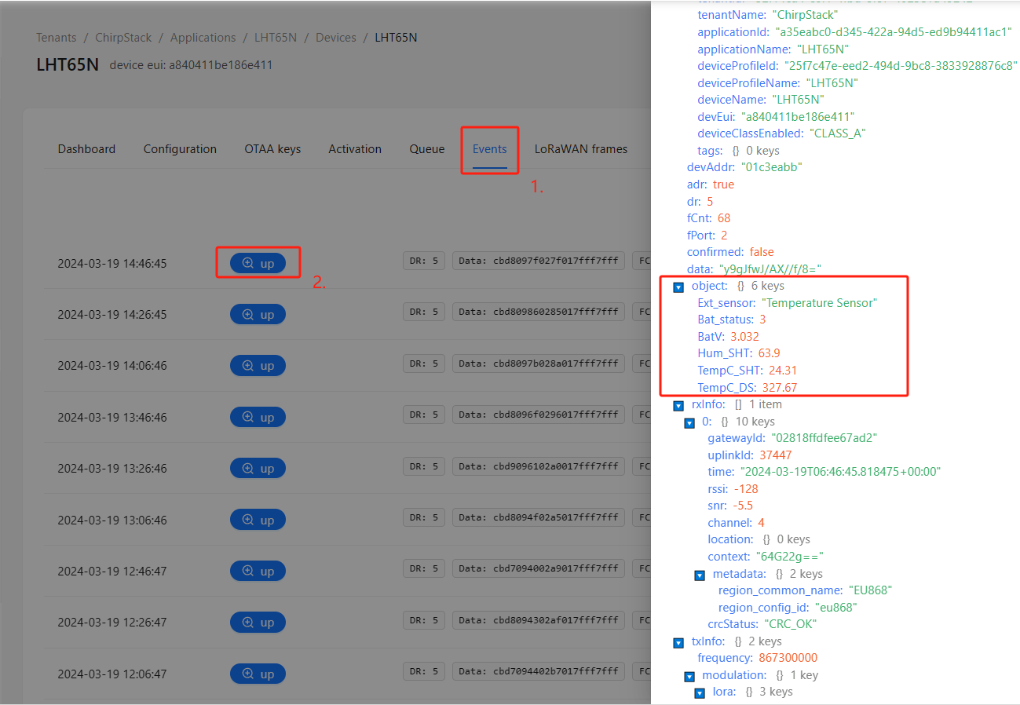
2) Check the decode on ChiprStack
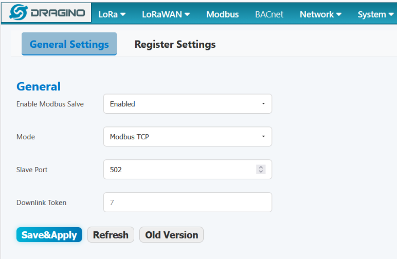
Step 8: Configure Modbus RTU/TCP Slave
The gateway can as a Modbus RTU/TCP slave to run, the user can set a range of the register to write a sensor node uplink data.
Modbus TCP General Settings
| Parameter | Description |
|---|---|
| Enable Modbus Slave | Enable the Modbus slave function. |
| Mode | Select the operating mode: RTU or TCP. |
| Slave Port | Set the TCP port for Modbus communication (e.g., 502). |
| Downlink Token | Enter the API key from the built-in ChirpStack server. Required if downlink functionality is needed. |
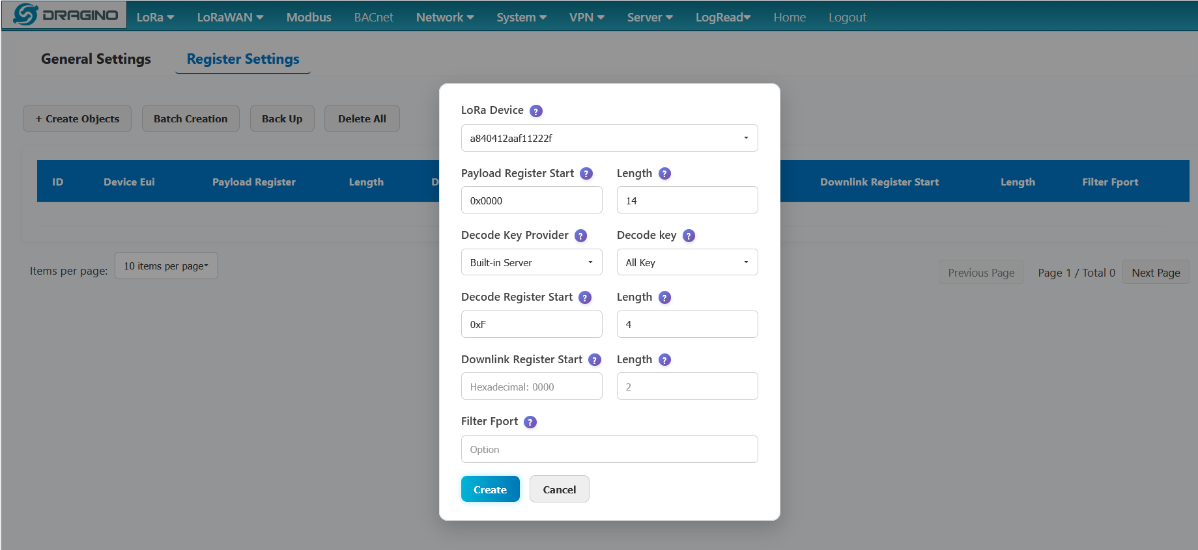
Example Configuration
Assume a sensor node with EUI a840412aaf11222f. If you set the Payload Register Start to 0xABCD and Payload Register Length to 14, the uplink data from this node will be written to registers starting at 0xABCD and occupying up to 14 registers. For instance, if the start address is 0x0000 and length is 14, the data occupies registers 0x0000 to 0x000D.
Note: Since the length of the payload is the same for different sensor nodes if The length of the data is greater than the configuration length, the data will be replaced with FFFF.
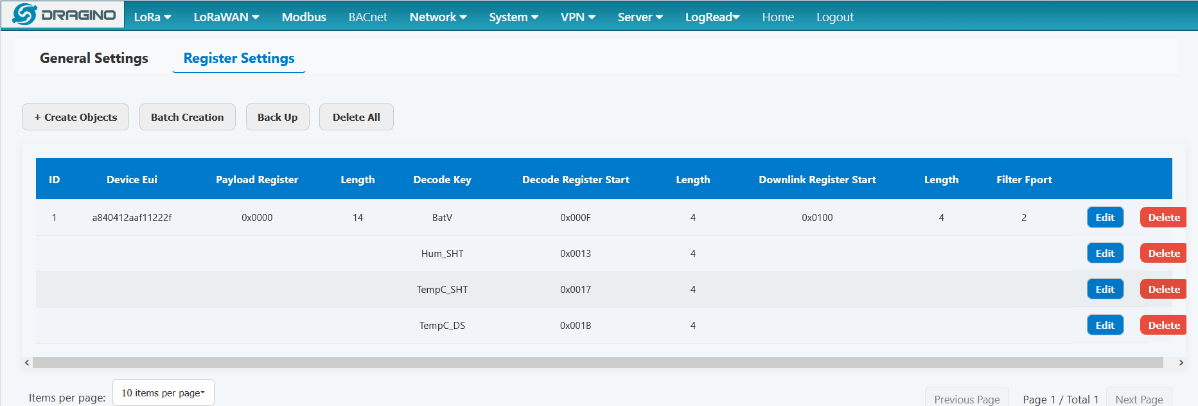
Create Objects: LoRa Device:
Select the LoRa device to configure.
- The device list automatically fetches devices that have joined the network from the built-in server
- Ensure that the device is properly connected and registered to the Built-in Server
- Device EUI is a unique identifier in 16-bit hexadecimal format
Payload Register Start:
pecify the number of registers to read.
- Value range: 1 - 65535
- Typically set to 16 (standard LoRa packet length)
- Adjust according to the actual data length of the device
Payload Register Length:
Select the key name to decode:
- All Key: automatically creates all available key names
- Specification: only the specified key name (e.g. temperature, humidity, etc.)
Select "All Key" to create all available key names at once
Decode Key Provider :
Select how the decoding key(name) is sourced:
The Key name needs to be the same as the decoder's.
- Built-in Server: Use the server's built-in decoder key name
- Maker: Use the standard configuration provided by the device manufacturer
- Custom: Customize the decoding key name
It is recommended to prioritize the use of Built-in Server for the best compatibility.
Decode Register Start :
Set the starting Modbus register address for storing decoded data.
- Use hexadecimal format
- The address should be separate from the Payload Register
- Each decoding type occupies consecutive register addresses
- It is recommended to set sufficient address spacing
Decode Register Length:
Specify the number of registers occupied by the decoded data.
- Default value: 4 registers
- Adjust according to the data type (usually 2 for integers, 4 for floating-point numbers and negative numbers)
- Floating-point and negative numbers are encoded using the IEEE754 standard.
- Ensure sufficient space to store the complete data
Downlink Register Start:
Set the starting address of the downlink control registers.
- Used to send control commands to LoRa devices
- Can be left blank if downlink control is not required
- The address should be separate from other registers
- Usually placed in the high-address region of the address space
Downlink Register Length:
Specify the number of registers for downlink data.
- Usually set to 2-4 registers
- Adjust according to the complexity of control commands
- Can be left blank if the downlink function is not used
Filter Fport:
Set the LoRaWAN port filter.
- Process only data packets from the specified port
- Port range: 1-255
- Leave blank to process data from all ports
- Helps distinguish different types of data packets
Note: Only 1 sensor can be written in the range set by the registers
About how long the register needs to be configured: In most cases, the payload length of Dragino's sensor is 11 bytes, which corresponds to a register length of 6. The modbus data forwarded by the gateway will have the Dev Address, Fcnt, Rssi, Payload, and Date of the sensor. Dev Address occupies 2, Fcnt occupies 1, Rssi occupies 1, Date occupies 2, so by default you need to configure the register length to be greater than or for 12.
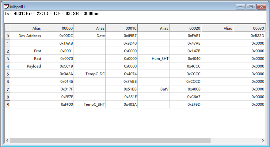
PLC(Modbus server/master) data show: Note: When the decoded data is a floating point number or a negative number, it will be encoded using IEEE754
For example: 23.20(real data) ---> 4037333333333333 [HEX](register show).
For example: -23.20(real data) --->C037333333333333 [HEX] (register show).
For example: 23(real data)-->4037000000000000 [HEX](register show).
13. FAQ
13.1 How to change Hostname
By default, Hostname is dragino-xxxxxx,If the user needs to change the hostname, the user needs to access the linux console of LPS8v2 and enter the following command:
hostnamectl set-hostname dragino-123456
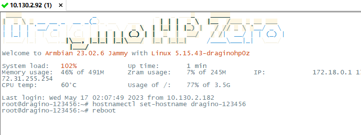
After the configuration is complete, run "reboot" to restart the gateway.
13.2 Build-in The Things Network migrate to ChirpStack
Migrate guide:
To stabilize the completion of the migration, The users can migrate in one of the following ways
Method 1. Using the Linux shell, Method 2. Flash a new image with the Chirpstack
Method 1: Using the Linux shell
wget -P /tmp http://repo.dragino.com/release/tool/chirpstack/migrate_chirpstack && chmod +x /tmp/migrate_chirpstack && /tmp/migrate_chirpstack
Method 2: Flash a new image
Image flash steps:** How to flash a new image(OS) to the gateway(LPS8V2)**
13.3 How to reduce the 4g data consumed
1). The gateway will check the network via ping 1.1.1.1/8.8.8.8 which will consume a lot of data, you can set the interval time to reduce data consume.
2. Change the LoRa status package interval time: It does not affect the connection between the gateway and the server, just the status packet interval
3. Disable the auto-update:
13.4 How to change built-in LoRaWAN Server from ChirpStack v4 to TTN Stack v3.
By default, the LPS8v2's built-in server is ChirpStack v4,
If the user needs to change the built-in server from ChirpStack v4 to TTN Stack v3, the User needs to download the image and flash it to the LPS8v2 gateway:
Image flash steps: How to flash a new image(OS) to the gateway(LPS8V2)
13.5 How to check my USB port dev/tty after i plug in USB device.
When an external USB device is connected to LPS8v2, the user can access the Linux console of the LPS8v2 gateway and run the following command to check the USB port dev/tty:
dmesg
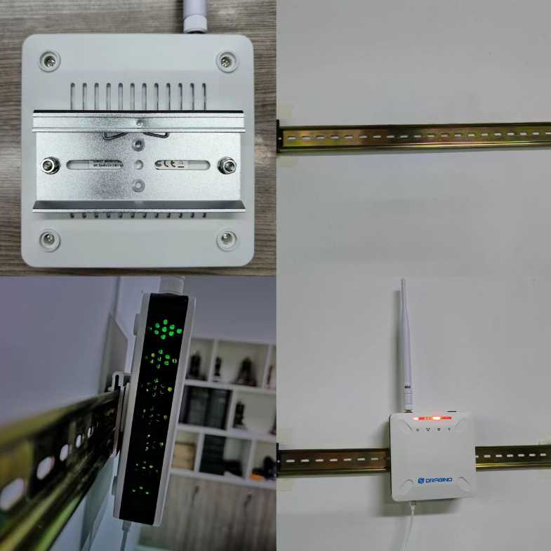
13.6 DIN Mount Reference:

14. Trouble Shooting
14.1 I can't log in to the built-in Server TTN Stack which shows 'Login failed'.
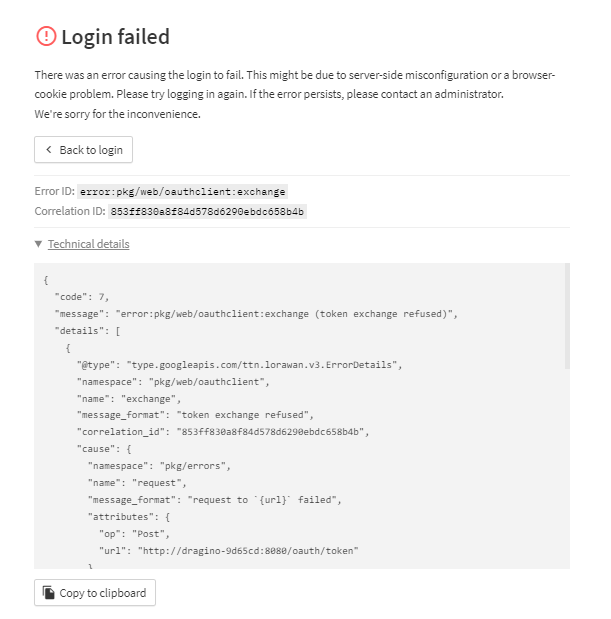
This is caused by the inconsistency between the built-in TTN-Stack domain configuration and your login URL.
By default, ttn-stack uses the gateway's domain name for URL resolution, but in some networks, they prefer to resolve IP-v4 addresses.
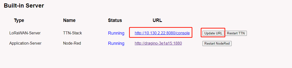
So you can change the domain name of the TTN-Stack configuration to the IPv4 address.
Click the update URL button to configure the URL with the current eth port address.
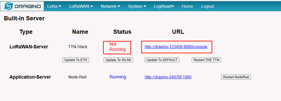
14.2 The built-in TTN status is "Not Running" and the URI is "dragino-123456". How users fix this problem
When this problem occurs, click "Update To DEFAULT" ,this problem will be fixed.
14.3 Fallback IP does not work, how can users check
When the computer has completed the above fallback IP configuration,the LPS8v2 Web UI is still not accessible via fallback IP.
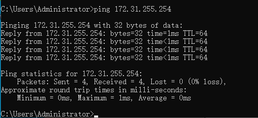
1. Check whether the configuration is correct
Run the CMD command to ipconfig and ping 172.31.255.254.
If this fails, the user needs to reconfigure.
2. Check whether the firewall is disabled
If the firewall is not down, this will affect access to the gateway.
14.4 Click "Manual_Update", why there is no response?
When you click "Manual_Update", the gateway will finish updating within 10 minutes and display the update log.
14.5 Why the LPS8V2's Access Point does not do not appear & Fallback IP unable to access
Note: The following steps are only applicable to Wi-Fi module MT7601U
Users can find the model of the wifi module on the LogRead-->System Log page:
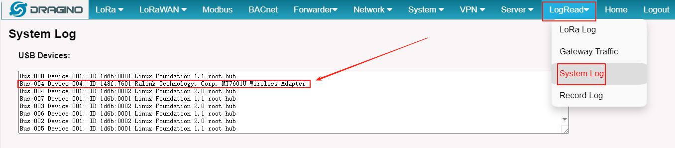
Earlier versions of the LPS8V2 which missing the AP driver and not installed the fallback package, so the users have to do an extra update.
apt update && apt install *dragino*
wget -P /tmp/ http://repo.dragino.com/release/hp0c-packages/linux-image-current-draginohp0z_22.05.2_armhf.deb && dpkg -i /tmp/linux-image-current-draginohp0z_22.05.2_armhf.deb
14.6 How to reset the built-in server
1) Build-in The Things Network
Refer to this link to delete the Built-in server's device.
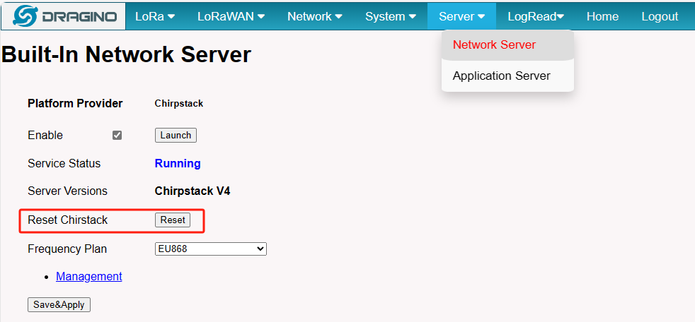
Delete devices from Build-in The Things Network 2) Build-in Chirpstack
Users need to click "Reset" on the Server-->NetServer interface, ChirpStack will be reset.
14.7 How to check the Storage of the gateway
Run the following command on the command line interface of the gateway to check the disk space usage:
df -h
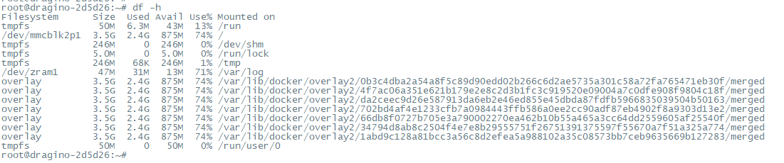
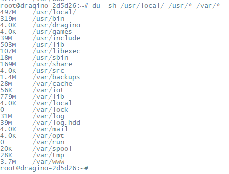
On the Linux console of the gateway, enter the following command to check the total disk space occupied by the files running on the gateway:
du -sh /usr/local/ /usr/* /var/*
14.8 How to clear the local server cache of the gateway using the command
Use the following commands to clear the local server cache:
#Stop the chirpstack service
systemctl stop chirpstack
#Stop the redis container
docker stop chirpstack_redis_1
#Remove the Redis container
docker-compose -f /usr/local/chirpstack/docker-compose.yml rm -f redis
#Remove the Redis data volume
docker volume rm chirpstack_redisdata
#start the chirpstack service
systemctl start chirpstack
14.9 How to Troubleshoot Login Issues
We recently released an update that upgraded the interface from HTTP to HTTPS and introduced the quick-configuration page.
However, there was a reset-related bug that could cause the web configuration page to load an outdated configuration file, which is why you encountered this issue.
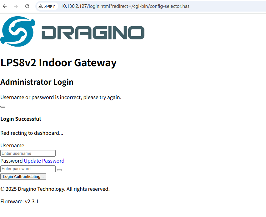
**Solution: **
1. Reboot the gateway which connects to the internet via eth ---> We have already pushed a new update that fixes this bug,The gateway will load the new updates upon restart.
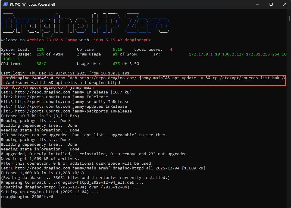
2. Manually update the gateway:
a). Connect the gateway AP
*** Wifi AP dragino-xxxxxx ***with password: dragino+dragino

b). Open the PowerShell(Windows) or Terminal(MAC)

c). Access the gateway via SSH
ssh `root@10.130.1.1`
passowrd: dragino

d). Update/Reinstall http package
echo "deb http://repo.dragino.com/ jammy main"&& apt update -y && cp /etc/apt/sources.list.bak /etc/apt/sources.list && apt reinstall dragino-httpd
15.10 Why does my gateway frequently crash/reboot?
Issue: Previous testing showed that excessive voltage levels could cause system crashes.
Solution: The kernel’s power management has been adjusted to ensure stable gateway operation.
Action:
- Upgrade the gateway’s DTB package to version 2026.02.02.
- Note: If your gateway can't receive this update, it may be due to a corrupted automatic update. In this case, repair the gateway’s automatic update functionality before proceeding.
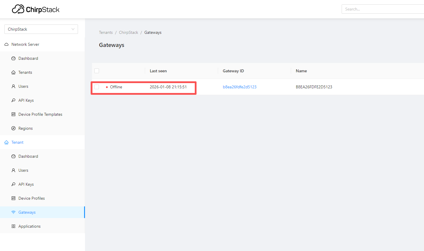
10. 11 Why is the gateway for my internal server displaying as offline?
Issue: On my gateway’s built-in server (ChirpStack), the gateway suddenly goes offline after a certain day/time. Even after reconfiguration or reboot, it does not come back online.
Cause: This issue is caused by a bug in a recent update.
Solution: Installing the latest update will resolve the problem.
Note: If your gateway cannot receive auto-updates, please follow the steps below to resolve the issue first.
15.12 Why is my gateway no longer fetching updates?
Issue: The update released on January 19 caused an incorrect update source address, preventing gateways from continuing to receive automatic updates.
Resolution: Follow the steps below to correct the update source address. After completing these steps, gateways will be able to resume automatic updates.
1. App Fix Method
Step 1. Download the APP:
https://repo.dragino.com/release/tool/autoupdate-fix-tool/Update%20Fix%20Tool.exe
Step 2. The Windows and the gateway are on the same network and open the APP
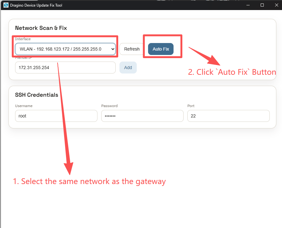
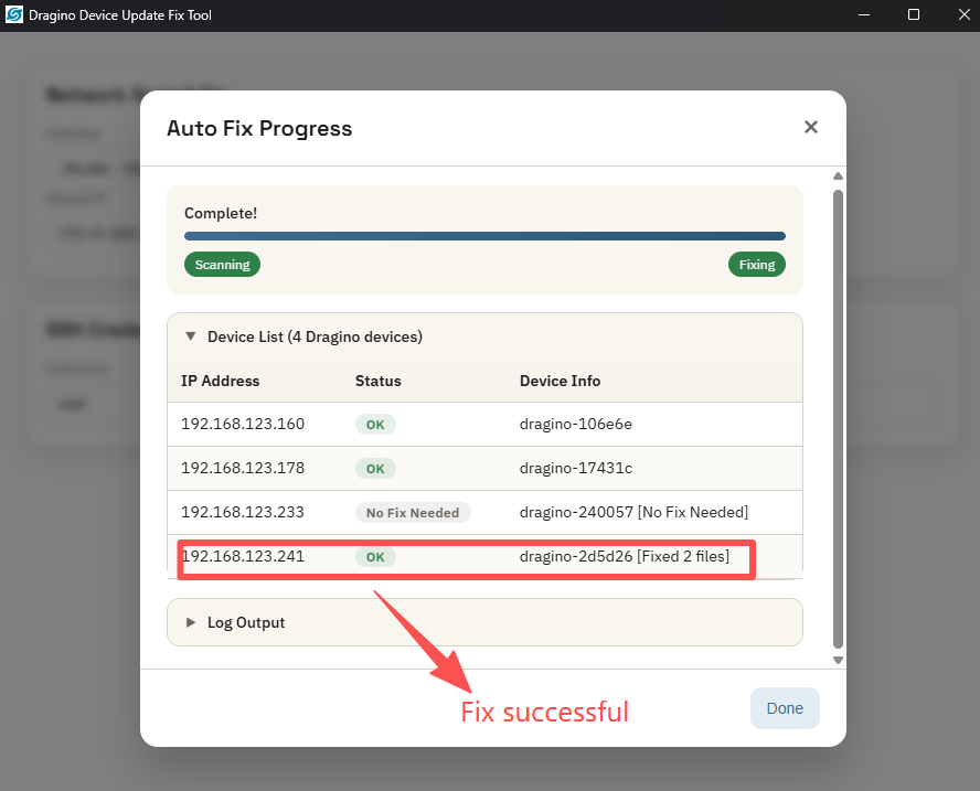
Step 3. Awaiting the fix outcome
2. Linux Command Line Fix Method
sed -i 's|deb http://repo.dragino.com/ dragino-ts main|deb http://repo.dragino.com/ jammy main|g' /etc/apt/sources.list.bak /etc/apt/sources.list
15. Supports
If you are experiencing issues and can't solve them, you can send mail to support@dragino.com.
With your question as detailed as possible. We will reply and help you in the shortest.
16. Reference
- Install Tago Core: Refer Install Tago Core in LPS8v2 in Instruction.
- Advance OS Reference Guide for LPS8v2.
17. Order Info
LPS8v2-XXX-YYY XXX: Frequency Band
-
AS923: LoRaWAN AS923 band
-
AU915: LoRaWAN AU915 band
-
EU868: LoRaWAN EU868 band
-
KR920: LoRaWAN KR920 band
-
US915: LoRaWAN US915 band
-
IN865: LoRaWAN IN865 band
YYY: 4G Cellular Option
-
EC25-E: EMEA, Korea, Thailand, India
-
EC25-AFX: America:Verizon, AT&T(FirstNet), U.S.Cellular; Canada:Telus
-
EC25-AUX: Latin America, New Zeland, Taiwan
-
EC25-J: Japan, DOCOMO, SoftBank, KDDI
More info about valid bands, please see EC25-E product page.
18. Manufacturer Info
Shenzhen Dragino Technology Development co. LTD
Room 202, Block B, BCT Incubation Bases (BaoChengTai), No.8 CaiYunRoad
LongCheng Street, LongGang District ; Shenzhen 518116,China
19. FCC Warning
This equipment has been tested and found to comply with the limits for a Class B digital device, pursuant to Part 15 of the FCC Rules. These limits are designed to provide reasonable protection against harmful interference in a residential installation. This equipment generates uses and can radiate radio frequency energy and, if not installed and used in accordance with the instructions, may cause harmful interference to radio communications. However, there is no guarantee that interference will not occur in a particular installation. If this equipment does cause harmful interference to radio or television reception, which can be determined by turning the equipment off and on, the user is encouraged to try to correct the interference by one or more of the following measures:
-- Reorient or relocate the receiving antenna.
-- Increase the separation between the equipment and receiver.
-- Connect the equipment into an outlet on a circuit different from that to which the receiver is connected.
-- Consult the dealer or an experienced radio/TV technician for help.
Changes or modifications not expressly approved by the party responsible for compliance could void the user's authority to operate the equipment.
The antenna(s) used for this transmitter must be installed to provide a separation distance of at least 20 cm from all persons and must not be co-located or operating in conjunction with any other antenna or transmitter.
1