WSC2-C
1. Introduction
1.1 Overview
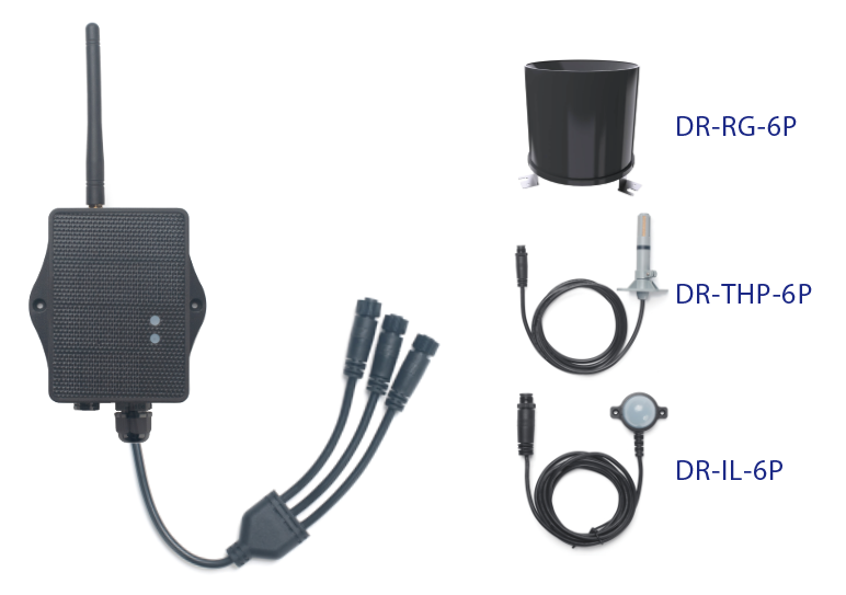
The WSC2-Compact-LS is Dragino's 3rd generation Weather Station Kit. It is designed for measuring atmospheric conditions to provide information for weather forecasts and to study the weather and climate.
The wireless transmitter (WSC2-Compact-LS) and the sensors of the 3rd generation weather station kit are low power and no need extra power supply or MQTT. It target the provide an easy installation method and low cost to provide a Long Range Wireless weather station kit.
The Weather Station Kit includes a LoRaWAN transmitter, a 3 in 1 sensor for temperature/humidity/air pressure , Illuminance sensor and rain guage.
The 3 in 1 sensor can measure below values: Temperature, Humidity, Air pressure. The transmitter use I2C interface to communicate with the weather station. It also has a pulse count input that can be used to connect a tipping bucket Rain Gauge.
1.2 Features & Spec for WSC2-Compact-LS Transmitter
- LoRaWAN 1.0.3 Class A
- Bands: CN470/EU433/KR920/US915/EU868/AS923/AU915/IN865
- Ultra-low power consumption
- Support interrupt rain gauge
- Support Bluetooth v5.1 and LoRaWAN remote configure
- Support wireless OTA update firmware
- AT Commands to change parameters
- Downlink to change configure
- IP66 Waterproof Enclosure
- 3000mAh Rechargeable Li-ion Battery
1.3 3 in 1 Sensor: DR-THP-6P
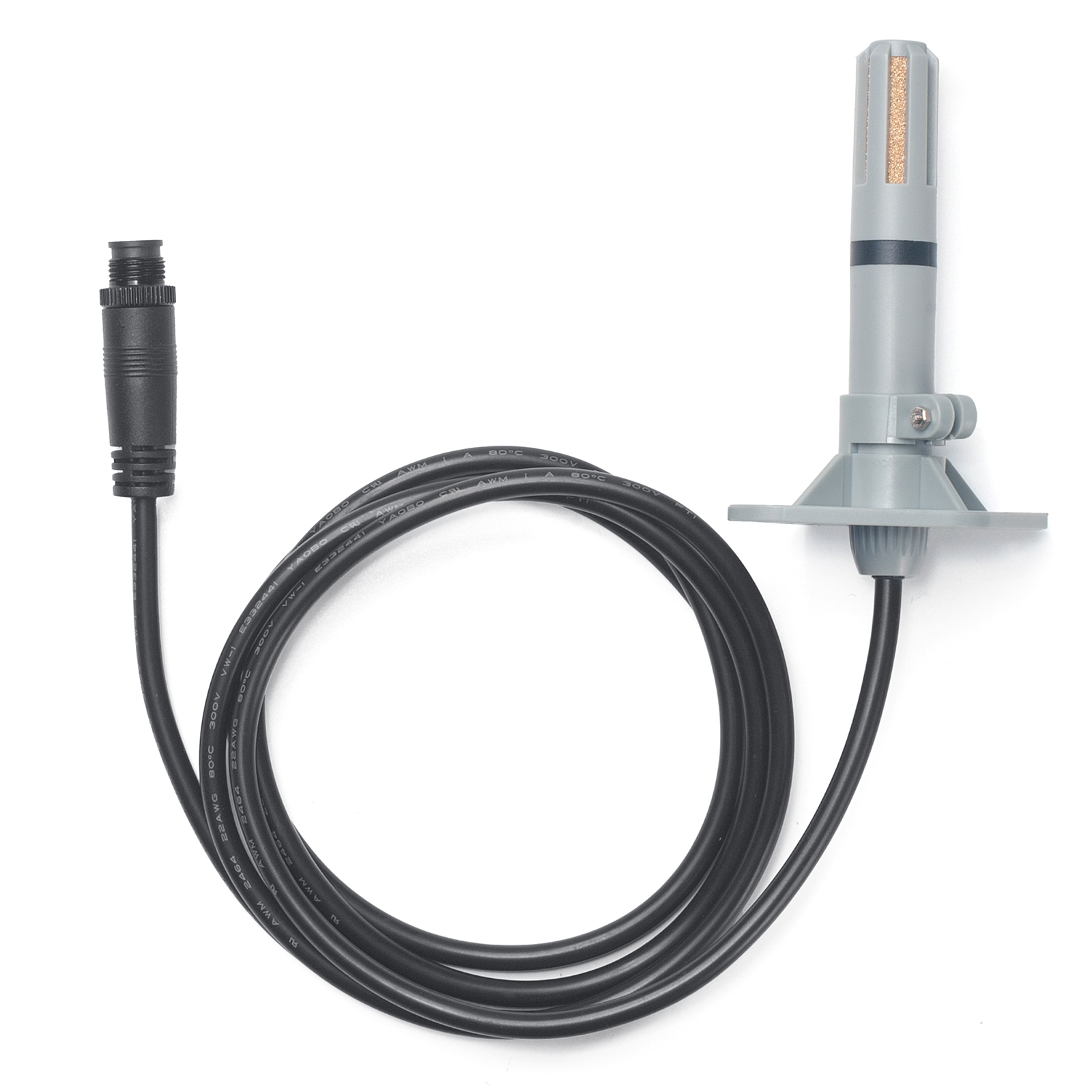
Temperature:
- Range: -40 to + 80°C
- Accuracy: ±0.2 @ 0-90 °C
- Resolution: 0.1°C
- Long Term Shift: <0.03 °C/yr
Humidity:
- Range: 0 ~ 99.9% RH
- Accuracy: ± 2%RH ( 0 ~ 100%RH)
- Resolution: 0.01% RH
- Long Term Shift: <0.25 %RH/yr
Air Pressure:
- Accuracy: ±0.1kPa@25°C 101kPa
- Range: 300 ~ 1100hPa
1.4 Illumination Sensor: DR-IL-6P
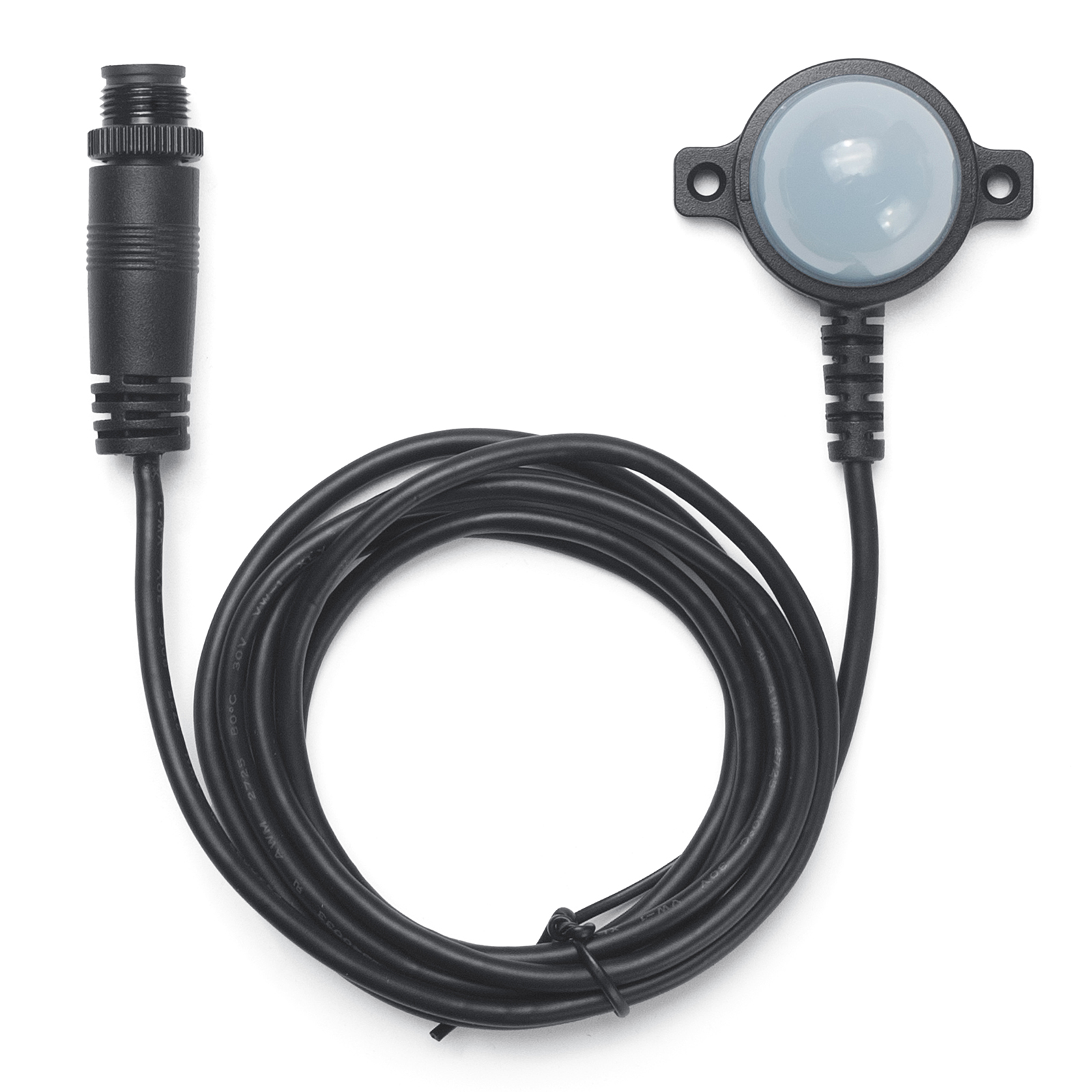
- Base on BH1750 Illumination Sensor
- Resolution: 1 lx
- Range: 0-65535 lx
- Operating Range: -40 °C ~ 85 °C
- Cable Length : 50cm
1.5 Rain Gauge: DR-RG-6P
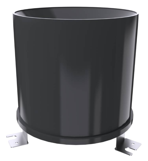
- Rain-bearing diameter: 200mm; sharp angle of blade: 40° ~ 45°
- Range: default 0~100mm/day
- Resolution: 0.1mm
- Rain intensity range: 0.01~4mm/min
- Output signal: pulse signal
- Cable speci cation: 2 meters 2 wire system (pulse signal)
1.6 Sleep mode and working mode
Deep Sleep Mode: Sensor doesn't have any LoRaWAN activate. This mode is used for storage and shipping to save battery life.
Working Mode: In this mode, Sensor will work as LoRaWAN Sensor to Join LoRaWAN network and send out sensor data to server. Between each sampling/tx/rx periodically, sensor will be in IDLE mode), in IDLE mode, sensor has the same power consumption as Deep Sleep mode.
1.7 Button & LEDs
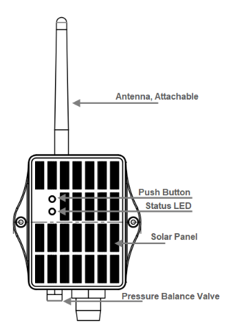
| Behavior on ACT | Function | Action |
|---|---|---|
| Send an uplink | If sensor is already Joined to LoRaWAN network, sensor will send an uplink packet, blue led will blink once. Meanwhile, BLE module will be active and user can connect via BLE to configure device. | |
| Active Device | Green led will fast blink 5 times, device will enter OTA mode for 3 seconds. And then start to JOIN LoRaWAN network. Green led will solidly turn on for 5 seconds after joined in network. Once sensor is active, BLE module will be active and user can connect via BLE to configure device, no matter if device join or not join LoRaWAN network. | |
| Deactivate Device | Red led will solid on for 5 seconds. Means device is in Deep Sleep Mode. |
1.8 BLE connection
WSC2-Compact-LS supports BLE remote configure.
BLE can be used to configure the parameter of sensor or see the console output from sensor. BLE will be only activate on below case:
- Press button to send an uplink
- Press button to active device.
- Device Power on or reset.
If there is no activity connection on BLE in 60 seconds, sensor will shut down BLE module to enter low power mode.
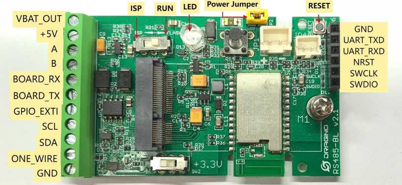
1.9 Pin Mapping
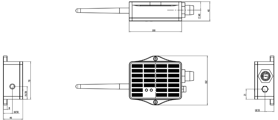
1.10 Mechanical (for LS version)
2. How to use
2.1 How it works?
Each WSC2-Compact-LS is shipped with a worldwide unique set of OTAA keys. To use WSC2-Compact-LS in a LoRaWAN network, user needs to input the OTAA keys in LoRaWAN network server. After finish installation as above. Create WSC2-Compact-LS in your LoRaWAN server and Power on WSC2-Compact-LS , it can join the LoRaWAN network and start to transmit sensor data. The default period for each uplink is 20 minutes.
2.2 Example to use for LoRaWAN network(OTAA)
This section shows an example for how to join the TTN V3 LoRaWAN IoT server. Usages with other LoRaWAN IoT servers are of similar procedure.
Assume the DLOS8N is already set to connect to TTN V3 network . We need to add the WSC2-Compact-LS device in TTN V3:
Step 1: Create a device in TTN V3 with the OTAA keys from WSC2-Compact-LS.
Each WSC2-Compact-LS is shipped with a sticker with the default device EUI as below:
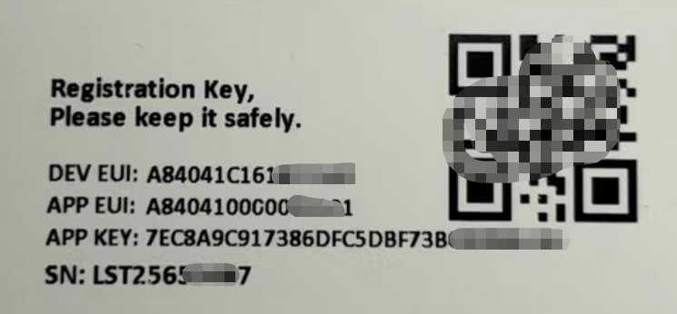
User can enter these keys in the LoRaWAN Server portal. Below is TTN V3 screen shot:
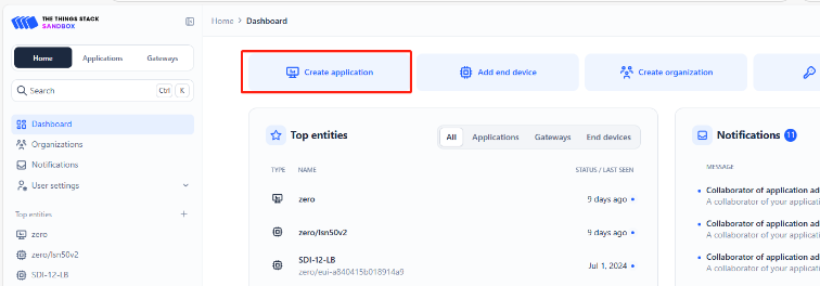
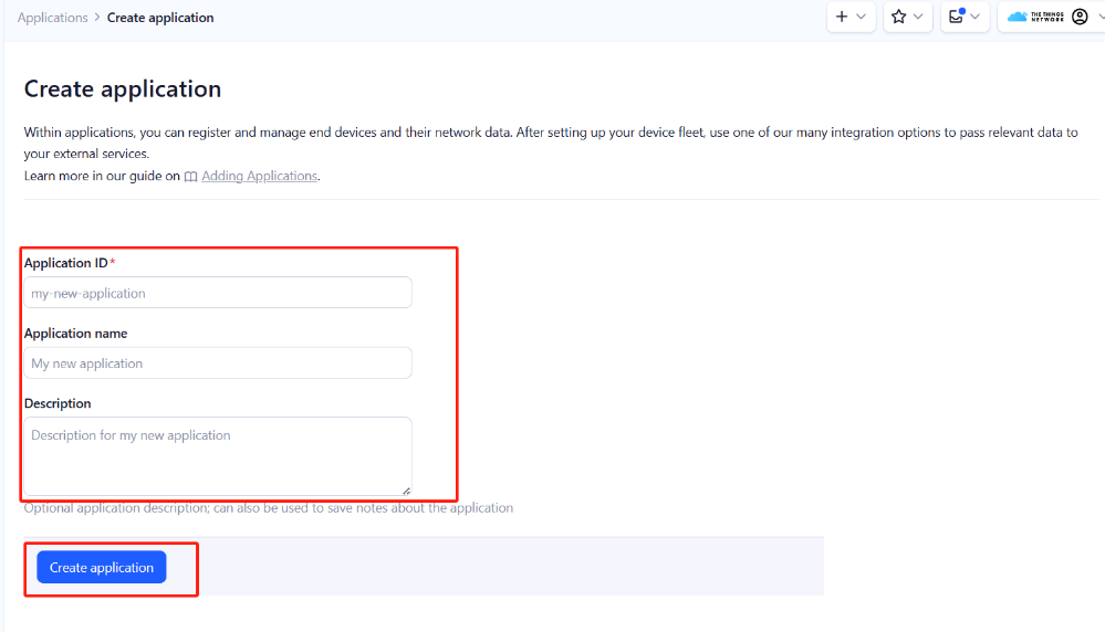
Create the application.
Add devices to the created Application.
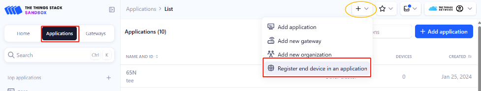
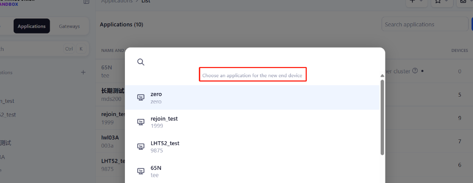
Enter end device specifics manually.
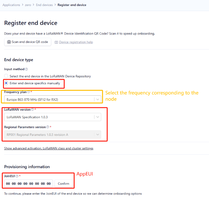
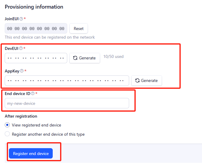
Add DevEUI and AppKey. Customize a platform ID for the device.
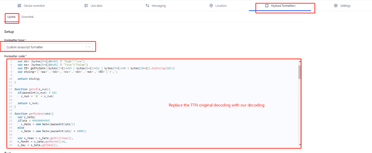
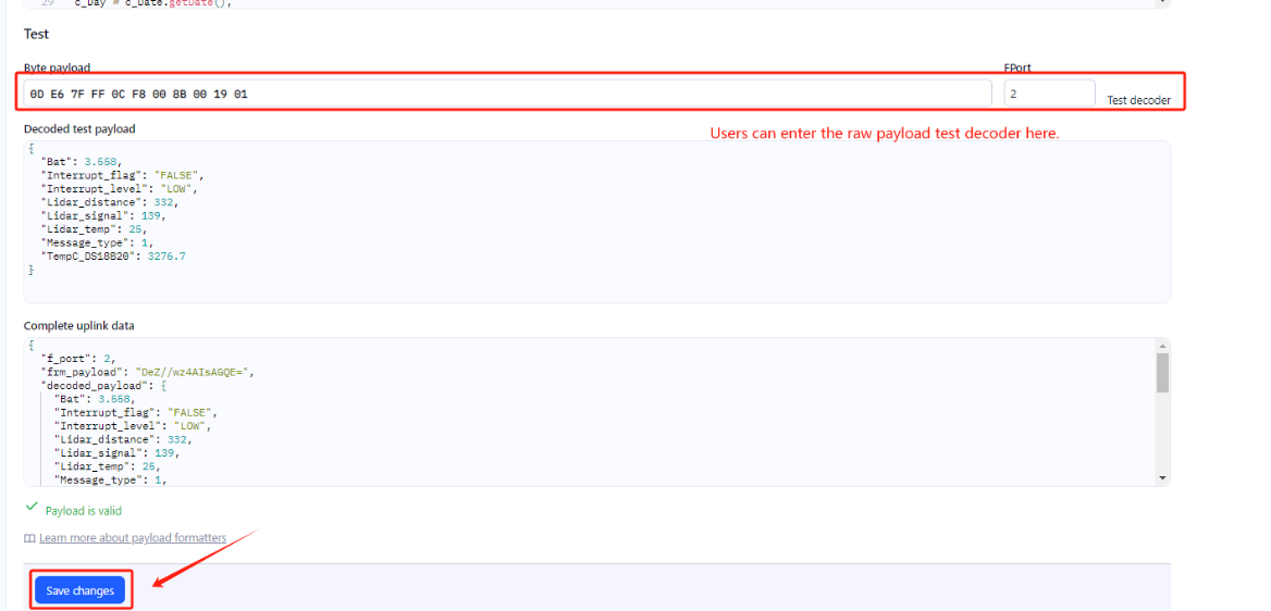
Step 2: Add decoder
In TTN, user can add a custom payload so it shows friendly reading.
Click this link to get the decoder: https://github.com/dragino/dragino-end-node-decoder/tree/main/
Below is TTN screen shot:
Step 3: Activate on WSC2-Compact-LS
Press the button for 5 seconds to activate the WSC2-Compact-LS.
Green led will fast blink 5 times, device will enter OTA mode for 3 seconds. And then start to JOIN LoRaWAN network.
Green led will solidly turn on for 5 seconds after joined in network.
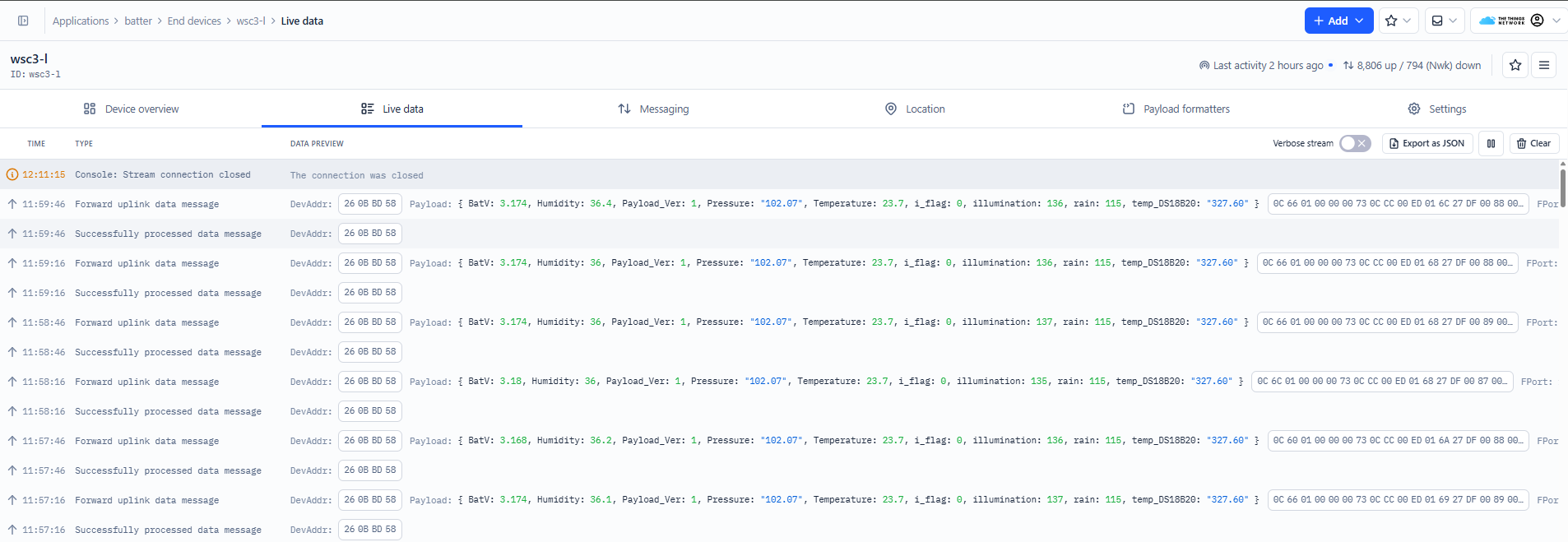
After join success, it will start to upload messages to TTN and you can see the messages in the panel.
2.3 Uplink Payload
Uplink payloads include two types: Valid Sensor Value and other status / control command.
- Valid Sensor Value: Use FPORT=2
- Other control command: Use FPORT other than 2.
2.3.1 Uplink FPORT=5, Device Status
Users can use the downlink command(0x26 01) to ask WSC2-Compact-LS to send device configure detail, include device configure status. WSC2-Compact-LS will uplink a payload via FPort=5 to server.
The Payload format is as below.
| Device Status(FPORT=5) | |||||
|---|---|---|---|---|---|
| Size(bytes) | 1 | 2 | 1 | 1 | 2 |
| Value | Sensor Model | Firmware Version | Frequency Band | Sub-band | BAT |
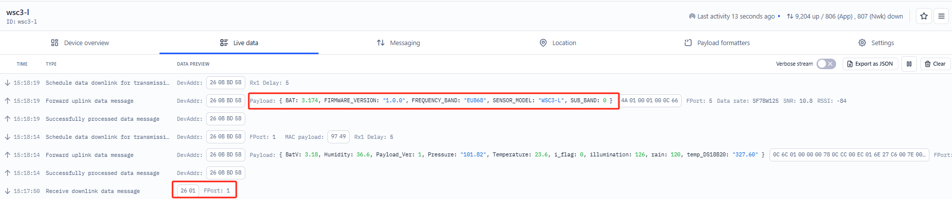
Sensor Model: For WSC2-Compact-LS, this value is 0x4A.
Firmware Version:0x0100, Means: v1.0.0 version.
Frequency Band:
0x01: EU868
0x02: US915
0x03: IN865
0x04: AU915
0x05: KZ865
0x06: RU864
0x07: AS923
0x08: AS923-1
0x09: AS923-2
0x0a: AS923-3
Sub-Band:
AU915 and US915:value 0x00 ~ 0x08
CN470: value 0x0B ~ 0x0C
Other Bands: Always 0x00
Battery Info:
shows the battery voltage for WSC2-Compact-LS MCU.
Ex1: 0x0C66/1000 = 3174/1000=3.174V
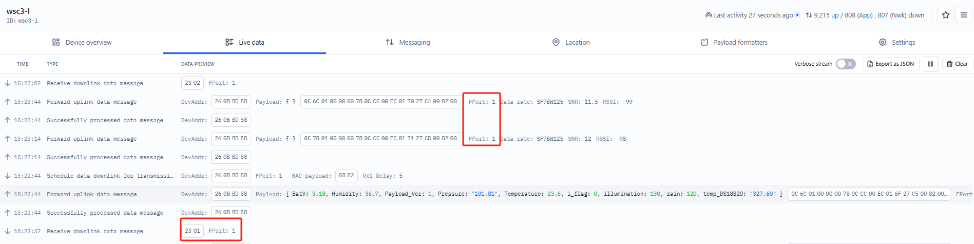
Users can also use the downlink command (0x23 01) to change the uplink port of WSC2-Compact-LS:
Example Downlink:0x23 01(Change to port 1)
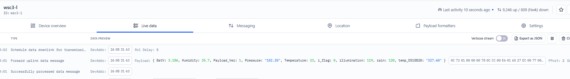
2.3.2 Uplink FPORT=2, Real time sensor value
WSC2-Compact-LS will send this uplink after Device Config uplink once join LoRaWAN network successfully. And it will periodically send this uplink. Default interval is 20 minutes and can be changed.
Uplink uses FPORT=2 and every 20 minutes send one uplink by default.
| Size(bytes) | 2 | 1 | 4 | 2 | 2 | 2 | 2 | 2 | 1 |
|---|---|---|---|---|---|---|---|---|---|
| Value | Battery | Payload_ver | Rain | temp_DS18B20 | Temperature | Humidity | Pressure | illumination | i_flag |
Battery
Sensor Battery Level.
Ex1: 0x0C72 = 3186mV
Ex2: 0x0B49 = 2889mV
Payload_ver
WSC2-Compact-LS can connect to different sensors. User can set the PAYVER_VER field to tell server how to decode the current payload.
Rain
Cumulative rainfall
Example:
0x00000078 = 120
DS18B20 Temperature sensor
This is an optional 2 bytes field. You can connect an external DS18B20 sensor to the +3.3V, 1-Wire, and GND pins. This field will then report the temperature.
Example:
-
If the payload is 0105H:
(0105H & FC00H == 0), therefore temp = 0105H / 10 = 26.1°C
-
If the payload is FF3FH:
(FF3FH & FC00H != 0), therefore temp = (FF3FH - 65536) / 10 = -19.3°C
Temperature
Example:
If payload is: 0105H: (0105 & 8000 == 0), temp = 0105H /10 = 26.1 degree
If payload is: FF3FH : (FF3F & 8000 == 1) , temp = (FF3FH - 65536)/10 = -19.3 degrees.
(FF3F & 8000:Judge whether the highest bit is 1, when the highest bit is 1, it is negative)
Humidity
Example:
0x(0199) = 409 Value: 409 / 10=40.9, So 40.9%
Pressure
Example:
0x(27ED) = 10221 Value: 10221/100 = 102.21Pa
illumination
Example:
0x(0097) = 151 Lux
i_flag
Ex1: 0x00>>5&0x01=0x00 : Normal uplink packet.
Ex2: 0x01>>5&0x01=0x01 : Interrupt Uplink Packet.
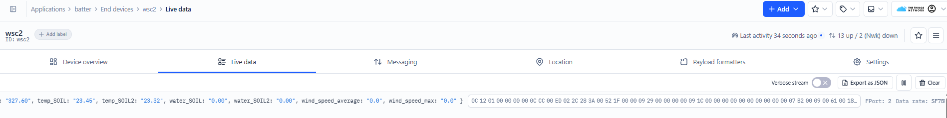
2.3.3 Uplink FPORT=2, Real time sensor value(Since version 1.0.6)
Starting from firmware version 1.0.6, the WSC2-Compact-LS adds support for:
- One wind speed sensor
- Two soil sensor
- One TSR (Total Solar Radiation) sensor
- One PAR (Photosynthetically Active Radiation) sensor
**Note on Soil Sensors: **The WSC2-Compact-LS can only recognize soil sensors with addresses 01 and 02. When using two soil sensors simultaneously, they must be configured with different addresses (one must be 01 and the other 02).
After enabling the corresponding sensor data readings using the AT+WSS command based on actual requirements, the device supports a new uplink format on FPORT=2 to report real-time values from these sensors.
**Configuration Commands & Wiring Method: **Refer to section 3.4.7 for detailed wiring instructions and command usage.
Example:
AT+WSS=1,1,1,1,1 enables all available sensors (default is AT+WSS=0,0,0,0,0).

Battery
Sensor Battery Level.
Ex1: 0x0C12 = 3090mV
Ex2: 0x0B49 = 2889mV
Payload_ver
WSC2-Compact-LS can connect to different sensors. User can set the PAYVER_VER field to tell server how to decode the current payload.
Rain
Cumulative rainfall
Example:
0x00000078 = 120
DS18B20 Temperature sensor
This is an optional 2 bytes field. You can connect an external DS18B20 sensor to the +3.3V, 1-Wire, and GND pins. This field will then report the temperature.
Example:
-
If the payload is 0105H:
(0105H & FC00H == 0), therefore temp = 0105H / 10 = 26.1°C
-
If the payload is FF3FH:
(FF3FH & FC00H != 0), therefore temp = (FF3FH - 65536) / 10 = -19.3°C
Temperature
Example:
If payload is: 0105H: (0105 & 8000 == 0), temp = 0105H /10 = 26.1 degree
If payload is: FF3FH : (FF3F & 8000 == 1) , temp = (FF3FH - 65536)/10 = -19.3 degrees.
(FF3F & 8000:Judge whether the highest bit is 1, when the highest bit is 1, it is negative)
Humidity
Example:
0x(0199) = 409 Value: 409 / 10=40.9, So 40.9%
Pressure
Example:
0x(27ED) = 10221 Value: 10221/100 = 102.21Pa
illumination
Example:
0x(0097) = 151 Lux
i_flag
Ex1: 0x00>>5&0x01=0x00 : Normal uplink packet.
Ex2: 0x01>>5&0x01=0x01 : Interrupt Uplink Packet.
(Address 1) water_SOIL
Get the moisture content of the soil. The value range of the register is 0-10000(Decimal), divide this value by 100 to get the percentage of moisture in the soil.
For example, if the data you get from the register is 0x05 0xDC, the moisture content in the soil is 05DC(H) = 1500(D) /100 = 15%.
(Address 1) conduct_SOIL
Get the temperature in the soil. The value range of the register is -4000 - +800(Decimal), divide this value by 100 to get the temperature in the soil. For example, if the data you get from the register is 0x09 0xEC, the temperature content in the soil is
Example:
If payload is 0105H: ((0x0105 & 0x8000)>>15 === 0),temp = 0105(H)/100 = 2.61 °C
If payload is FF7EH: ((FF7E & 0x8000)>>15 ===1),temp = (FF7E(H)-FFFF(H))/100 = -1.29 °C
(Address 1) temp_SOIL
Obtain soluble salt concentration in soil or soluble ion concentration in liquid fertilizer or planting medium. The value range of the register is 0 - 20000(Decimal)( Can be greater than 20000).
For example, if the data you get from the register is 0x00 0xC8, the soil conductivity is 00C8(H) = 200(D) = 200 uS/cm.
Generally, the EC value of irrigation water is less than 800uS / cm.
(Address 2) water_SOIL
Get the moisture content of the soil. The value range of the register is 0-10000(Decimal), divide this value by 100 to get the percentage of moisture in the soil.
For example, if the data you get from the register is 0x05 0xDC, the moisture content in the soil is 05DC(H) = 1500(D) /100 = 15%.
(Address 2) conduct_SOIL
Get the temperature in the soil. The value range of the register is -4000 - +800(Decimal), divide this value by 100 to get the temperature in the soil. For example, if the data you get from the register is 0x09 0xEC, the temperature content in the soil is
Example:
If payload is 0105H: ((0x0105 & 0x8000)>>15 == 0),temp = 0105(H)/100 = 2.61 °C
If payload is FF7EH: ((FF7E & 0x8000)>>15 ==1),temp = (FF7E(H)-FFFF(H))/100 = -1.29 °C
(Address 2) temp_SOIL
Obtain soluble salt concentration in soil or soluble ion concentration in liquid fertilizer or planting medium. The value range of the register is 0 - 20000(Decimal)( Can be greater than 20000).
For example, if the data you get from the register is 0x00 0xC8, the soil conductivity is 00C8(H) = 200(D) = 200 uS/cm.
Generally, the EC value of irrigation water is less than 800uS / cm.
wind_speed_max
If payload is 000FH: wind_speed_max= 000F(H)/10 = 1.5
wind_speed_average
If payload is 003DH: wind_speed_average= 003D(H)/10 = 6.1
WIND_SPEED
If payload is 0006H: WIND_SPEED= 0006(H)/10 = 0.6
WIND_LEVEL
If payload is 0001H: WIND_LEVEL= 0001(H) = 1
WIND_ANGLE
If payload is 07B1H: WIND_ANGLE= 07B1(H)/10 = 196.9
WIND_DIRECTION
If payload is 0009H: WIND_DIRECTION= 0009(H) = 9
TSR
If payload is 0061H: TSR= 0061(H) = 97
PAR
If payload is 0018H: TSR= 0018(H) = 24
2.4 Unix TimeStamp
WSC2-Compact-LS uses Unix TimeStamp format based on
Users can get this time from the link: https://www.epochconverter.com/
Below is the converter example
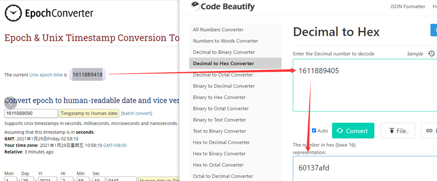
So, we can use AT+TIMESTAMP=1742278702 or downlink 3067D9102E to set current time : March 18, 2025 06:18:22
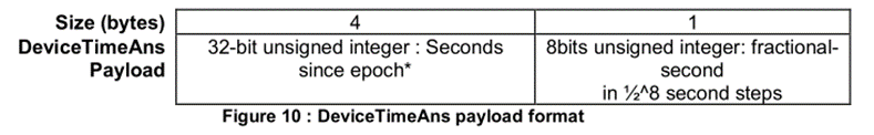
2.5 Set Device Time
There are two ways to set the device's time:
1. Through LoRaWAN MAC Command (Default settings)
Users need to set SYNCMOD=1 to enable sync time via the MAC command.
Once WSC2-Compact-LS Joined LoRaWAN network, it will send the MAC command (DeviceTimeReq) and server will reply with (DeviceTimeAns) to send the current time to WSC2-Compact-LS. If WSC2-Compact-LS fails to get the time from server, WSC2-Compact-LS will use the internal time and wait for next time request (AT+SYNCTDC to set time request period, default is 10 days).
Note: LoRaWAN Server needs to support LoRaWAN v1.0.3(MAC v1.0.3) or higher to support this MAC command feature, Chirpstack,TTN v3 and loriot support but TTN v2 doesn't support. If server doesn't support this command, it will through away uplink packet with this command, so user will lose the packet with time request for TTN v2 if SYNCMOD=1.
2. Manually Set Time
Users need to set SYNCMOD=0 to manual time, otherwise, the user set time will be overwritten by the time set by the server.
2.6 Frequency Plans
The WSC2-Compact-LS uses OTAA mode and below frequency plans by default. Each frequency band use different firmware, user update the firmware to the corresponding band for their country.
/docs/wiki/Configuration/end-node/frequency-band/
3. Configure WSC2-Compact-LS
3.1 Configure Methods
WSC2-Compact-LS supports below configure method:
-
AT Command via Bluetooth Connection (Recommended): BLE Configure Instruction.
-
AT Command via UART Connection : See UART Connection.
-
LoRaWAN Downlink. Instruction for different platforms: See IoT LoRaWAN Server section.
3.2 Serial Access Password
After the Bluetooth or UART connection is successful, use the Serial Access Password to enter the AT command window.
The label on the box of the node will print the initial password: AT+PIN=xxxxxx, and directly use the six-digit password to access the AT instruction window.
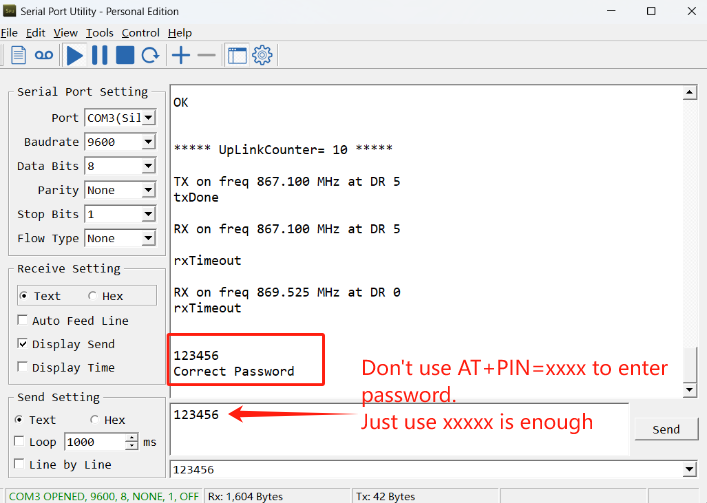
If you need to change the password, use AT+PWORD=xxxxxx (6 characters)
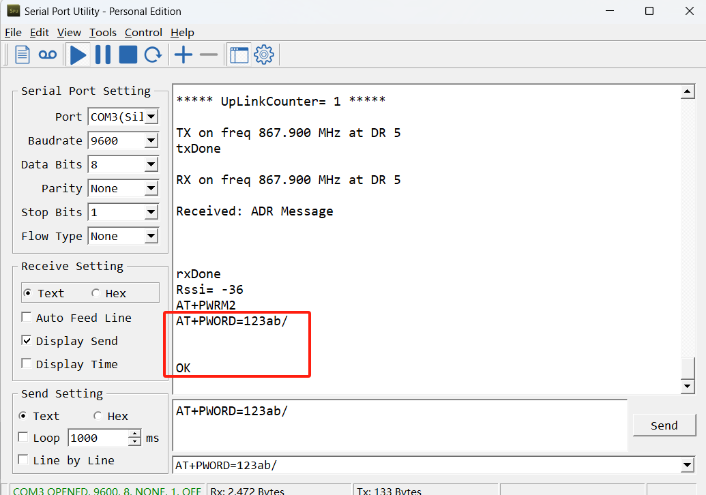
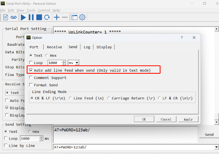
Note: After entering the command, you need to add a line break, and you can also set automatic line breaks in the Bluetooth tool or UART connection tool.
3.3 General Commands
These commands are to configure:
- General system settings like: uplink interval.
- LoRaWAN protocol & radio related command.
They are same for all Dragino Devices which support DLWS-005 LoRaWAN Stack. These commands can be found on the wiki:
/docs/wiki/Configuration/end-node/at-commands-downlink/
3.4 Commands special design for WSC2-Compact-LS
These commands only valid for WSC2-Compact-LS, as below:
3.4.1 Set Transmit Interval Time
Feature: Change LoRaWAN End Node Transmit Interval.
AT Command: AT+TDC
| Command Example | Function | Response |
|---|---|---|
| AT+TDC=? | Show current transmit Interval | 30000 OK the interval is 30000ms = 30s |
| AT+TDC=60000 | Set Transmit Interval | OK Set transmit interval to 60000ms = 60 seconds |
Downlink Command: 0x01
Format: Command Code (0x01) followed by 3 bytes time value.
If the downlink payload=0100003C, it means set the END Node's Transmit Interval to 0x00003C=60(S), while type code is 01.
- Example 1: Downlink Payload: 0100001E // Set Transmit Interval (TDC) = 30 seconds
- Example 2: Downlink Payload: 0100003C // Set Transmit Interval (TDC) = 60 seconds
3.4.2 Set Interrupt Mode
Feature, Set Interrupt mode for GPIO_EXIT of pin.
When AT+INTMOD=0 is set, GPIO_EXIT is used as a digital input port.
AT Command: AT+INTMOD
| Command Example | Function | Response |
|---|---|---|
| AT+INTMOD=? | Show current interrupt mode | 0 OK the mode is 0 =Disable Interrupt |
| AT+INTMOD=2 | Set Transmit Interval (Disable Interrupt), (Trigger by rising and falling edge) (Trigger by falling edge) (Trigger by rising edge) | OK |
Downlink Command: 0x06
Format: Command Code (0x06) followed by 3 bytes.
This means that the interrupt mode of the end node is set to 0x000003=3 (rising edge trigger), and the type code is 06.
- Example 1: Downlink Payload: 06000000 // Turn off interrupt mode
- Example 2: Downlink Payload: 06000003 // Set the interrupt mode to rising edge trigger
3.4.3 Set or get the total count value
Feature: The user can set the counting to start from the set value according to the requirements. (only available in counting mode).
AT Command:
| Command Example | Function | Response |
|---|---|---|
| AT+SETCNT=1000 | Set the total count to start from 1000 | OK |
Downlink Command:
Format: Command Code (0x09) followed by 4 bytes time value.
If the downlink payload=09000003E8, This means that the count of the END node will start counting from setting 0x000003E8=1000 (times). while type code is 09.
- Example 1: Downlink Payload: 09000003E8 // Set the value to start counting from 1000 = 1000 (times)
3.4.4 Set interrupt or counting mode
Feature: Users can set the trigger mode to counting mode or interrupt mode as needed.
AT Command:
| Command Example | Function | Response |
|---|---|---|
| AT+COUNTMOD=0 | set to interrupt mode | OK |
| AT+COUNTMOD=1 | set to counting mode | OK |
Downlink Command:
Format: Command Code (0x10) followed by 1 bytes time value.
If the downlink payload=10 00, Set the trigger mode to interrupt mode, while type code is 10.
- Example 1: Downlink Payload: 10 00 // Same as: AT+COUNTMOD=0 set to interrupt mode
3.4.5 Set time synchronization method
Feature: This command is used to enable automatic time calibration by time zone(Get or Set time synchronization method).
AT Command: AT+SYNCMOD
| Command Example | Function | Response/Parameter |
|---|---|---|
| AT+SYNCMOD=? | Get the current time synchronization method | 1,0 (Default) OK |
| AT+SYNCMOD=aa,bb | aa: Enable/disable automatic time zone calibration | 0: Disable automatic time zone calibration. 1: Enable automatic time zone calibration |
| bb: Set the time zone: -12 ~ 12 | Negative number: West Time Zone Positive number: Eastern Time Zone |
Downlink Command: 0x28
Format: Command Code (0x28) followed by 2 bytes.
- Example 1: Downlink Payload: 28 00 00 // Turn off the time zone calibration time.
- Example 2: Downlink Payload: 28 01 FA // Turn on time zone calibration time, UTC-6
- Example 3: Downlink Payload: 28 01 06 // Turn on time zone calibration time, UTC+6
Note: UTC-6: 256+(-6)=250(D)=0xFA(H)
3.4.6 Set time synchronization interval
Feature: Get or set time synchronization interval in day or hour.
AT Command: AT+SYNCTDC
| Command Example | Function | Response/Parameter |
|---|---|---|
| AT+SYNCTDC=? | Gets the current time synchronization interval | 12,1 (Default) OK |
| AT+SYNCTDC=aa,bb | aa: Set the interval for automatic synchronization | Range: 0~255 |
| bb: Set the unit of the time synchronization interval | 0: Unit: day 1: Unit: hour |
Downlink Command: 0x29
Format: Command Code (0x29) followed by 3 bytes.
- Example 1: Downlink Payload: 29 0C 00 // Calibrate once every 12 days
- Example 2: Downlink Payload: 29 0C 01 // Calibrate once every 12 hours.
3.4.7 Configuration Commands & Wiring Method (Since version 1.0.6)
3.4.7.1 Add external sensors
Feature: Get or set the wind speed,tsr,par and two soil sensors.
AT Command: AT+WSS
| Command Example | Function | Response/Parameter |
|---|---|---|
| AT+WSS=? | Get or set the wind speed,tsr,par and two soil sensors | 0,0,0,0,0 (Default) OK |
| AT+WSS=a,b,c,d,e | a: Enable or disable the wind speed and direction sensor b: Enable or disable Address 1 Soil Conductivity Sensor c: Enable or disable Address 2 Soil Conductivity Sensor d: Enable or disable TSR Sensor e: Enable or disable PAR Sensor | 0: Disable 1: Enable |
Downlink Command: 0xF0
Format: Command Code (0xF0) followed by 5 bytes.
- Example 1: Downlink Payload: F0 00 00 00 00 00 // Disable Wind speed, TSR, PAR, and the two soil sensors
- Example 2: Downlink Payload: F0 01 01 01 01 01 // Enable Wind speed, TSR, PAR, and the two soil sensors
3.4.7.2 Wind Speed Acquisition Duration
Feature: Get or set the real time wind speed
AT Command: AT+WINDT
| Command Example | Function | Response |
|---|---|---|
| AT+WINDT=? | Get the current sample duration | 20(unit: second) OK Default 20 seconds |
| AT+WINDT=10 | Set the current sample duration (Max: 255s; Min: 0s) | OK Get the current sample duration to 10 seconds |
Downlink Command: 0xF1
Format: Command Code (0xF1) followed by 1 bytes time value.
If the downlink payload = F114, this indicates setting the terminal node's wind speed sampling duration to 0x14 = 20 (seconds), with the type code being F1.
- Example 1: Downlink Payload: F114 // Wind speed sampling duration is set to 20 (seconds)
- Example 2: Downlink Payload: F13C // Wind speed sampling duration is set to 60 (seconds)
**Note: **
1. This command is only valid when AT+WINDMOD=2.
3.4.7.3 Wind Speed and Direction Operating Mode
Feature: Get or set the wind mode.
AT Command:
| Command Example | Function | Response |
|---|---|---|
| AT+WINDMOD=0 | Upload wind speed data once. | OK |
| AT+WINDMOD=1 | Real-time wind speed. | OK |
| AT+WINDMOD=2 | Collect wind speed data for a period before sending. | OK |
Downlink Command:
Format: Command Code (0xF2) followed by 1 byte of parameter value.
If the downlink payload=F2 00, Set the wind mode to upload wind speed data once., while type code is F2.
- Example 1: Downlink Payload: F2 00 // Same as: AT+WINDMOD=0 set to Upload wind speed data once.
- Example 2: Downlink Payload: F2 01 // Same as: AT+WINDMOD=1 set to Real-time wind speed.
- Example 3: Downlink Payload: F2 02 // Same as: AT+WINDMOD=2 set to Collect wind speed data for a period before sending.
**Note: **
1. Uplink payload varies by wind mode:
- AT+WINDMOD=0: Excludes average and maximum wind speed
- AT+WINDMOD=1/2: Includes average and maximum wind speed
- When AT+WINDMOD=0 or 2, battery power is sufficient; when AT+WINDMOD=1, external power supply is required.
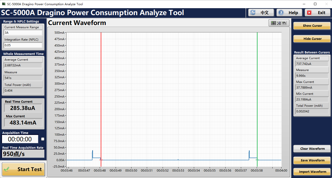
2. The power consumption for continuous wind speed measurement is as follows:
When AT+WINDMOD=1, the power consumption is:
- Current and duration of a sampled data set: Current 737.742uA, Duration: 9.966s
- Total power consumption is: 0.002042 mAh
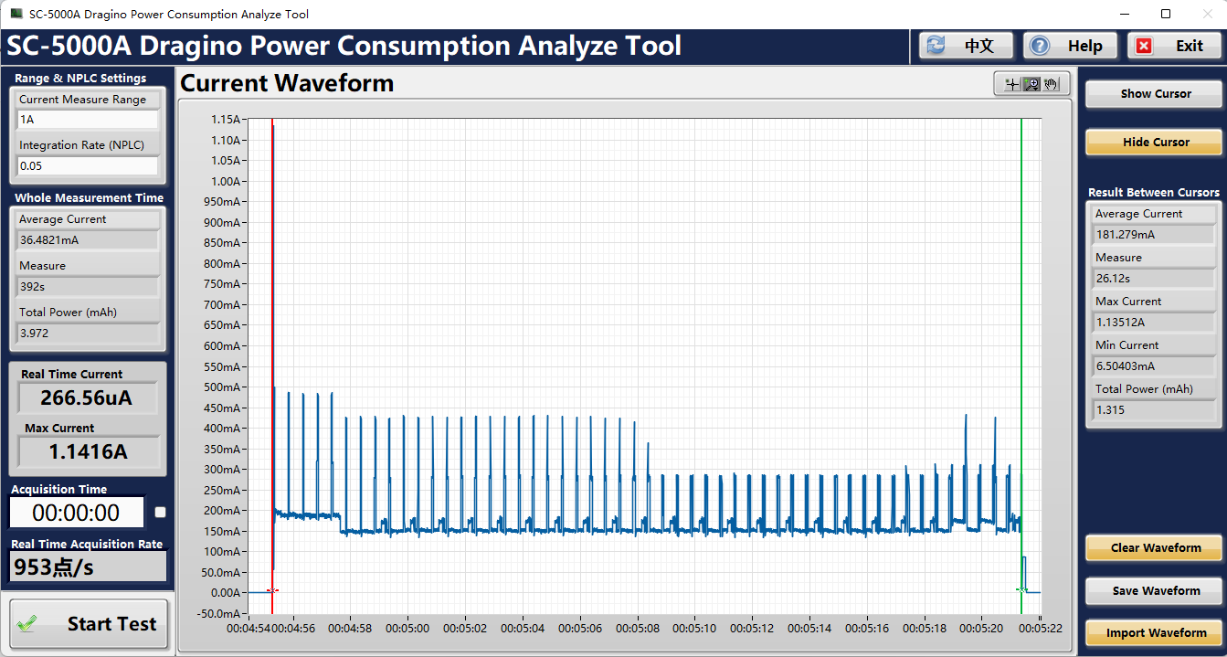
When AT+WINDMOD=2 and AT+WINDT=20, the power consumption is as follows:
- Current and duration of a sampled data set: Current 181.279mA, Duration: 26.12s
- Total power consumption is: 1.315 mAh
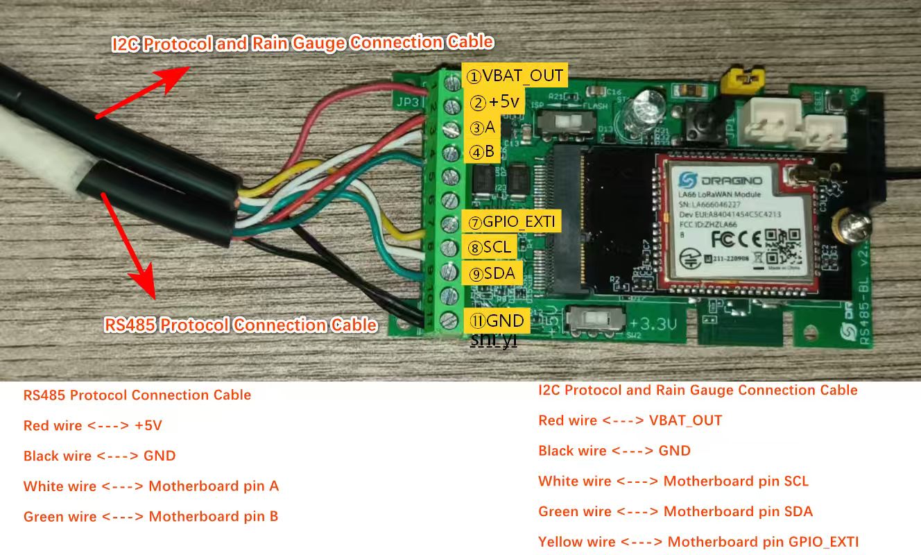
3.4.7.4 Wiring Method(Configure AT+WSS=1,1,1,1,1)
Note: Since the WSC2-Compact-LS uses the I2C protocol as its default sensor communication protocol, but the wind speed and direction sensor, TSR, PAR, and soil sensor utilize the RS485 protocol, an additional DR-F6C-4 cable must be added to the existing setup.
4. Power consumption & Battery
The WSC2-Compact-LS uses a 3000mAh lithium battery and a solar panel. For battery information and details on how to replace the battery, see the following links:
AI Calculation Battery Life Instructions
Here are the currents and durations of the WSC2-Compact-LS device for different transmission rates:
4.1 Calculate battery lifespan using AI
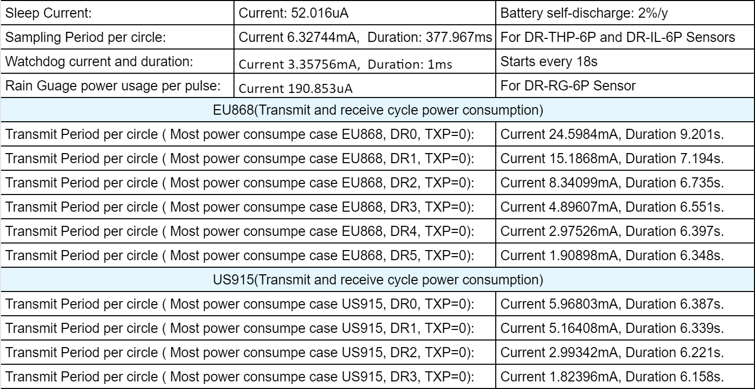
Example queries to ask AI:
Sleep Current: 52.016uA Battery self-discharge: 2%/y (Li-ion Battery) Sampling Period per circle: Current 6.32744mA, Duration: 377.967ms Watchdog current and duration: Current 3.35756mA, Duration: 1ms Rain Guage power usage per pulse: Current 190.853uA Transmit Period per circle ( Most power consumpe case EU868, DR0, TXP=0): Current 24.5984mA, Duration 9.201s. Transmit Period per circle ( Most power consumpe case EU868, DR1, TXP=0): Current 15.1868mA, Duration 7.194s. Transmit Period per circle ( Most power consumpe case EU868, DR2, TXP=0): Current 8.34099mA, Duration 6.735s. Transmit Period per circle ( Most power consumpe case EU868, DR3, TXP=0): Current 4.89607mA, Duration 6.551s. Transmit Period per circle ( Most power consumpe case EU868, DR4, TXP=0): Current 2.97526mA, Duration 6.397s. Transmit Period per circle ( Most power consumpe case EU868, DR5, TXP=0): Current 1.90898mA, Duration 6.348s. Uplink Interval : 20min Battery Capacity: 3000mAh 10,000 triggers per day Can you please help me calculate the average current and battery life for the different DRs above?
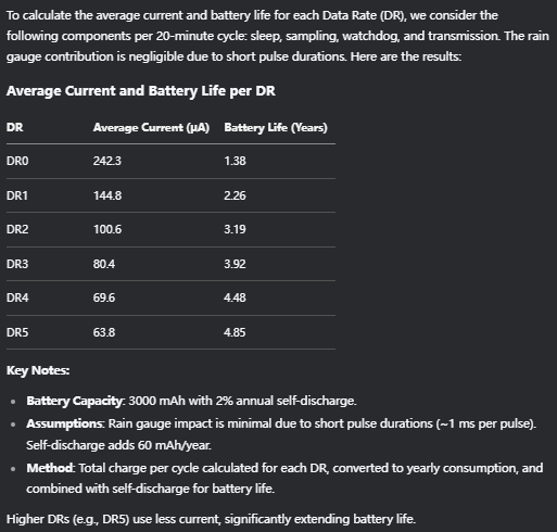
AI Response Example:
4.2 Solar charging instructions
Battery capacity 3000mAh, maximum charging power of solar panel: 0.9W, charging efficiency: 22 Normally it takes 56 hours of charging to fill the battery when the sun is right on the solar panel at midday. The specific calculation process is as follows:
1. Battery energy capacity calculation The battery voltage is 3.7v, the total energy is:
- 3000mAh × 3.7v = 11.1Wh
2. Effective charging power calculation The maximum power of the solar panel is 0.9W, the charging efficiency is 22%, the actual power input to the battery is:
- 0.9W × 22% = 0.198W
3. Charging time calculation Time T = total energy ÷ effective power = Total charging time
- 11.1Wh ÷ 0.198W ≈ 56.06 hours
5. OTA Firmware update
User can change firmware WSC2-Compact-LS to:
- Change Frequency band/ region.
- Update with new features.
- Fix bugs.
Firmware and changelog can be downloaded from : Firmware download link
Methods to Update Firmware:
-
(Recommended way) OTA firmware update via wireless: /docs/wiki/Configuration/end-node/lorawan-ota-firmware/
-
Update through UART TTL interface: Instruction.
6. FAQ
6.1 Why does the rain gauge have no data?
The WSC2-Compact-LS ships with the rain gauge set to counting mode by default (AT+COUNTMOD=1). In this mode, rainfall data is accumulated and reported in the uplink payload.
If you are not receiving rainfall data, it may be because the device has been accidentally switched to interrupt mode (AT+COUNTMOD=0). In interrupt mode, the device only sends an uplink trigger when rain is detected, without including rainfall count data.
Solution: Check the current rain gauge mode and reset it to counting mode if necessary.
- AT Command:
| Command Example | Function | Response |
|---|---|---|
| AT+COUNTMOD=0 | set to interrupt mode | OK |
| AT+COUNTMOD=1 | set to counting mode | OK |
- Downlink Command:
Format: Command Code (0x10) followed by 1 bytes time value.
- Example 1: Downlink Payload: 10 00 // Same as: AT+COUNTMOD=0 set to interrupt mode
- Example 2: Downlink Payload: 10 01 // Same as: AT+COUNTMOD=1 set to counting mode
6.2 Why is there no LED response when I press the button on the solar panel model?
If the LED does not light up when you press the button, it may be because the battery has entered protection mode.
Solution: To reactivate the battery, simply expose the solar panel to direct sunlight. For more details, please refer to: Battery Protection State (Apply to Solar Panel + Li-ion battery)
7. Order Info
Please note that the WSC2-Compact series only includes the wireless transmitter, the 3 in 1 sensor, Illuminance sensor and rain guage need to be purchased separately.
Part Number:
Wireless Transmitter: WSC2-Compact-LS-XX Sensors Option : DR-THP-6P , DR-IL-6P , DR-RG-6P
XX: The default frequency band
- AS923: LoRaWAN AS923 band
- AU915: LoRaWAN AU915 band
- EU433: LoRaWAN EU433 band
- EU868: LoRaWAN EU868 band
- KR920: LoRaWAN KR920 band
- US915: LoRaWAN US915 band
- IN865: LoRaWAN IN865 band
- CN470: LoRaWAN CN470 band
8. Packing Info
Packing Includes:
- WSC2-Compact-LS LoRaWAN Weather Station Kit
Dimension and weight:
-
Device Size: cm
-
Device Weight: g
-
Package Size / pcs : cm
-
Weight / pcs : g
9. Support
-
Support is provided Monday to Friday, from 09:00 to 18:00 GMT+8. Due to different timezones we cannot offer live support. However, your questions will be answered as soon as possible in the before-mentioned schedule.
-
Provide as much information as possible regarding your enquiry (product models, accurately describe your problem and steps to replicate it etc) and send a mail to support@dragino.com.
0