LHT65N-VIB
1. Introduction
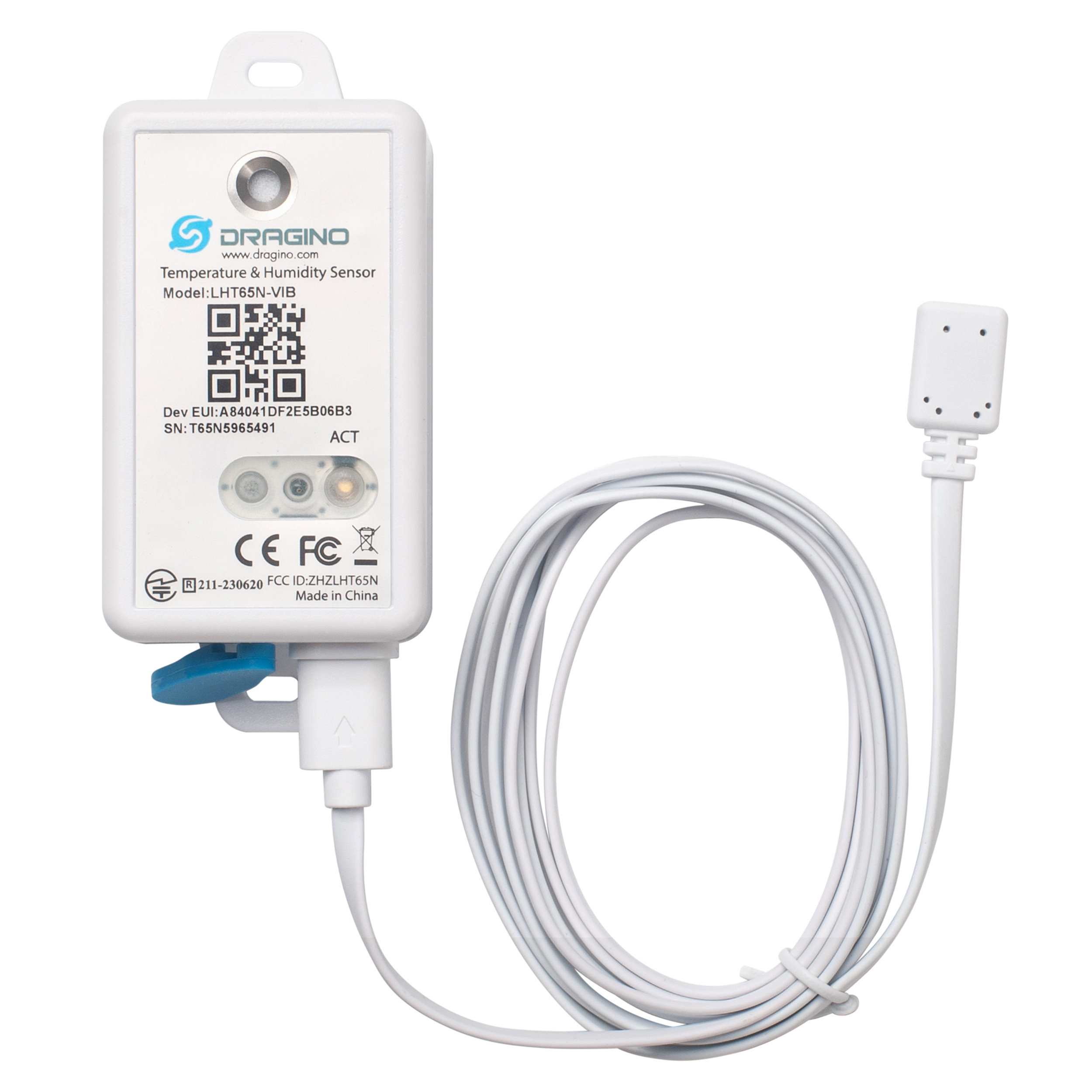
1.1 What is the LHT65N-VIB LoRaWAN Vibration Sensor?
The Dragino LHT65N-VIB LoRaWAN Vibration Sensor is designed to detect and measure vibrations, shocks, and accelerations of an object. By analyzing the object's motion, the LHT65N-VIB can send meaningful data such as alarms, device runtime, vibration counts, and vibration strength to an IoT platform for further analysis.
It can be used in professional wireless sensor network applications, including equipment status monitoring, water leakage alarms, usage statistics, vibration intensity detection, and more.
The LHT65N-VIB supports a datalogging feature, allowing it to record data when there is no network coverage. Users can retrieve the sensor readings later, ensuring no data is missed.
The LHT65N-VIB enables users to send data over extremely long distances. It offers ultra-long-range spread spectrum communication and high interference immunity while minimizing current consumption.
The LHT65N-VIB has a** built-in 2400mAh non-rechargeable battery**, which can last up to 3 years*.
The LHT65N-VIB is fully compatible with the LoRaWAN v1.0.3, Class A mode and can work with a standard LoRaWAN gateway.
*The actual battery life depends on how frequently data is transmitted. Please refer to the battery analyzer chapter for more details.
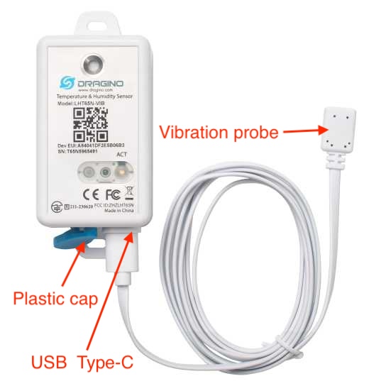
1.2 Assembling the vibration probe
The LHT65N-VIB is sold with an external vibration sensor probe. The vibration sensor probe can be connected to the LHT65N-VIB using the USB Type-C connector. You can find the USB Type-C port on the LHT65N-VIB after removing the blue plastic cap.
1.2 Features
- LoRaWAN v1.0.3, Class A mode
- Frequency Bands: CN470, EU433, KR920, US915, EU868, AS923, AU915
- Detects object vibration status
- Detects vibration alarms
- 3-axis accelerometer for x, y, z axes
- Calculates device runtime
- Built-in 2400mAh battery for long-term use
- Built-in temperature and humidity sensor
- Tri-color LED to indicate working status
- Datalog feature (up to 3328 records)
- AT commands to change parameters
- Remote configuration of parameters via LoRaWAN downlink
- Firmware upgradeable via programming port
1.3 Specification
Built-in Temperature Sensor:
- Resolution: 0.01 °C
- Accuracy tolerance : Typ ±0.3 °C
- Long Term Drift: < 0.02 °C/yr
- Operating range: -40 ~ 85 °C
Built-in Humidity Sensor:
- Resolution: 0.04 %RH
- Accuracy tolerance : Typ ±3 %RH
- Long Term Drift: < 0.25 RH/yr
- Operating range: 0 ~ 96 %RH
External Vibration Sensor:
- Detecting object vibration status
- accelerator for x,y,z
- Small size for easy installation
- Acceleration: ±2g,±4g,±8g;±16g
- Frequency: 25 Hz, 50 Hz,100 Hz, 200 Hz, 400 Hz
2. Registering LHT65N-VIB with a LoRaWAN Network Server
The LHT65N-VIB can be registered with any LoRaWAN network server. In this documentation, we use The Things Stack as an example, but similar settings may apply to other LoRaWAN network servers.
2.1 How does the LHT65N-VIB work?
The LHT65N-VIB is configured in LoRaWAN Class A mode by default. Each LHT65N-VIB is shipped with a unique global registration key that supports OTAA (Over-The-Air-Activation). To use the LHT65N-VIB with a LoRaWAN network, you first need to register the device with the network using the provided registration keys for OTAA support.
The LHT65N-VIB's registration information can be found inside the device package.
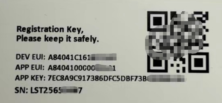
The registration information includes the following:
- DevEUI
- AppEUI
- AppKey
Once registered, if the LHT65N-VIB is within the coverage area of the LoRaWAN network, it can automatically join the network. After successfully joining, the LHT65N-VIB will begin measuring environmental temperature and humidity and will start transmitting sensor data to the LoRaWAN network server. The default uplink transmission interval is 20 minutes.
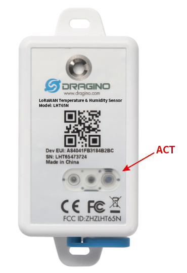
2.2 How to Activate LHT65N-VIB?
The LHT65N-VIB has two modes:
Deep sleep mode: In this mode, the LHT65N-VIB doesn't perform any LoRaWAN activation. It is used for storage and shipping to conserve battery life.
- Working mode: In this mode, the LHT65N-VIB works as a LoRaWAN sensor, joining the LoRaWAN network and sending sensor data to the server. Between each sampling/TX/RX cycle, the LHT65N-VIB enters STOP mode (IDLE mode), where it consumes the same power as in deep sleep mode.
The LHT65N-VIB is set in deep sleep mode by default. The ACT button on the front can be used to switch between different modes. See the image below:
| Behavior on ACT | Function | Action |
|---|---|---|
| Test uplink status | If LHT65N-VIB is already joined to the LoRaWAN network, it will send an uplink packet. If an external sensor is connected, the Blue LED will blink once. If there is no external sensor, the Red LED will blink once. | |
| Activate Device | The** Green LED** will blink quickly 5 times, indicating that the LHT65N-VIB is entering working mode and starting to join the LoRaWAN network. The Green LED will solid for 5 seconds after successfully joining the network. | |
| Deactivate Device | The Red LED will remain solid for 5 seconds, indicating that the LHT65N-VIB is in Deep Sleep Mode. |
Information
We recommend that you activate the device using the ACT button after adding its registration information to the LoRaWAN network server. Otherwise, the device will continuously send join-request messages in an attempt to join a LoRaWAN network but will fail.
2.3 Registering with The Things Stack
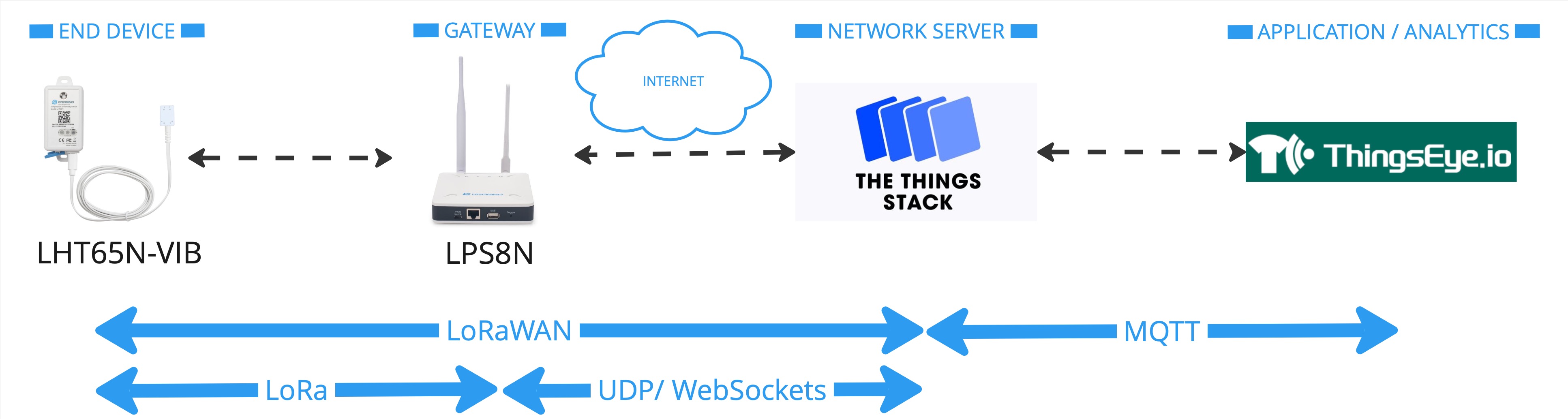
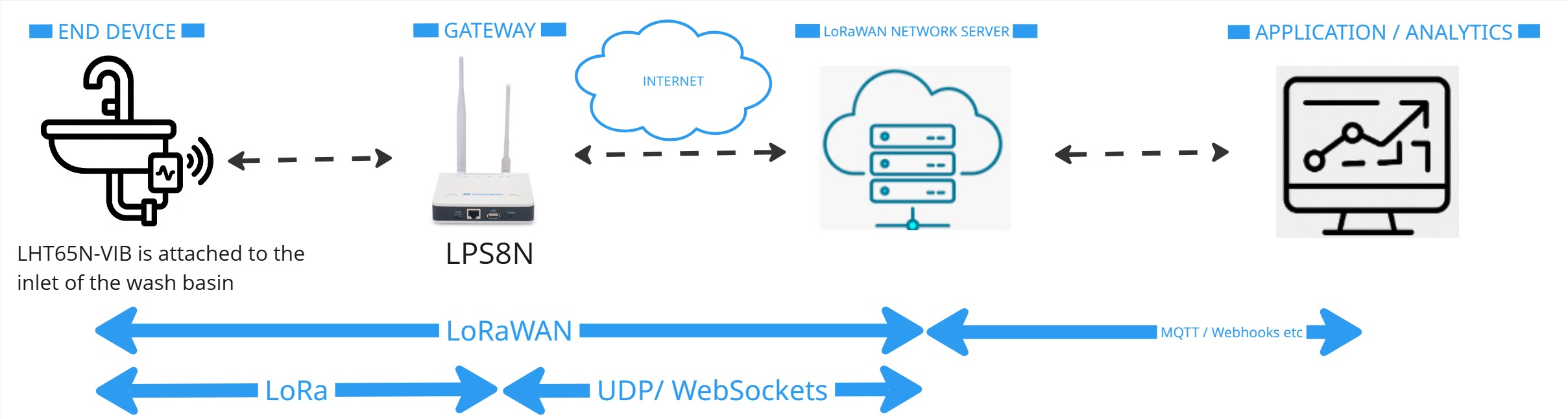
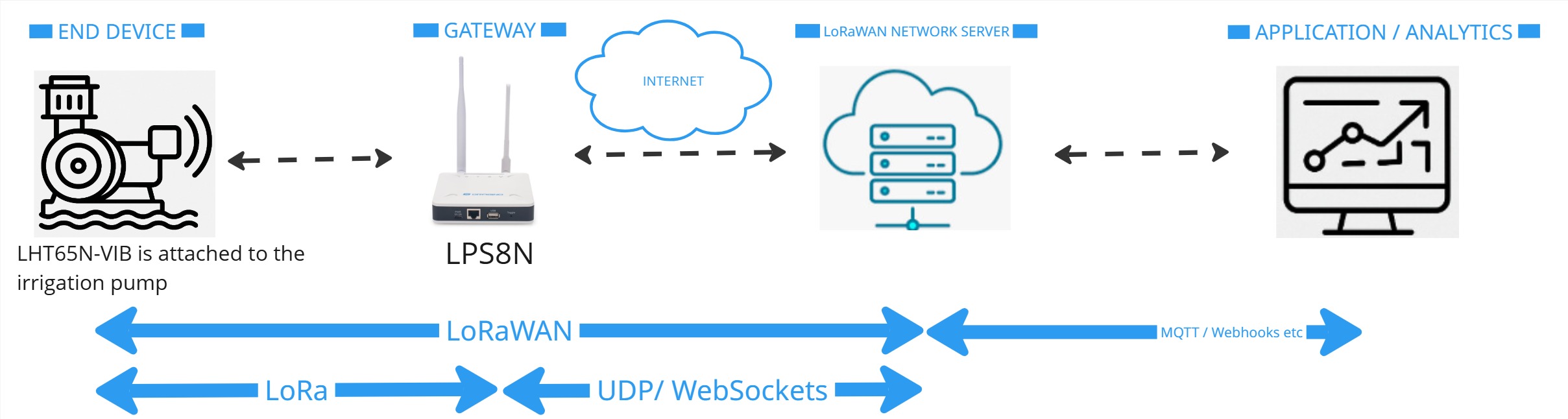
In this section we will guide you through on how to register the LHT65N-VIB with The Things Stack. If your area has The Things Stack community network coverage, you can use it without setting up your own network. If not, you can set up your own LoRaWAN network coverage by using our LPS8N LoRaWAN gateway.
The typical end-to-end network setup with LHT65N-VIB and LPS8v2 is shown below:
2.3.1 Add LHT65N-VIB to The Things Stack
- From the LoRaWAN device repository
- Manually
2.3.1.1 Creating an application
Sign up for a free account with The Things Stack Sandbox if you do not have one yet. Then, create an application as shown in the screenshots below.
2.3.1.2 Adding using the LoRaWAN device repository
You can refer to the screenshots below to register your LHT65N-VIB using The Things Stack's LoRaWAN device repository.
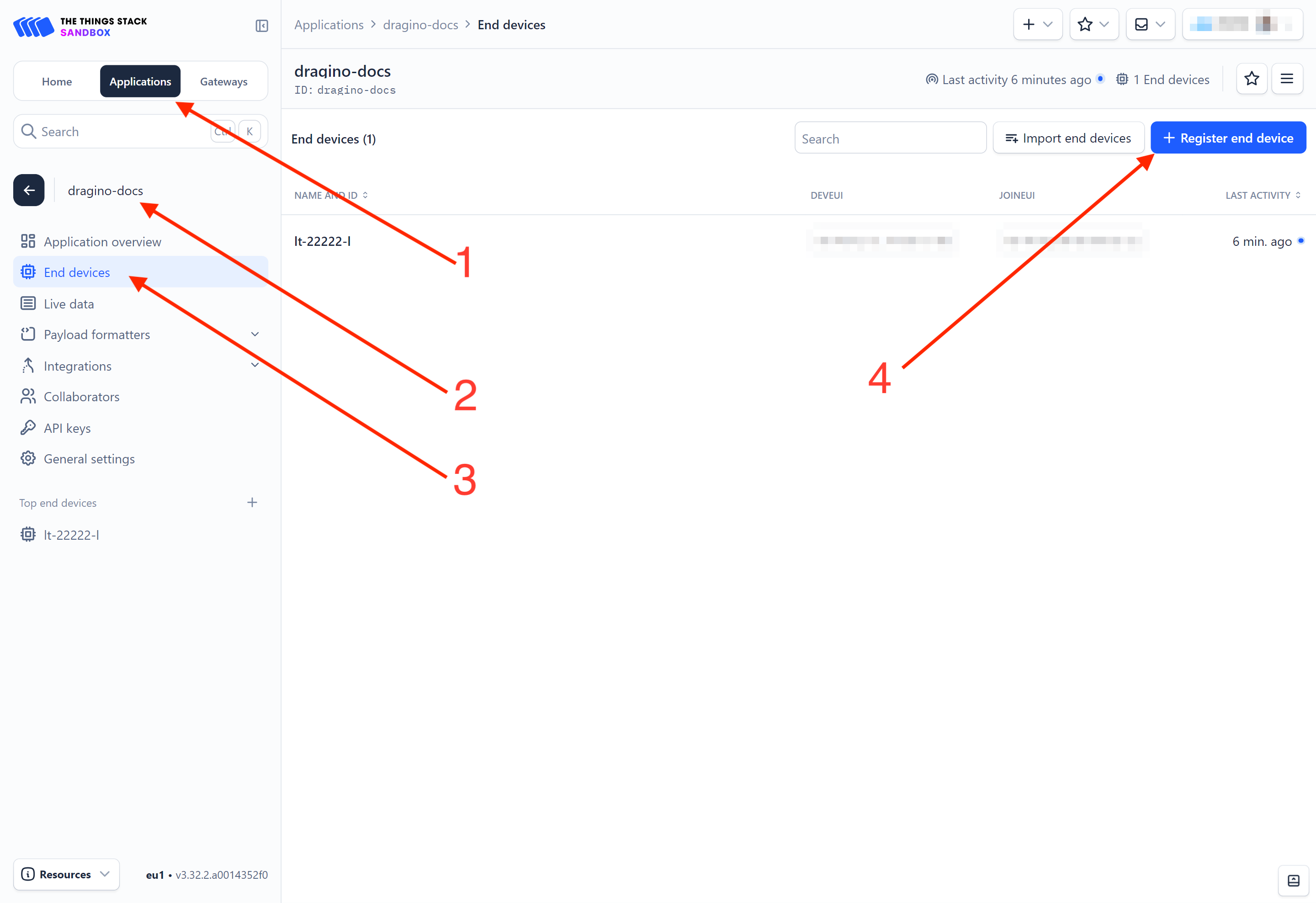
On The Things Stack console:
1. Click Applications.
2. Click <your application>. E.g. dragino-docs
3 Click End devices.
4. Click + Register end device button.
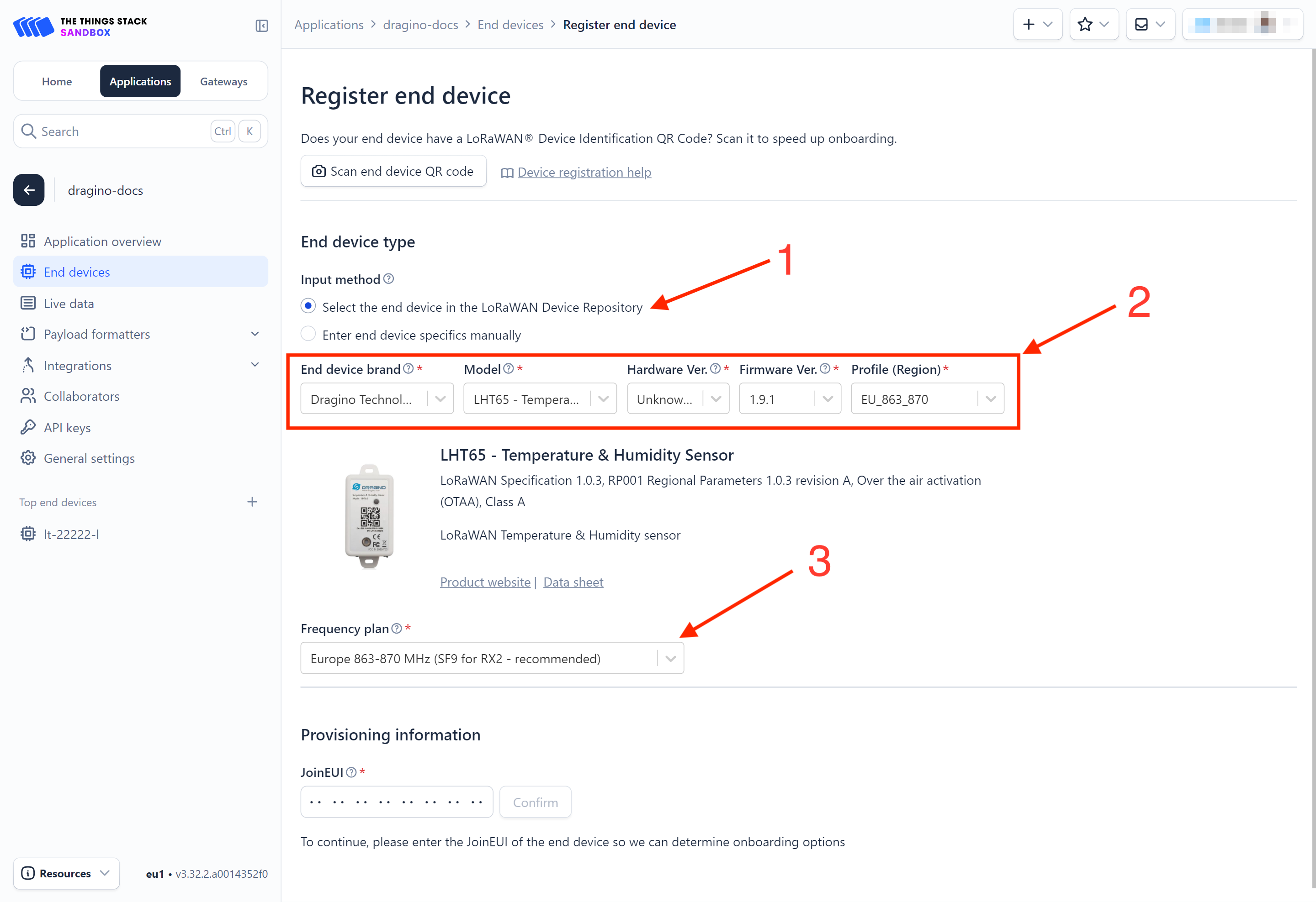
On the Register end device page:
1. Click Select the end device in the LoRaWAN Device Repository option.
2. Select the following parameters:
- End device brand: Dragon Technology Co., Limited
- Model: LHT65 - Temperature and Humidity Sensor. The LHT65N-VIB Vibration Sensor uses the same template as the LHT65 - Temperature and Humidity Sensor.
- Hardware Ver: Unknown Ver.
- Firmware Ver: 1.9.1
- Profile (Region): Select the region that matches your device. E.g.: EU_863_870
3. Frequency plan: Select the frequency plan that matches your device. E.g.: Europe 863-870 MHz (SF9 for RX2 - recommended).
4. JoinEUI: Enter the AppEUI of the device (see the registration information sticker) and Click the Confirm button.
5. DevEUI: Enter the DevEUI of the device (see the registration information sticker).
6. AppKey: Enter the AppKey of the device (see the registration information sticker).
7. End device ID: Enter a name for your end device to uniquely identify it within this application.
8. Click View registered end device option.
9. Click Register end device button.
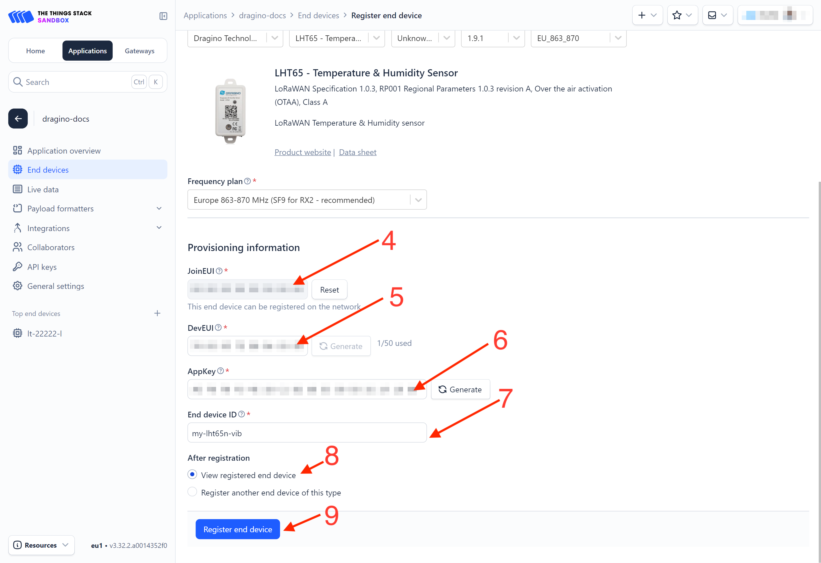
You will be navigated to the **Device overview **page.
2.3.1.3 Adding manually
You can refer to the screenshots below to register your LHT65N-VIB using The Things Stack's manual option.
1-4: Same as in the section 3.2.2.2.
5. Select Enter end device specifies manually option.
6. Frequency plan: Select the frequency plan that matches your device. E.g.: Europe 863-870 MHz (SF9 for RX2 - recommended).
7. LoRaWAN version: LoRaWAN Specification 1.0.3
8. Regional Parameters version: You can't change it and it will select automatically.
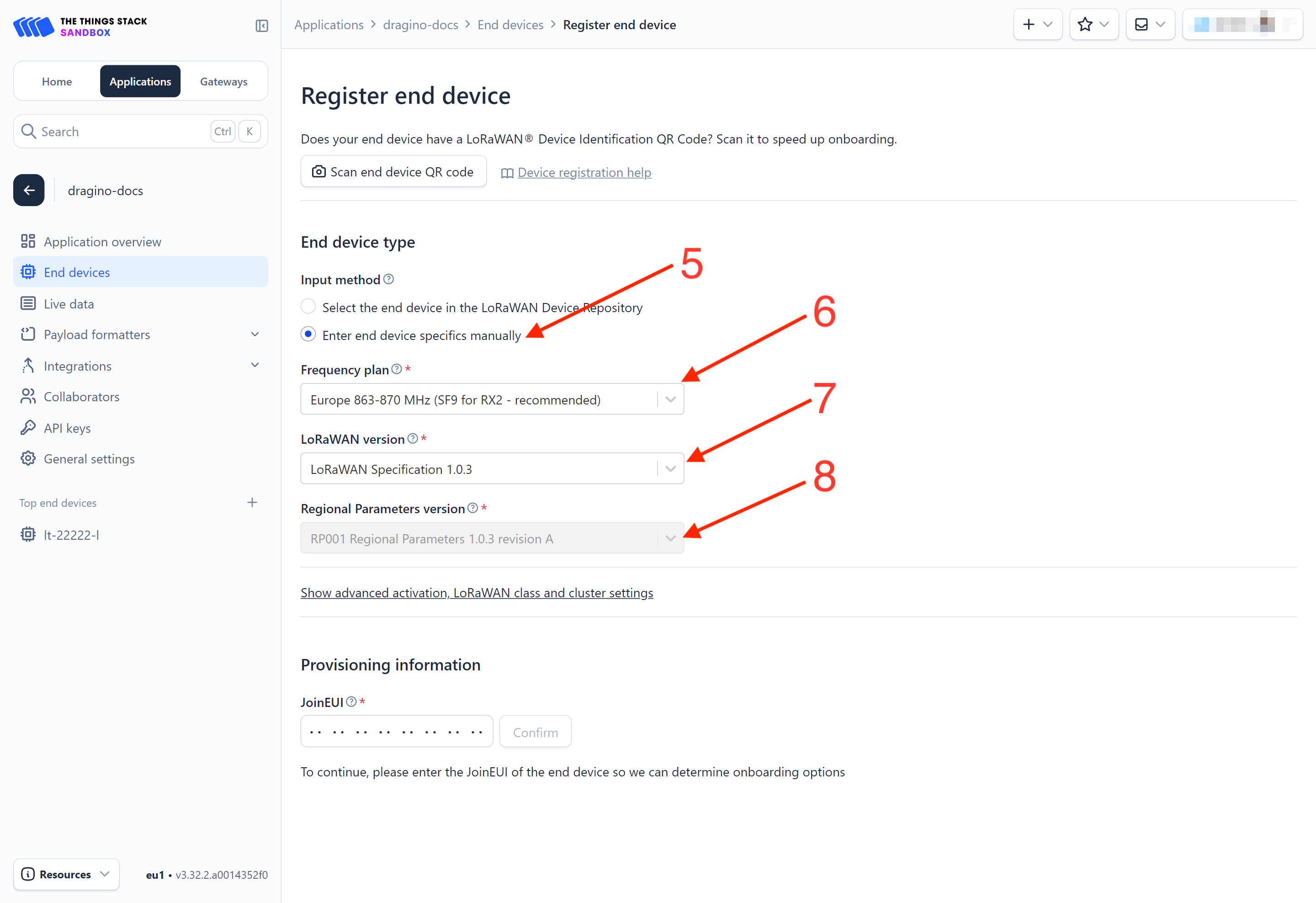
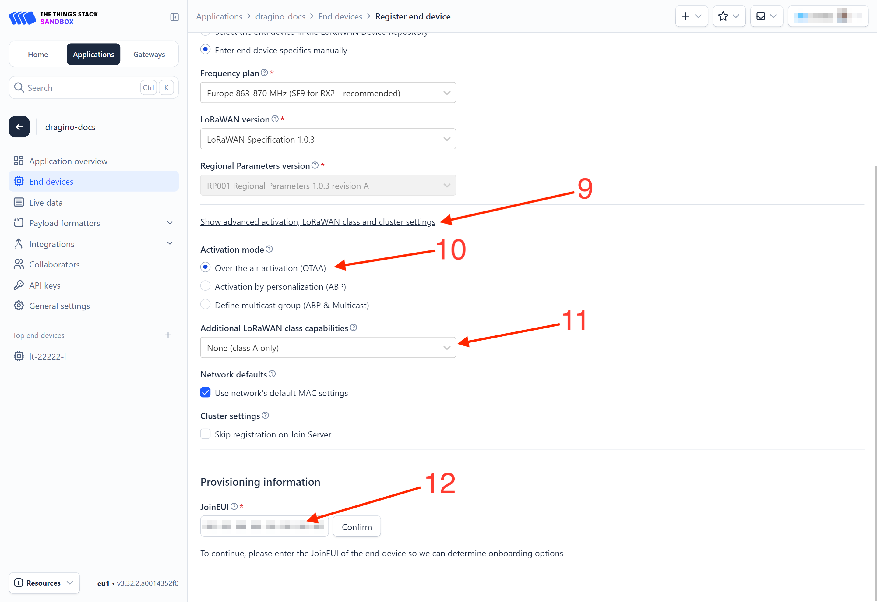
9. Click on the **Show advanced activation, LoRaWAN class and cluster settings **to expand the section.
10. Select Over the air activation (OTAA) option.
11. Select None (class A only).
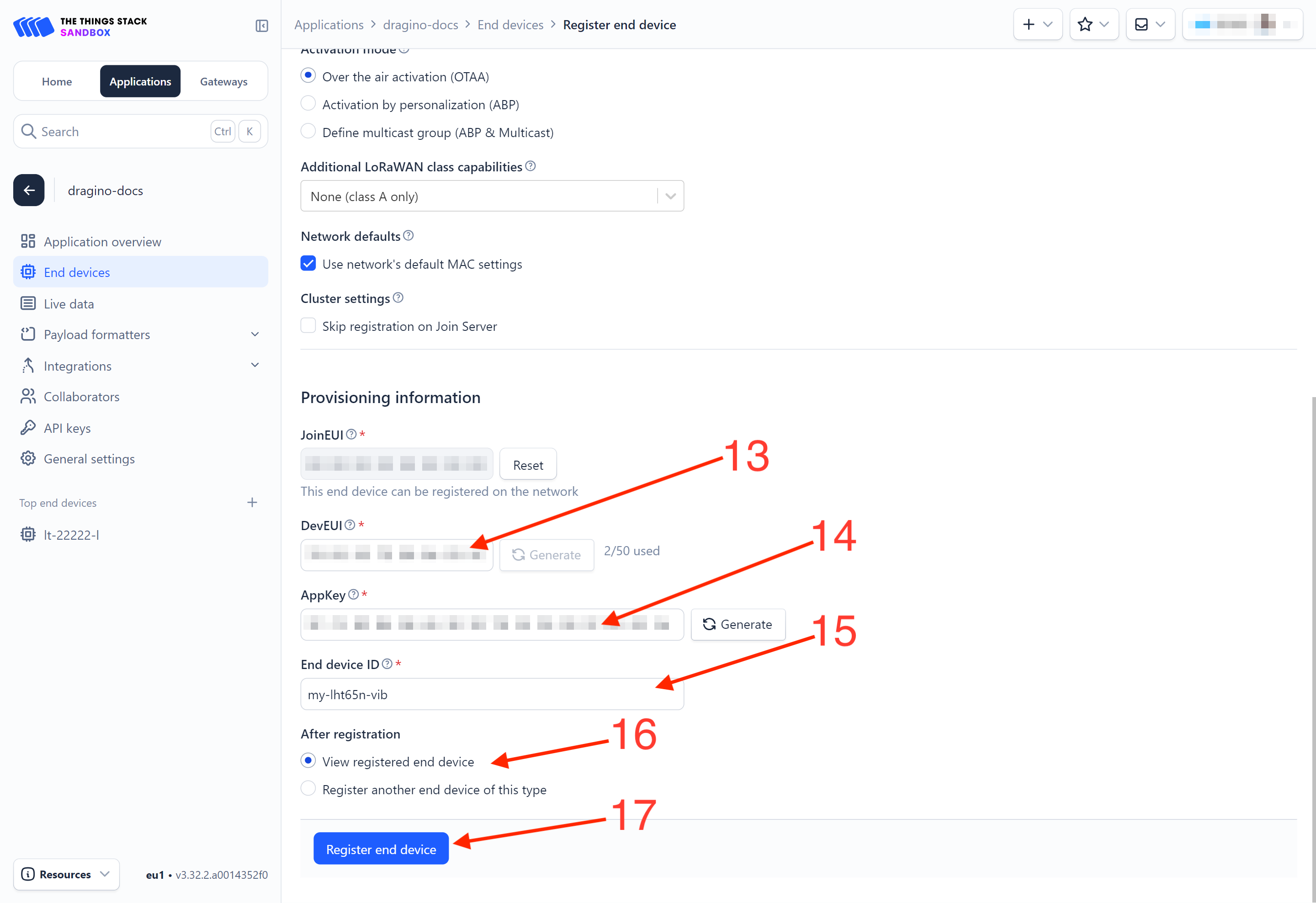
12. JoinEUI: Enter the AppEUI of the device (see the registration information sticker) and Click the Confirm button.
- DevEUI: Enter the DevEUI of the device (see the registration information sticker).
14. AppKey: Enter the AppKey of the device (see the registration information sticker).
15. End device ID: Enter a name for your end device to uniquely identify it within this application.
16. Click View registered end device option.
17. Click Register end device button.
You will be navigated to the **Device overview **page.
2.3.2 Activate the LHT65N-VIB by pressing and holding the ACT button for more than 5 seconds.
Press and hold the ACT button for more than 5 seconds to activate the LHT65N-VIB. It will then join The Things Stack. Once successfully connected, the device will begin uplinking sensor data to The Things Stack, which can be viewed on the Live data panel.
2.3.3 Uplink Decoder in The Things Stack
When the uplink payload arrives in The Things Stack, it is displayed in HEX format, which is not easy to read. You can add the LHT65N-VIB decoder in The Things Stack for easier readability of each sensor readings.
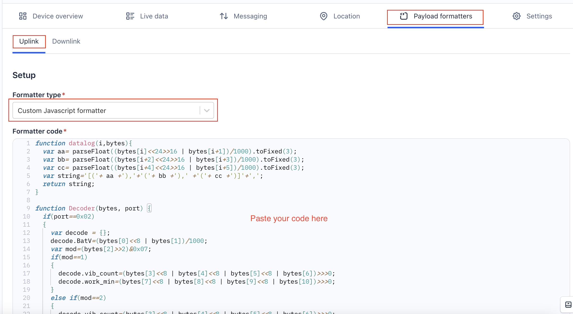
The uplink decoder can be added to the** Payload Formatters** of your device in The Things Stack. Refer to the screenshot below.
1. Click Uplink tab.
2. Formatter type: Select Custom Javascript formatter.
3. Formatter code: Copy the uplink payload formatter code from our dragino-end-node-decoder GitHub repository and paste it here.
4. Finally, click on the Save changes button.
2.4 Uplink Payload (FPort=2)
The uplink payload is a total of 11 bytes. Uplink packets use **FPort=2 **and, by default, are sent every 20 minutes.
After each uplink, the BLUE LED blinks once.
There are four different working modes, and the uplink payload format varies for each mode:
- VIBMOD=1 : vib_count, work_min
- VIBMOD=2 : TempC_SHT, Hum_SHT, vib_count
- VIBMOD=3 : TempC_SHT, Hum_SHT, work_min
- VIBMOD=4 : X, Y, Z
2.4.1 VIBMOD=1 : Vibration Count, Run Time
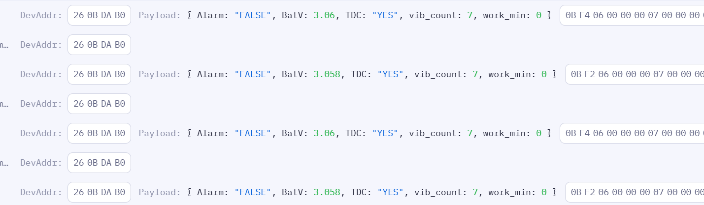
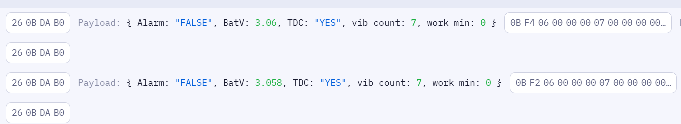
VIBMOD=1 represent the battery voltage, working mode, alarm status, TDC, vibration count, and work_min. The uplink payload is shown below.
| Size(bytes) | 2 | 1 | 4 | 4 |
|---|---|---|---|---|
| Value | BAT | MOD Alarm TDC | vib_count | work_min |
The following subsections describe each field:
2.4.1.1 BAT (Battery Voltage)
These two bytes represent the battery voltage. See the image below.
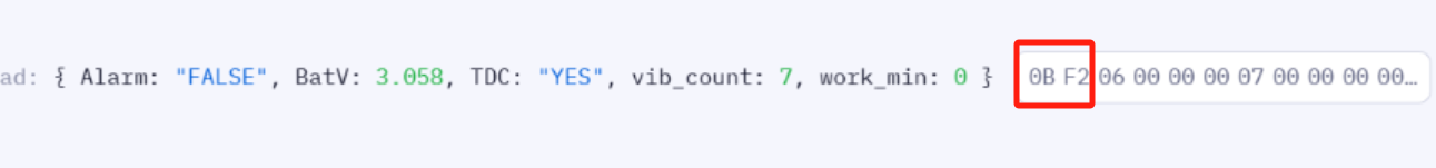
Calculate the battery voltage for the LHT65N-VIB, if the BAT=0B F2.
Convert 0x0BF2 to decimal (3058) and then divide by 1000 to get the voltage.
- 0x0BF2 (hex) = 3058 (dec)
- 3058/1000 = 3.058 V
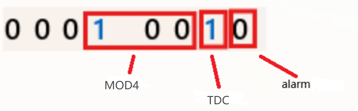
2.4.1.2 MOD, Alarm, and TDC
This byte represent working mode, alarm status, and TCD. See the image below.
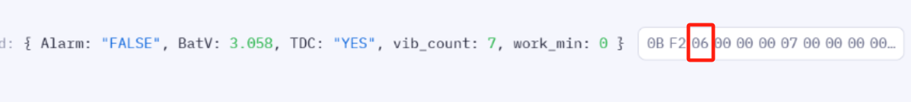

bytes[2]=0x06=0000 0110
Current working mode:
- (bytes[2]>>2)&0x07
- Shift two bits to right (0000 0110 -> 0000 0001)
- Then bitwise AND with 0x07 (0000 0001 & 0000 0111 = 0000 0001 = 1)
Current alarm status:
- (bytes[2] & 0x01)? "TRUE":"FALSE"
- 0000 0110 & 0000 0001 = 0000 0000 = 0 = FALSE
Is the current data triggered by TDC (data uploaded due to alarm)?
- (bytes[2] & 0x02)? "YES":"NO"
- 0000 0110 & 0000 0010 = 0000 0010 = 2 (NON-ZERO VALUE) = YES
2.4.1.3 vib_count
These 4 bytes (vib_count) represent the number of vibration events that has been recorded. See the image below.
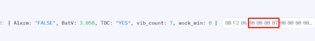
- 0x00000007=7
2.4.1.4 work_min
These 4 bytes (work_min) indicate the duration the current vibration sensor has been active since the latest trigger. See the image below.

- 0x00000000=0
0 means that the current vibration sensor is not triggered.
2.4.2 VIBMOD=2 : Vibration Count,Temperature,Humidity
VIBMOD=2 represent the battery voltage, working mode, alarm status, TDC, vibration count, TempC_SHT, and Hum_SHT. The uplink payload is shown below.
| Size(bytes) | 2 | 1 | 4 | 2 | 2 |
|---|---|---|---|---|---|
| Value | BAT | MOD Alarm TDC | vib_count | TempC_SHT | Hum_SHT |
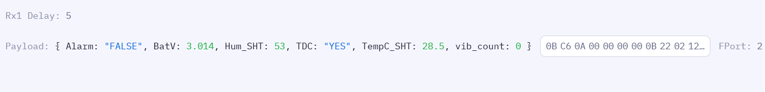
2.4.2.1 BAT (Battery Voltage)
These two bytes represent the battery voltage. See the image below.

Calculate the battery voltage for LHT65N-VIB.
- 0x0BC6/1000=3.014V
2.4.2.2 VIBMOD, Alarm and TDC
This byte represent working mode, alarm status, and TCD. See the image below.
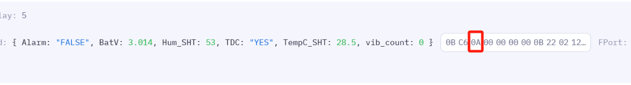
bytes[2]=0x0A=0000 0101
Current working mode=(bytes[2]>>2)&0x07=2
Current alarm situation= (bytes[2] & 0x01)? "TRUE":"FALSE";=0=FALSE
Whether the current data occurs is TDC (the data will be uploaded by the alarm)= (bytes[2] & 0x02)? "YES":"NO";=00000010 (non -zero value)=YES
2.4.2.3 vib_count
These 4 bytes represent the number of vibration events that has been recorded. See the image below.

- 0x00000000=0
2.4.2.4 TempC_SHT
These 2 bytes represent the temperature measured by the built-in temperature & humidity sensor, SHT31.

- 0x0B22/100=28.5°C
2.4.2.5 Hum_SHT
These 2 bytes represent the humidity measured by the built-in temperature & humidity sensor, SHT31.

- 0x0212/10=53%
2.4.3 VIBMOD=3: Run Time,Temperature,Humidity
VIBMOD=3 represents the battery voltage, working mode, alarm status, TDC, TempC_SHT, Hum_SHT, and work_min. The uplink payload is shown below.
| Size(bytes) | 2 | 1 | 2 | 2 | 4 |
|---|---|---|---|---|---|
| Value | BAT | MOD Alarm TDC | TempC_SHT | Hum_SHT | work_min |

2.4.3.1 BAT (Battery Voltage)
These 2 bytes represent the battery voltage.

- 0x0BC2/1000=3.01V
2.4.3.2 VIBMOD and Alarm and TDC
This byte represents the working mode, alarm status, and TDC.

bytes[2]=0x0A=0000 1110
Current working mode=(bytes[2]>>2)&0x07=3
Current alarm situation= (bytes[2] & 0x01)? "TRUE":"FALSE";=0=FALSE
Whether the current data occurs is TDC (the data will be uploaded by the alarm)= (bytes[2] & 0x02)? "YES":"NO";=00000010 (non -zero value)=YES
2.4.3.3 TempC_SHT
These 2 bytes represent the temperature measured by the built-in temperature & humidity sensor, SHT31.

- 0x0B21/100=28.49 ℃
2.4.3.4 Hum_SHT
These 2 bytes represent the humidity measured by the built-in temperature & humidity sensor, SHT31.

- 0x0213/10=53.1%
2.4.3.5 work_min
These 4 bytes (work_min) indicate the duration the current vibration sensor has been active since the latest trigger. See the image below.

- 0x00000000=0
0 means that the current vibration sensor is not triggered.
2.4.4 VIBMOD=4 :Three-axis X-Y-Z vibration data(FPort=7)
VIBMOD=4 represents the battery voltage and multiple groups of accelerometer data. The uplink payload structure is shown below.
| Size(bytes) | 2 | 2 | 2 | 2 | 2 | 2 | 2 | ... |
|---|---|---|---|---|---|---|---|---|
| Value | BAT | X1 | Y1 | Z1 | X2 | Y2 | Z2 | ... |
Where:
- BAT: Battery voltage (2 bytes)
- X1,Y1,Z1: First group of accelerometer data (2 bytes + 2 bytes + 2 bytes)
- X2,Y2,Z2: Second group of accelerometer data (2 bytes + 2 bytes + 2 bytes)
- ...: Additional groups may follow depending on collection settings

The first two bytes represent the battery voltage, for example 0B 4E.
The reset of the bytes represents the accelerometer data on axis X, Y, and Z. Each axis represent in 2 bytes.
The unit of measurement for these data is acceleration "g".
X = 0x03F5/1000=1.013g.
Y=0xFFE9/1000=-0.023g In binary, it is represented as 1111 1111 1110 1001. The highest bit is 1, indicating a negative number in two's complement notation, and its value is -0.023g.
Z=0xFEB2/1000=-0.334g In binary, it is represented as 1111 1110 1011 0010. The highest bit is 1, indicating a negative number in two's complement notation, and its value is -0.334g.
2.4.5 VIBMOD=5 Maximum acceleration during the detection time (FPort=9)(Enabled in the latest version 1.3)
VIBMOD=5 represents the battery voltage and maximum accelerometer data. The uplink payload structure is shown below.
| Size(bytes) | 2 | 2 | 2 | 2 | |
|---|---|---|---|---|---|
| Value | BAT | X-axis acceleration | Y-axis acceleration | Z-axis acceleration |

**BAT:**0x0CD8/100=3.288V
**x-axis:**0x00D0/100=0.208g
**y-axis:**0x0040/100=0.064g
**z-axis:**0x041C/100=1.052g
2.4.6 VIBMOD=6 Collision Detection(FPort=10)
| Size(bytes) | 2 | 2 | 2 | 2 | 3 |
|---|---|---|---|---|---|
| Value | BAT | X-axis acceleration | Y-axis acceleration | Z-axis acceleration | Three-axis state |
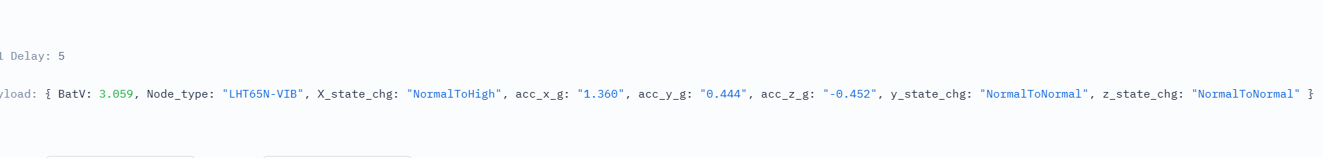
Example:0BF3 0550 01BC FE3C 86 05 05
**BAT:**0x0BF3/100=3.059V
**x-axis:**0x 0550/100=1.360g
**y-axis:**0x 01BC/100=0.444g
**z-axis:**0x FE3C/100=(65535-65084)/100=-0.452g
**x-axis:**0x86=1000 0110
**y-axis:**0x05=0000 0101
**z-axis:**0x05=0000 0101
Most Significant Bit (MSB):
- This bit indicates whether a state change has occurred on the X-axis that meets the requirements of the AT+ENQCTRL command.
- 1: Indicates Yes (requirement met).
- 0: Indicates No.
Decoder Formatting:
- If the MSB is 1, the decoder will display uppercase letters (X, Y, Z), e.g., X_state_chg.
- If the MSB is 0, the decoder will display lowercase letters (x, y, z), e.g., x_state_chg.
Lower 7 Bits:
-
These bits represent the specific nature of the state change (e.g., LowToLow, LowToNormal).
-
If the values on both sides of "To" are identical (e.g., xTox), it indicates that the acceleration state for that specific axis has not changed and the current state remains x.
-
Note: Each axis supports three distinct states: Low, Normal, and High.
2.5 Integrating with IoT platforms
The LHT65N-VIB sensor data can be integrated with other IoT platforms for better visualizing and analyzing the data. In this section, we will show you how to integrate sensor data from The Things Stack with some popular IoT platforms.
2.5.1 Integrate and show data on ThingsEye
The Things Stack application supports integration with ThingsEye.io. Once integrated, ThingsEye.io acts as an MQTT client for The Things Stack MQTT broker, allowing it to subscribe to upstream traffic and publish downlink traffic.
Information
The integration will link The Things Stack application (with all the devices) with ThingsEye. You can select sensor data fields from each device when creating the ThingsEye dashboards.
2.5.1.1 Configuring The Things Stack
We use The Things Stack Sandbox in this example:
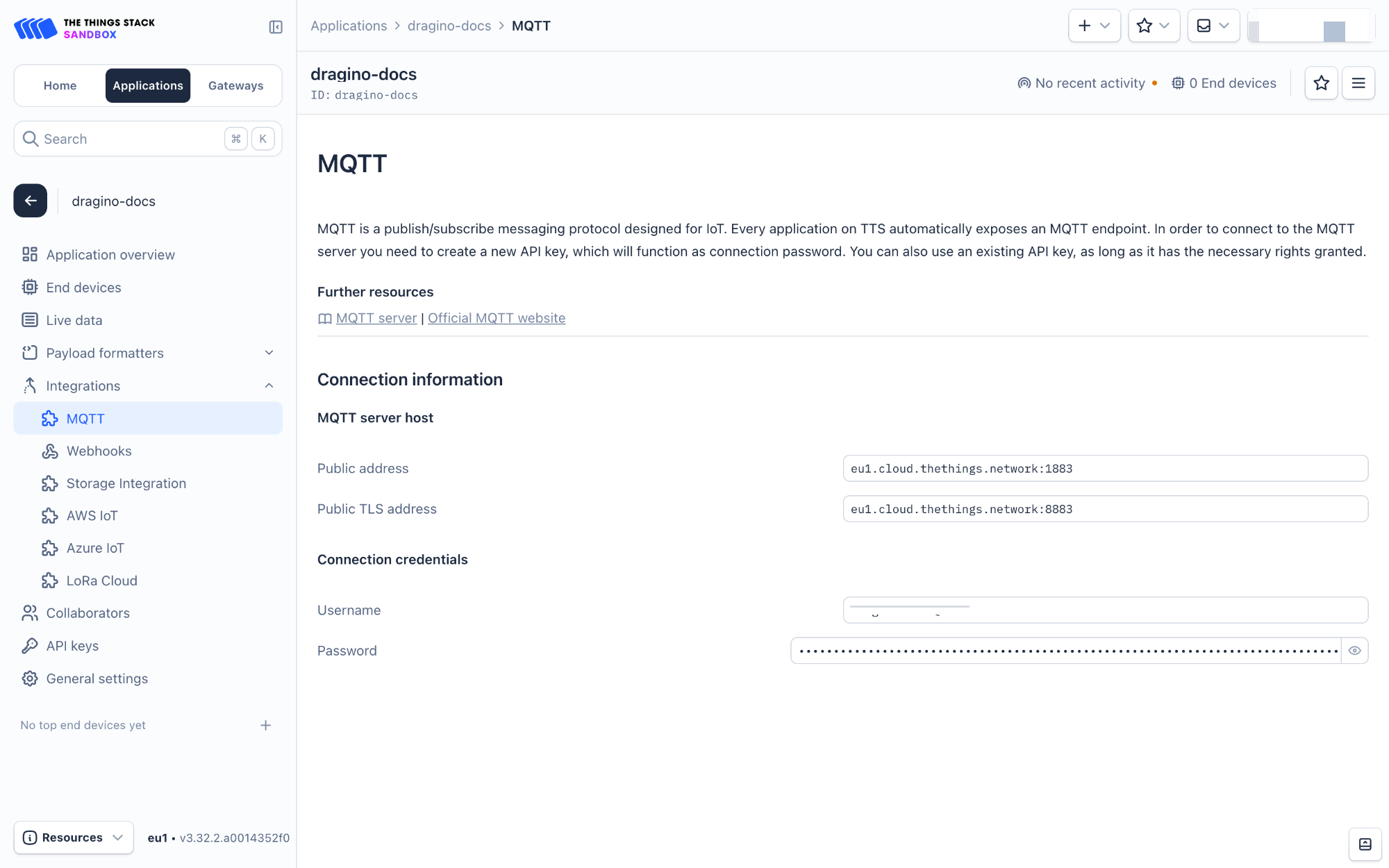
- In The Things Stack Sandbox, go to the **Application **for the LHT65N-VIB you added.
- Select MQTT under Integrations in the left menu.
- In the **Connection information **section, under Connection credentials, The Things Stack displays an auto-generated username. You can use it or provide a new one.
- Click the Generate new API key button to generate a password. You can view it by clicking on the visibility toggle/eye icon. The API key works as the password.
Information
The username and password (API key) you created here are required in the next section.
2.5.1.2 Configuring ThingsEye.io
The ThingsEye.io IoT platform is not open for self-registration at the moment. If you are interested in testing the platform, please send your project information to admin@thingseye.io, and we will create an account for you.
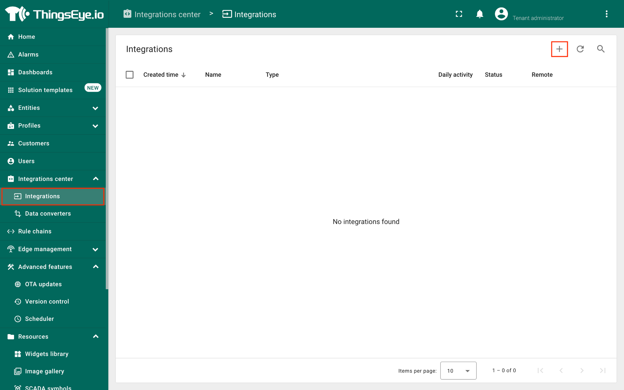
- Login to your ThingsEye.io account.
- Under the Integrations center, click Integrations.
- Click the Add integration button (the button with the + symbol).
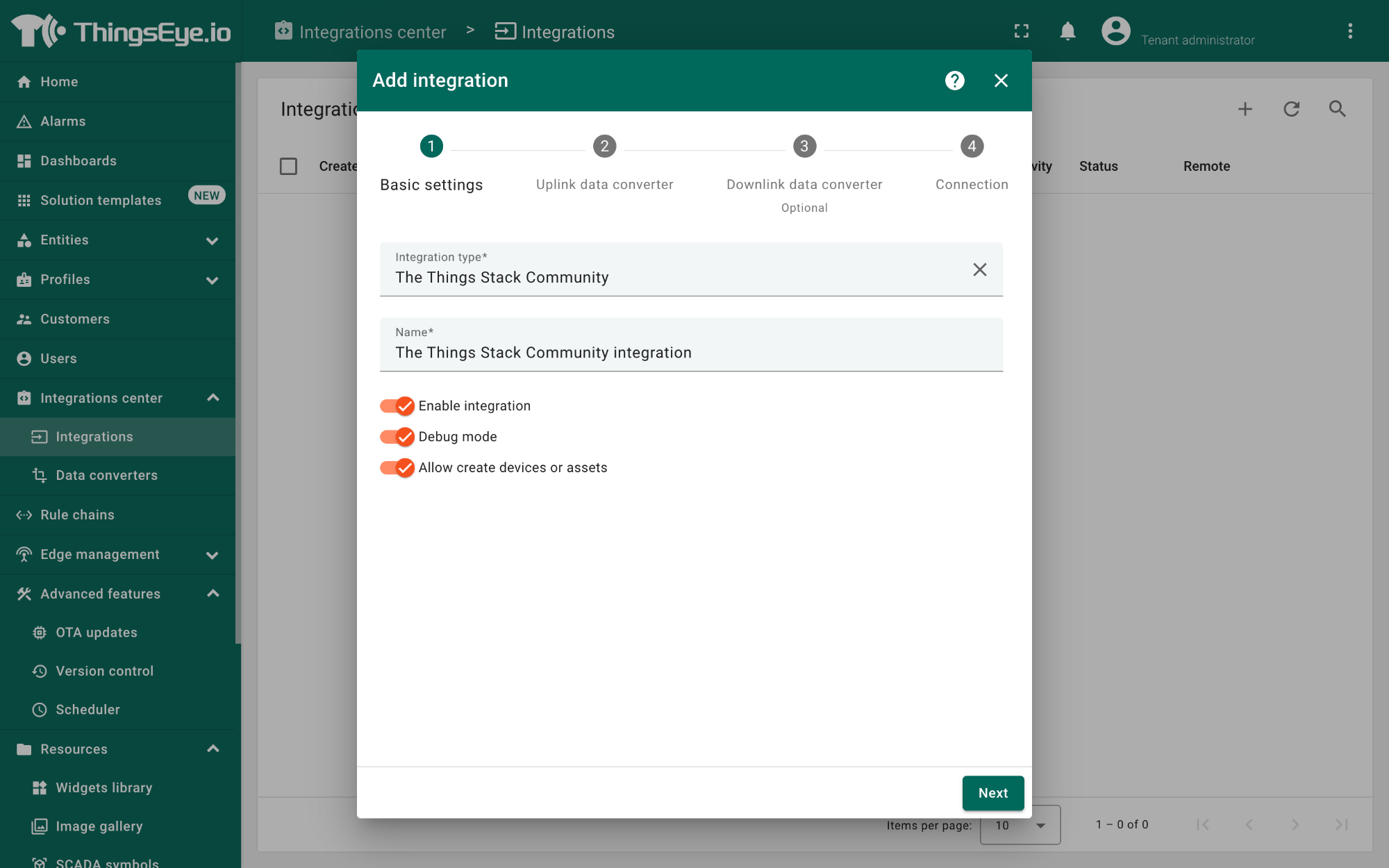
On the Add integration window, configure the following:
Basic settings:
- Select The Things Stack Community from the Integration type list.
- Enter a suitable name for your integration in the **Name text **box or keep the default name.
- Ensure the following options are turned on.
- Enable integration
- Debug mode
- Allow create devices or assets
- Click the Next button. you will be navigated to the Uplink data converter tab.
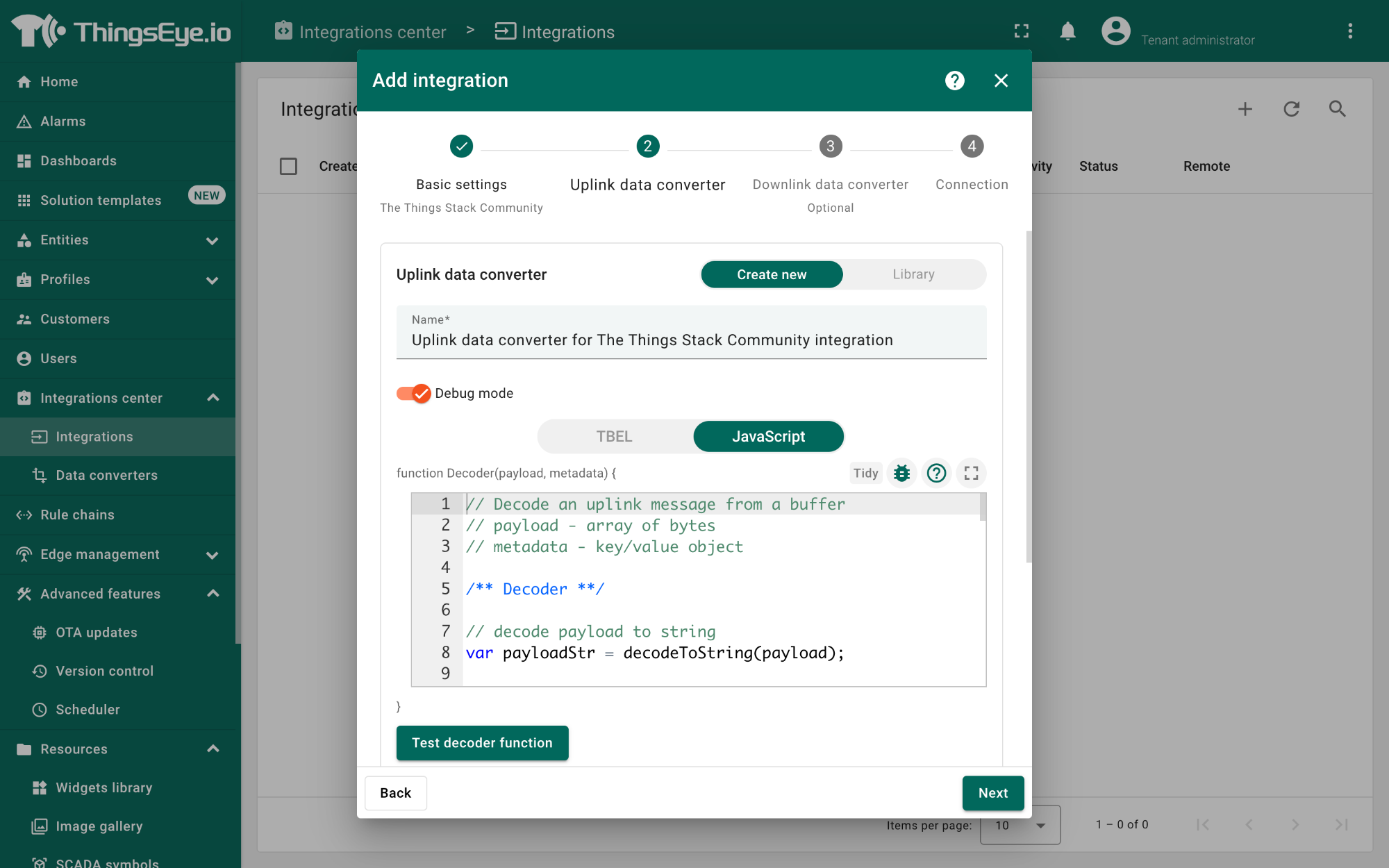
Uplink data converter:
- Click the Create new button if it is not selected by default.
- Enter a suitable name for the uplink data converter in the **Name text **box or keep the default name.
- Click the JavaScript button.
- Paste the uplink decoder function into the text area (first, delete the default code). The demo uplink decoder function can be found here.
- Click the Next button. You will be navigated to the **Downlink data converter **tab.
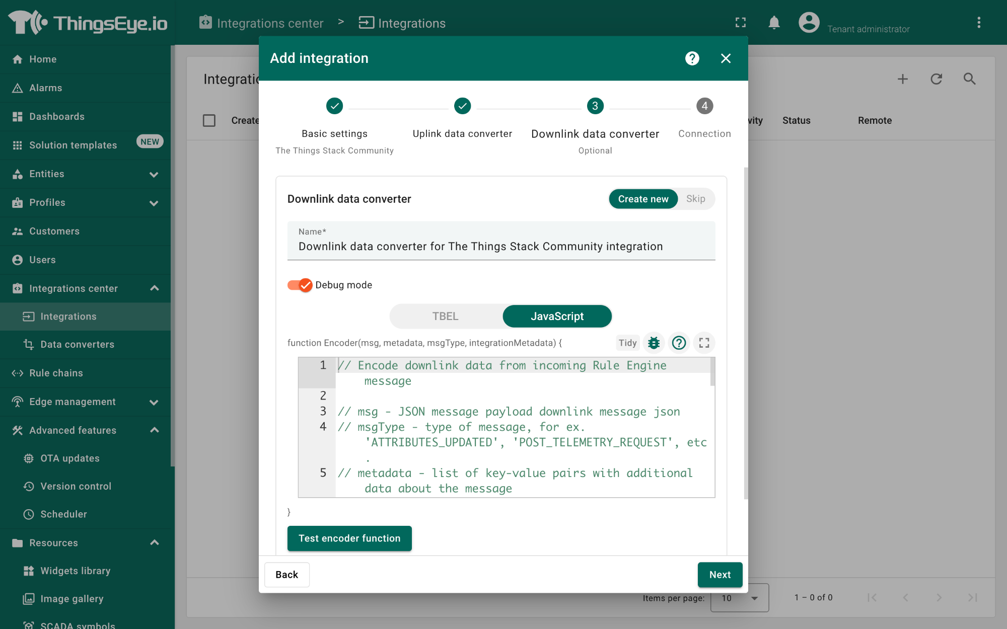
Downlink data converter (this is an optional step):
- Click the Create new button if it is not selected by default.
- Enter a suitable name for the downlink data converter in the **Name text **box or keep the default name.
- Click the JavaScript button.
- Paste the downlink decoder function into the text area (first, delete the default code). The demo downlink decoder function can be found here.
- Click the Next button. You will be navigated to the Connection tab.
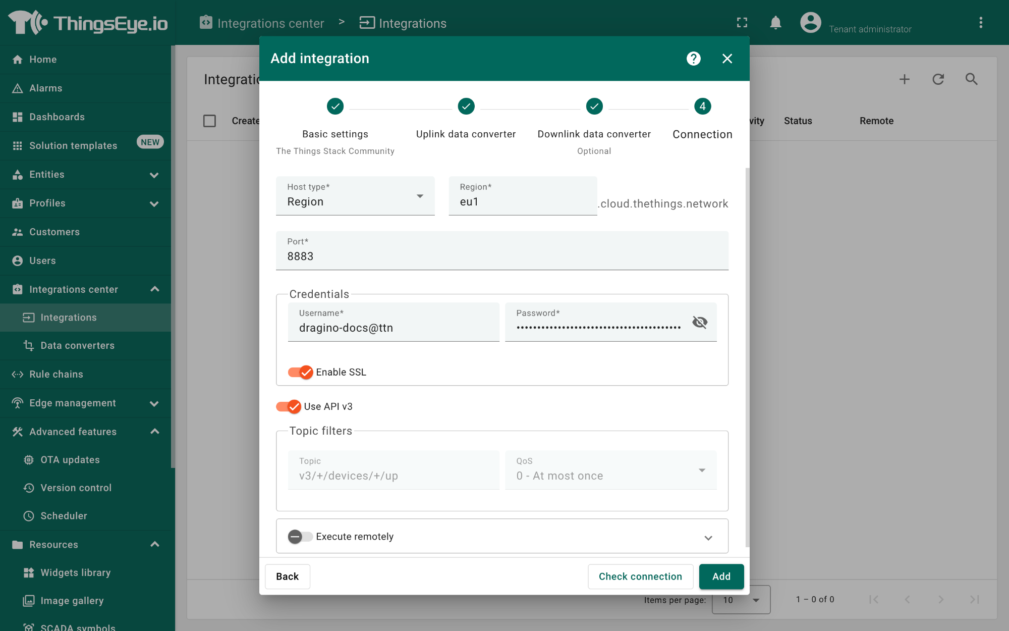
Connection:
- Choose Region from the Host type.
- Enter the cluster of your The Things Stack in the Region textbox. You can find the cluster in the url (e.g., https://eu1.cloud.thethings.network/...).
- Enter the Username and Password of the MQTT integration in the Credentials section. The **username **and **password **can be found on the MQTT integration page of your The Things Stack account (see 2.5.1.1 Configuring The Things Stack).
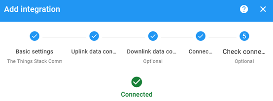
- Click the Check connection button to test the connection. If the connection is successful, you will see the message saying Connected.
- Click the Add button.
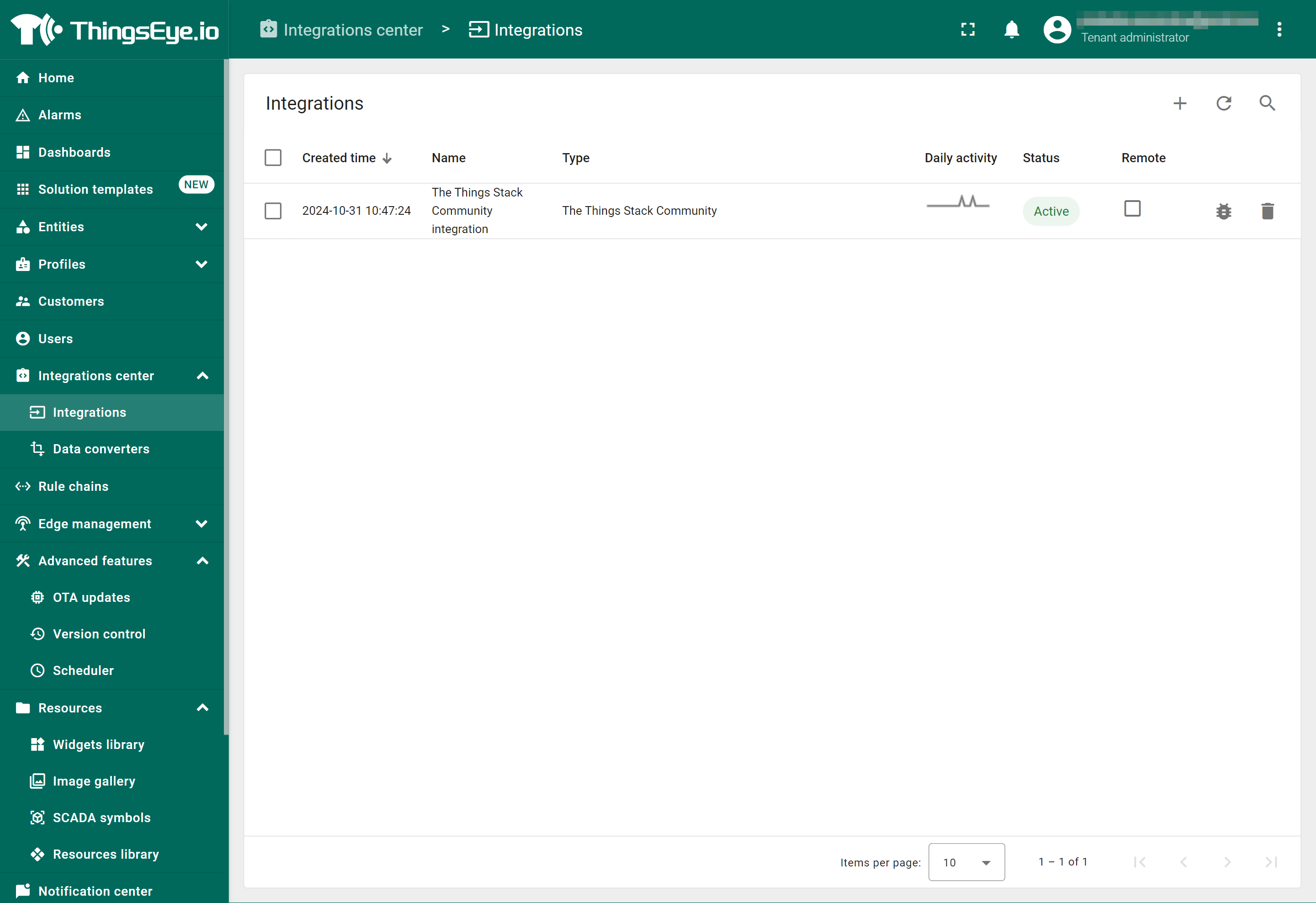
Your integration has been added to the** Integrations** list and will be displayed on the Integrations page. Check whether the status is shown as Active. If not, review your configuration settings and correct any errors.
2.5.1.3 Viewing integration details
Click on your integration from the list. The Integration details window will appear with the **Details **tab selected. The **Details **tab shows all the settings you have provided for this integration.
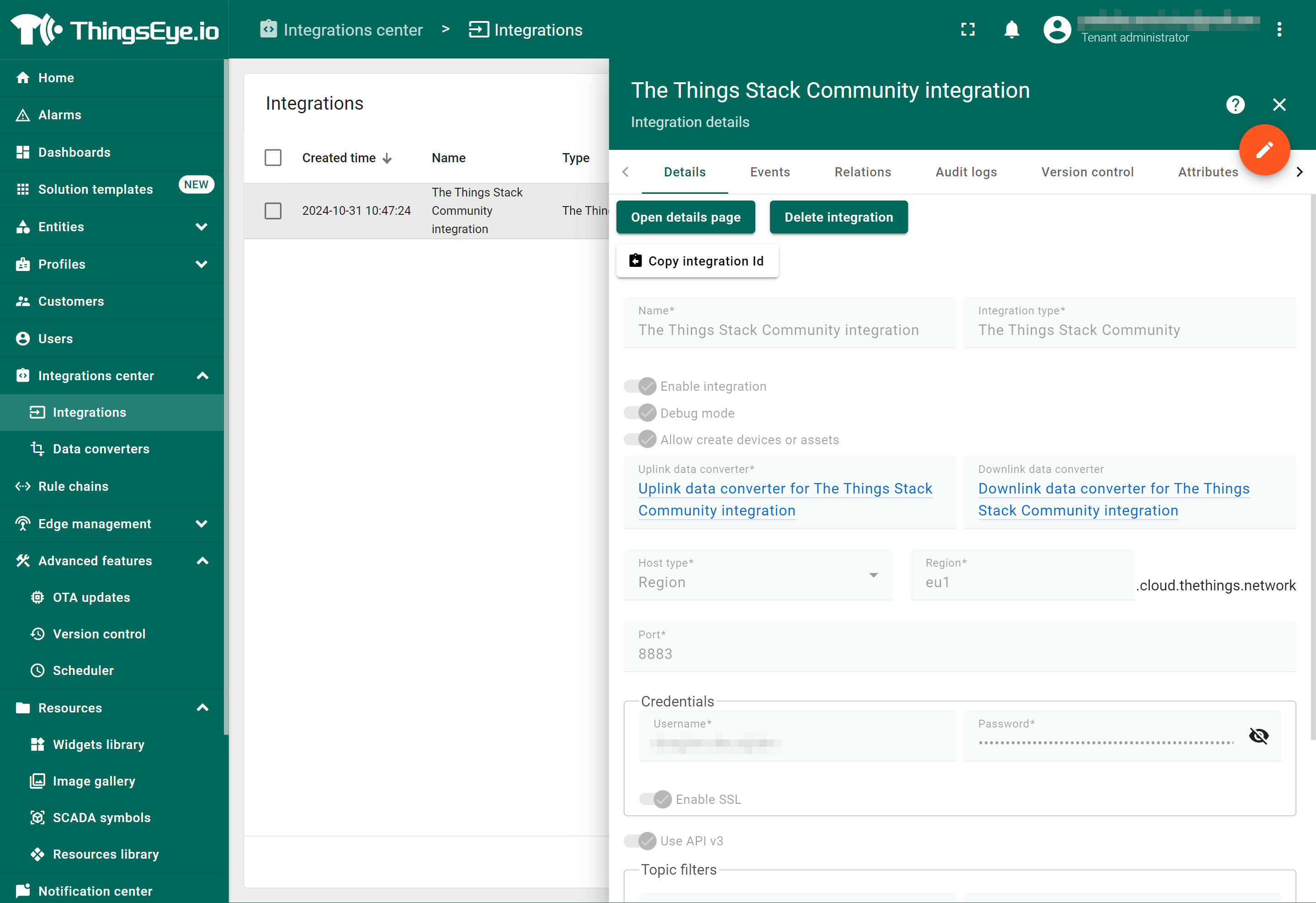
If you want to edit the settings you have provided, click on the Toggle edit mode button. Once you have done click on the **Apply changes **button.
Information
See also ThingsEye documentation.
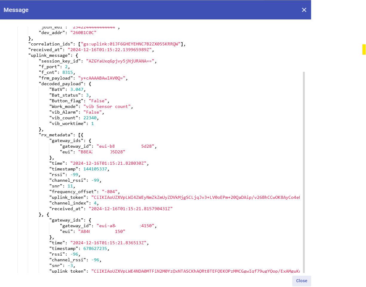
- To view the JSON payload of a message, click on the three dots (...) in the Message column of the desired message.
[add JSON payload screen capture here]
2.5.1.4 Viewing events
The **Events **tab displays all the uplink messages from the LHT65N-VIB.
- Select **Debug **from the Event type dropdown.
- Select the** time frame** from the time window.
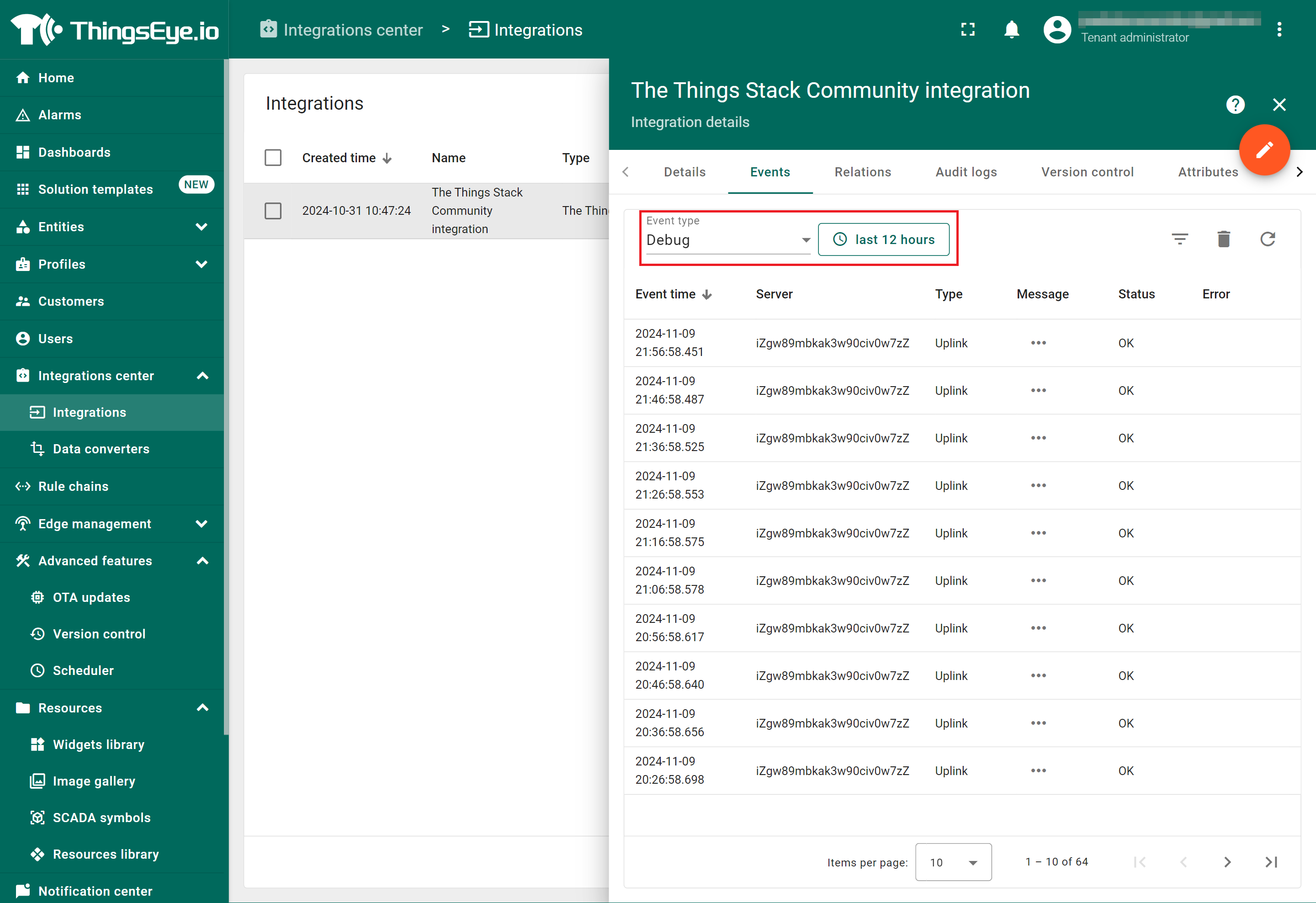
- To view the JSON payload of a message, click on the three dots (...) in the Message column of the desired message.
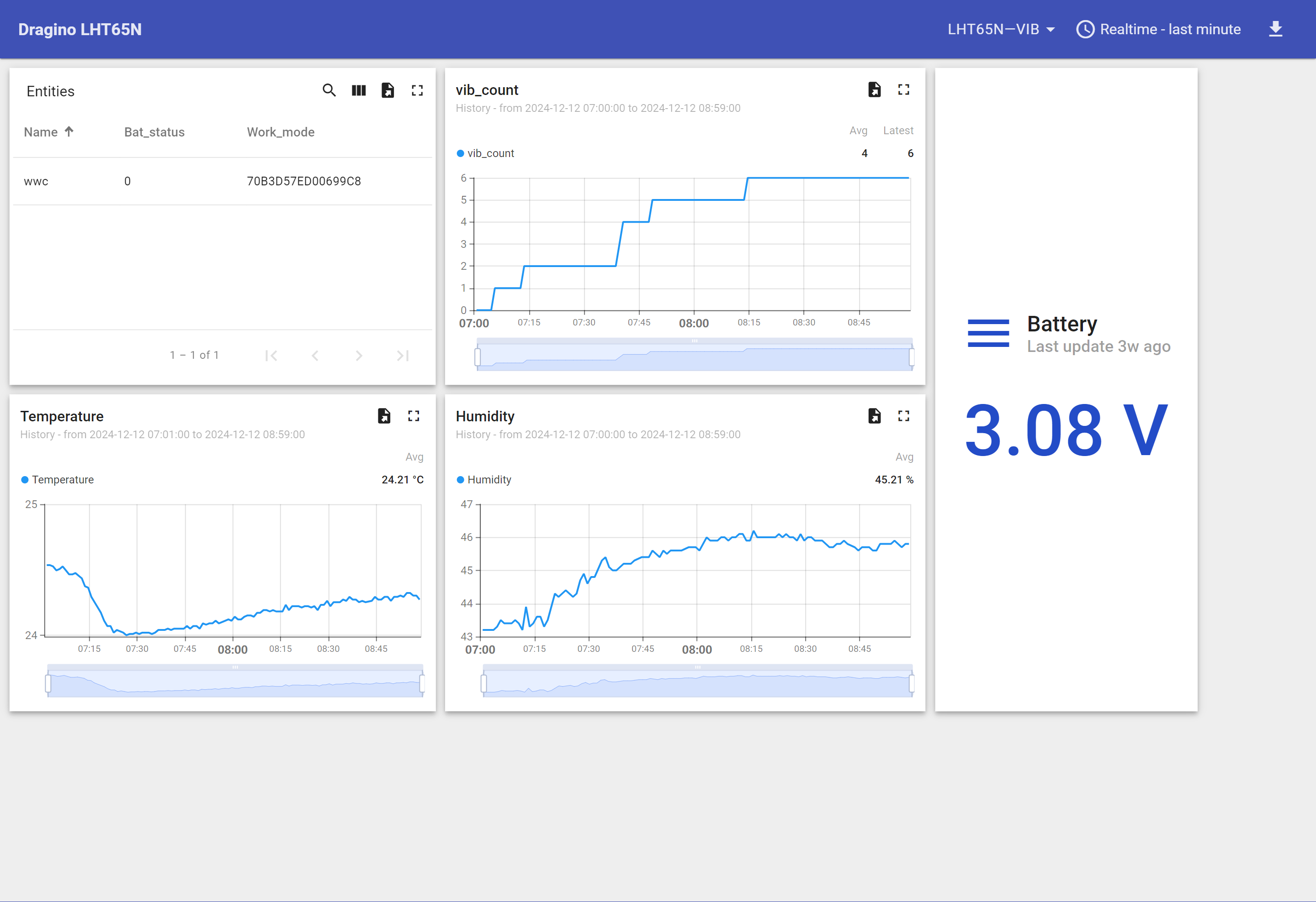
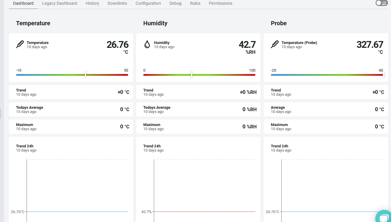
2.5.1.5 Viewing Sensor data on a dashboard
You can create a dashboard with ThingsEye to visualize the sensor data coming from the LHT65N-VIB. The following image shows a dashboard created for the LHT65N-VIB. See Creating a dashboard in ThingsEye documentation for more information.
2.5.1.6 Deleting an integration
If you want to delete an integration, click the Delete integration button on the Integrations page.
2.5.2 Integrate and show data on Datacake
The **Datacake **IoT platform provides a user-friendly interface to display sensor data. With this integration, once you receive the sensor data in The Things Stack application, you can send it to Datacake for further processing.
- Ensure that LHT65N-VIB is properly connected to The Things Stack.
Now configure your The Things Stack application to forward data to Datacake by adding an integration with webhooks.
- In The Things Stack console, navigate to Applications → <your application> → Integrations → Webhooks → + Add webhook.

- In the Choose webhook template page, select Datacake.

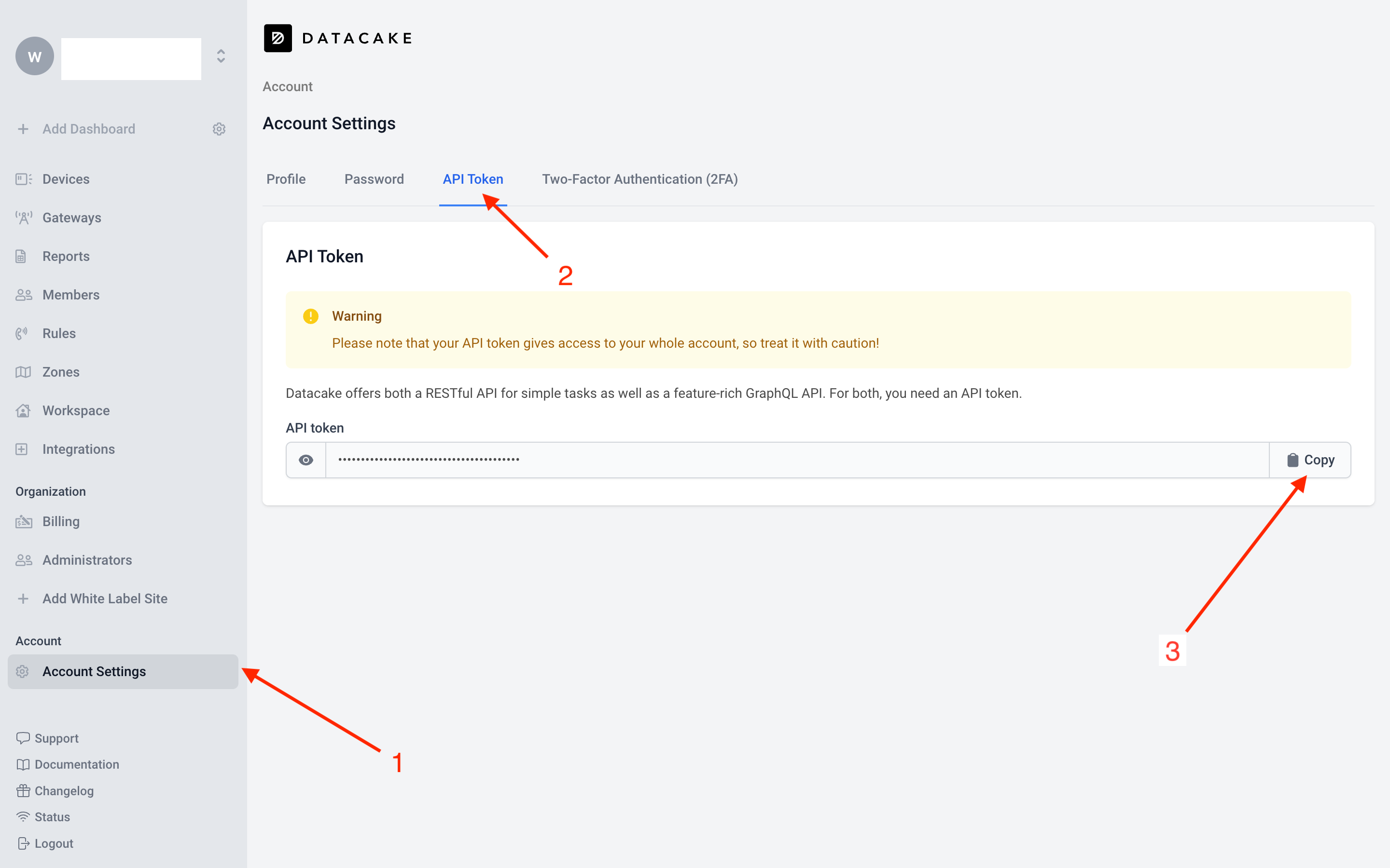
In Datacake, go to Account Settings, then navigate to the API Token tab. Click the Copy button to copy the API token.
On the Setup webhook for Datacake page, enter the Webhook ID and paste the Datacake API Token. Then select the Create Datacake webhook button.

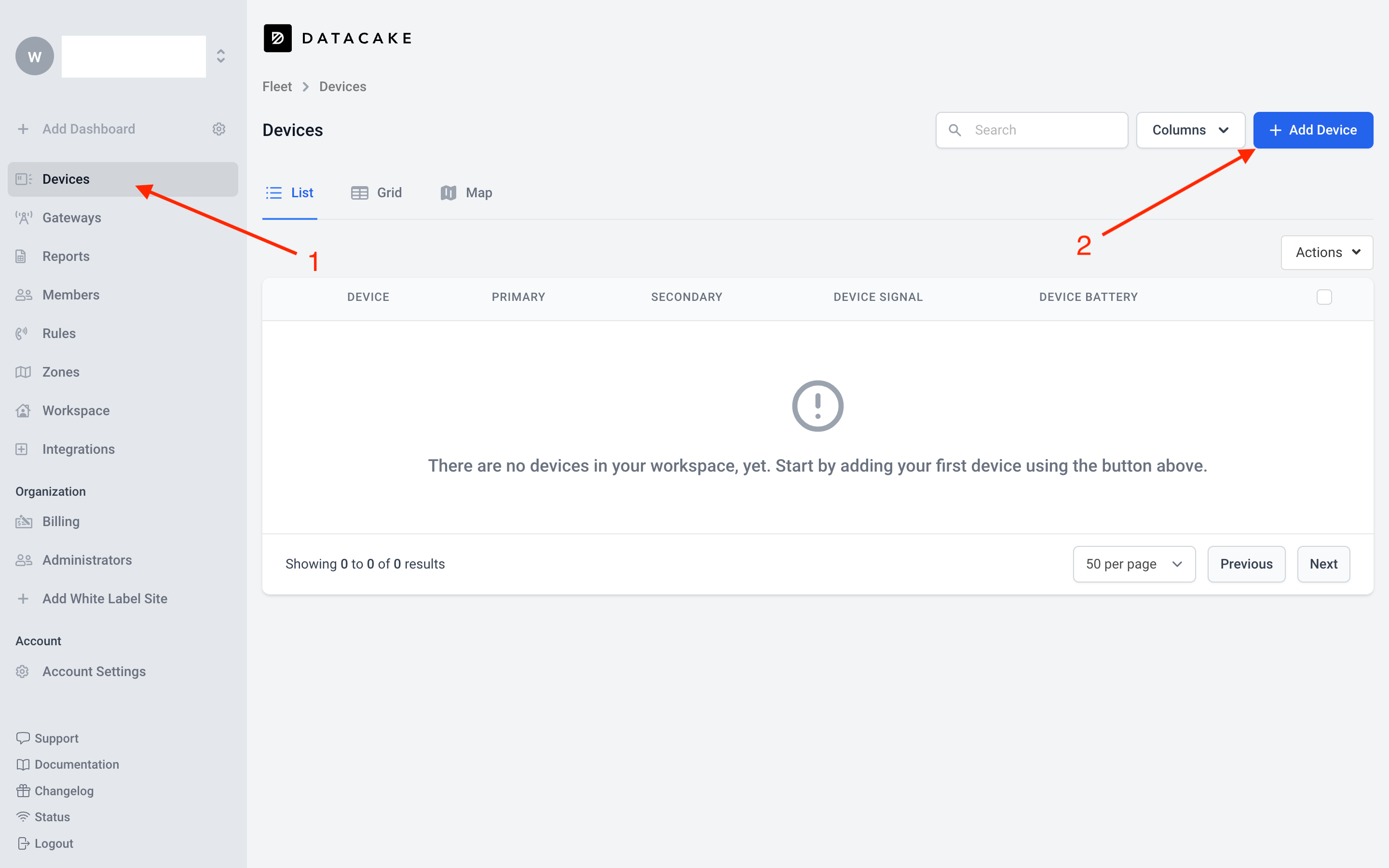
In the Datacake console (https://datacake.co/) , add LHT65N-VIB as follows.
1. On the left navigation, select Devices.
2. Click + Add Device button.
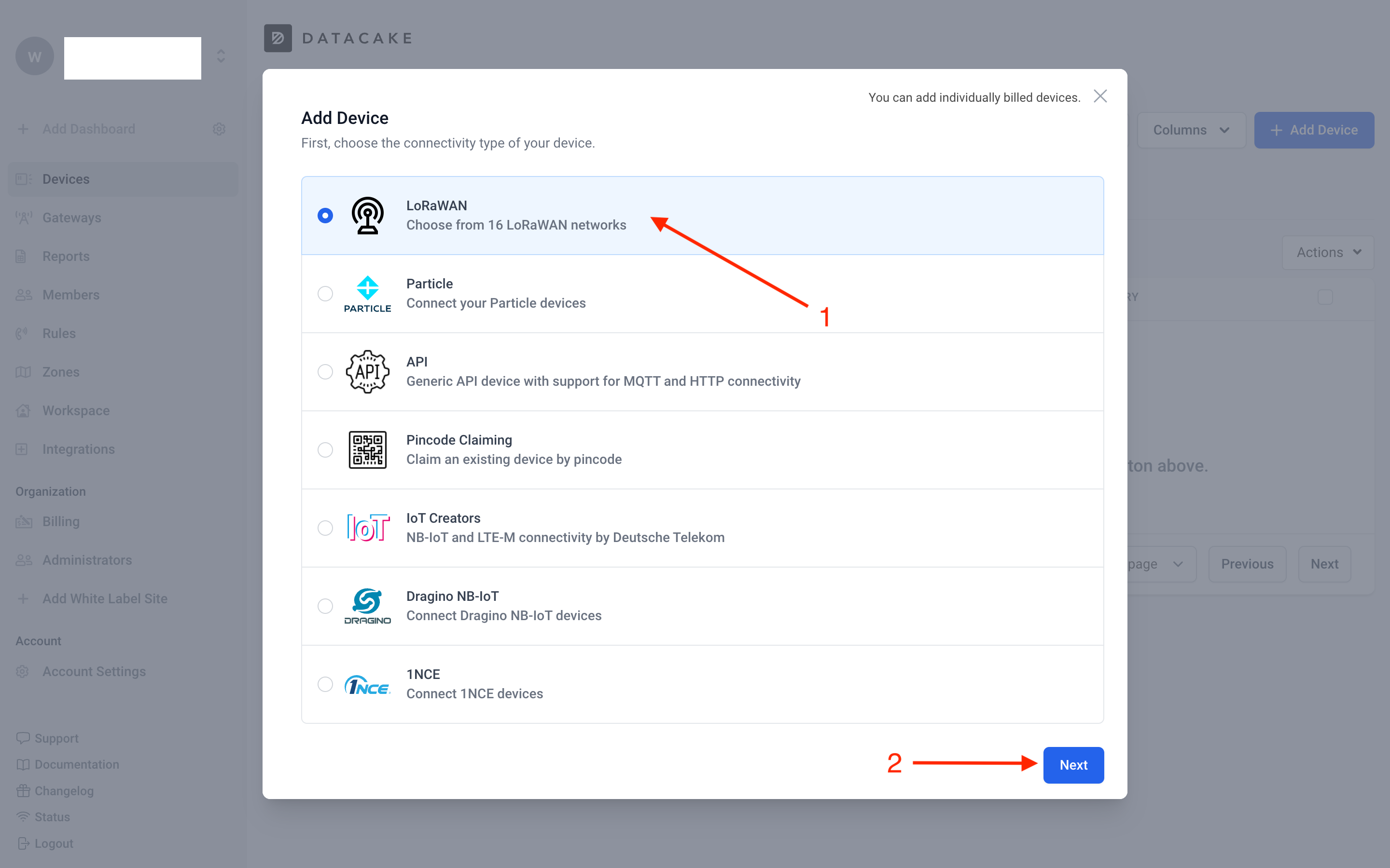
1. On the Add Device window, select the connectivity type of your device, in this case select LoRaWAN.
2. Click Next button.
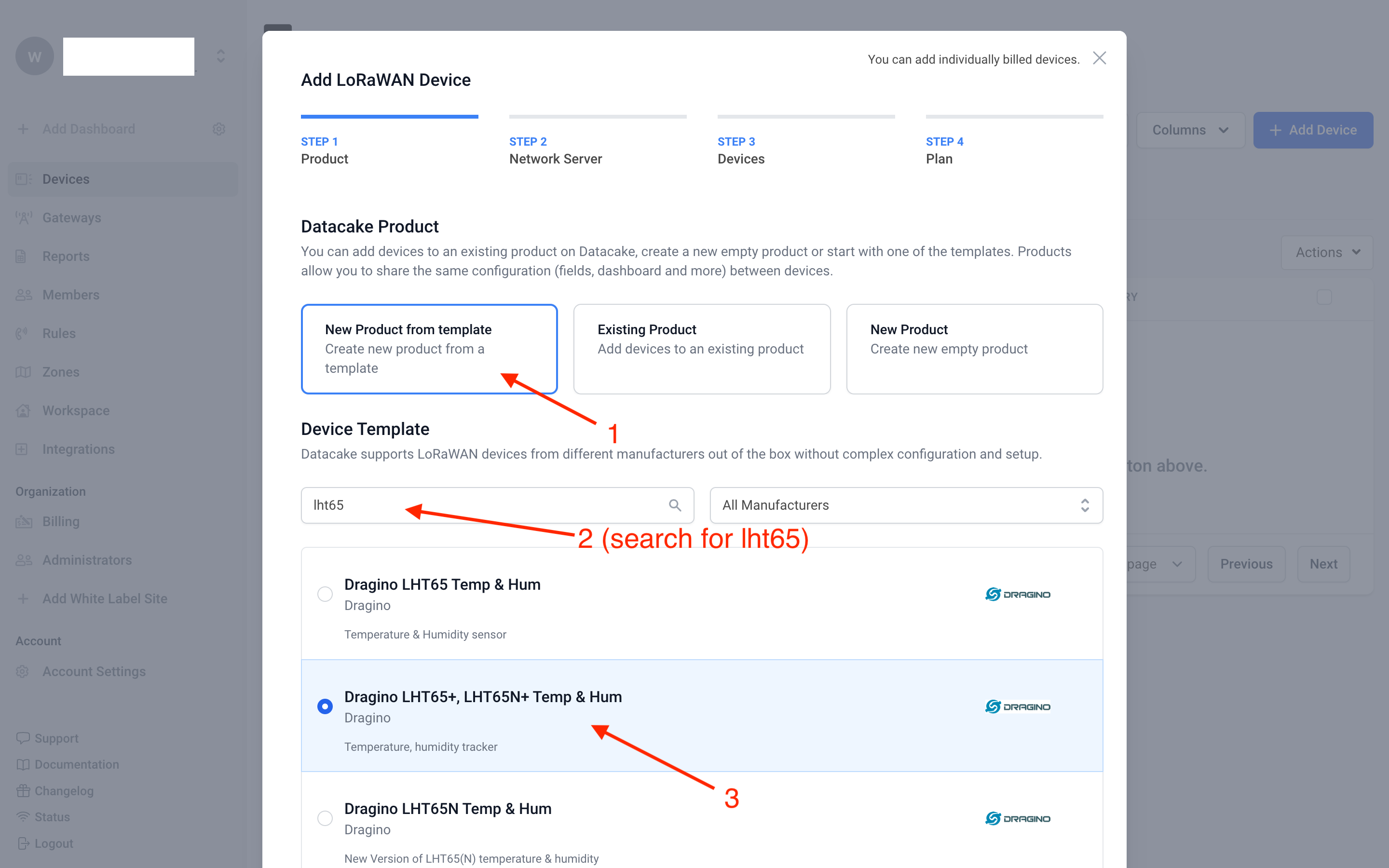
On the Add LoRaWAN Device window, under Product,
1. Select New Product from template.
2. Search for lht65
3. Select, **Dragino LHT65, LHT65N+ Temp & Hum **from the filtered list.
Click Next button.
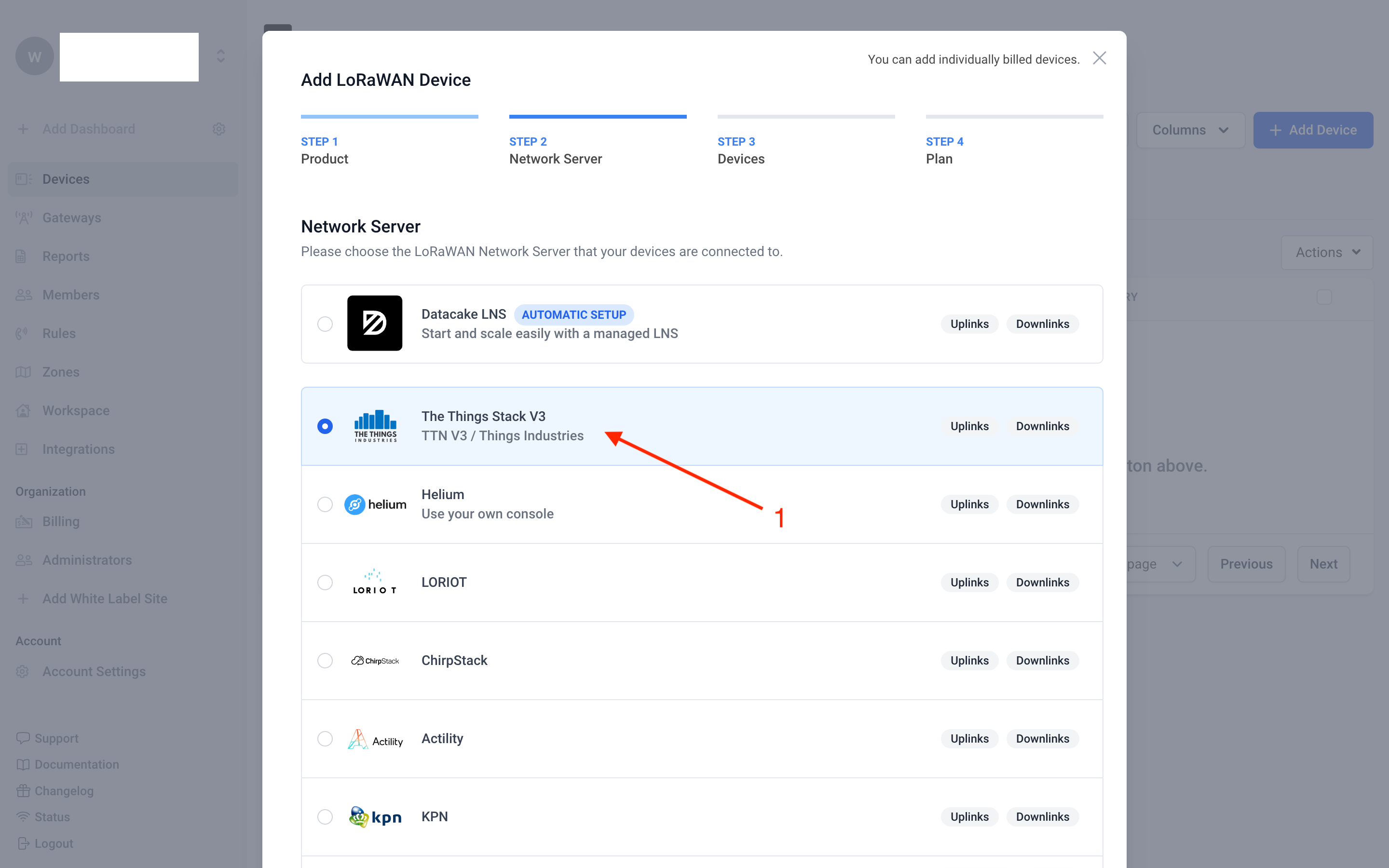
On the Add LoRaWAN Device window, under Network Server,
1. Select The Things Stack V3.
Click Next button.
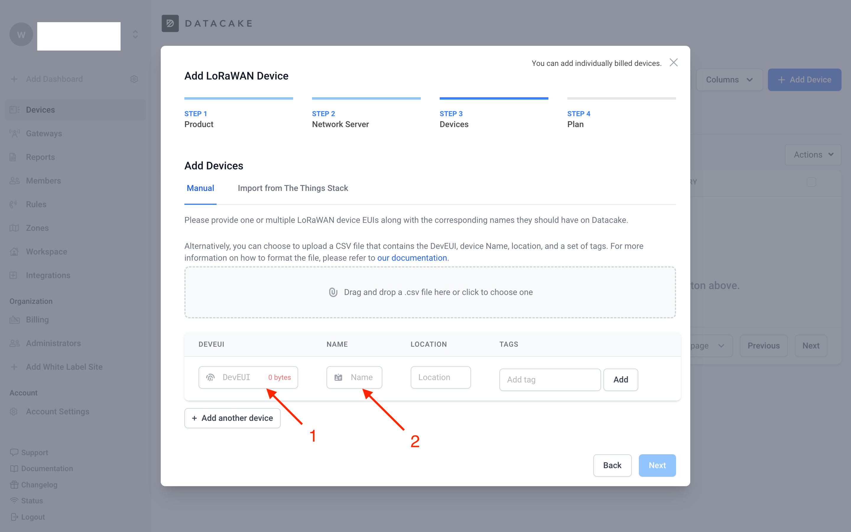
On the Add LoRaWAN Device window, under Devices,
1. Enter your LHT65N-VIB's DevEUI in the DevEUI field.
2. Assign a name for your device in the Name field.
Click Next button.
[will be continued... add more screenshots here]
2.8 LED Indicator
The LHT65N-VIB has a tri-color LED for easily indicating different stages.
When the user presses the ACT button, the LED will function according to the LED status linked to the ACT button.
In a normal working state:
- For each uplink, the BLUE or RED LED will blink once:
- BLUE LED: Indicates an external sensor is connected.
- RED LED: Indicates no external sensor is connected.
- For each successful downlink, the PURPLE LED will blink once.
2.9 Installation
This sections explains the assembling and installation instructions.
2.9.1 Attaching the vibration probe
The LHT65N-VIB is sold with an external vibration sensor probe. The vibration sensor probe can be connected to the LHT65N-VIB using its USB Type-C connector. You can find the USB Type-C port on the LHT65N-VIB after removing the blue plastic cap.
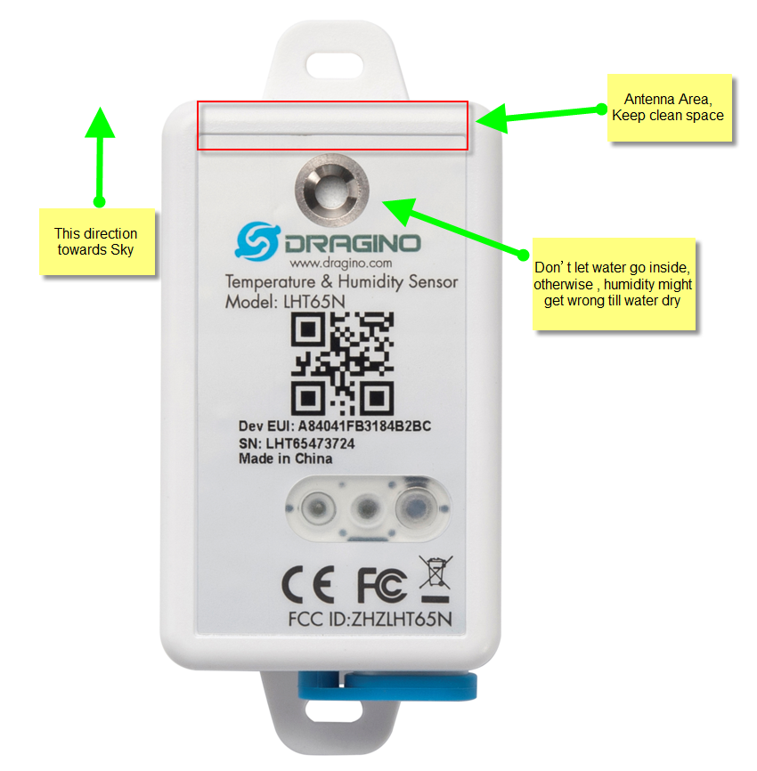
2.9.2 Installing on an object
The LHT65N should be installed vertically on objects, with the sensor parallel to the object's surface.
3. Configure the LHT65N-VIB via AT commands or LoRaWAN downlinks
You can configure the LHT65N-VIB via AT commands or LoRaWAN Downlinks.
Configure via AT Commands: See the FAQ for instructions on How to connect to the LHT65N-VIB's UART interface
LoRaWAN downlink instructions for different platforms: Refer to the IoT LoRaWAN Server
There are two kinds of commands to configure the LHT65N-VIB:
1. General Commands.
These commands are the same for all Dragino devices that support the DLWS-005 LoRaWAN Stack (Note**). You can find these commands on the wiki: End Device Downlink Command.
These commands can be used to configure:
-
General system settings, such as uplink interval.
-
LoRaWAN protocol and radio-related settings.
2. Commands design specially for the LHT65N-VIB
These commands are only valid for the LHT65N-VIB and are listed below:
3.1 Set Uplink Transmit Interval
Feature: Change the LHT65N-VIB's uplink transmission Interval.
AT command
| Command | AT+TDC |
| Parameters | time : time in milliseconds |
| Get | AT+TDC=? |
| Response | returns the current uplink interval |
| Set | AT+TDC=<time> |
| Response | <time> OK |
| Example | AT+TDC=60000 // Set uplink time interval to 60 seconds. |
Downlink command
| Prefix | 0x01 |
|---|---|
| Parameters | time : time in seconds - 3 bytes in hexadecimal |
| Payload format | <prefix><time> |
| Example |
|
3.2 Set Vibration Sensor Mode
Feature: Sets the Vibration Sensor Mode.
AT command
Note: In mode 1, mode 2, mode 3, the time unit is set in seconds, and in mode 4, the time unit is set in milliseconds.
There are four different working modes, and the uplink payload format varies for each mode:
- VIBMOD=1 : vib_count, work_min
- VIBMOD=2 : TempC_SHT, Hum_SHT, vib_count
- VIBMOD=3 : TempC_SHT, Hum_SHT, work_min
- VIBMOD=4 : X, Y, Z
| Command | AT+VIBMOD |
|---|---|
| Parameters | mode : 1, 2, 3, 4 alarm_time: Sets the duration of continuous operation required to trigger the alarm (unit: seconds). (Set AlarmTimeout to 65535 to disable the alarm.) - only applicable with mode 1, 2, 3 stop_duration_time: Specifies the interval after which the event is counted as a trigger. - only applicable with mode 1, 2, 3 **collection_interval **: Collection Interval (unit: seconds) - only applicable with mode 4. groups : Number of groups - only applicable with mode 4 |
| Set | for mode 1,2,3: AT+VIBMOD= for mode 4: AT+VIBMOD= |
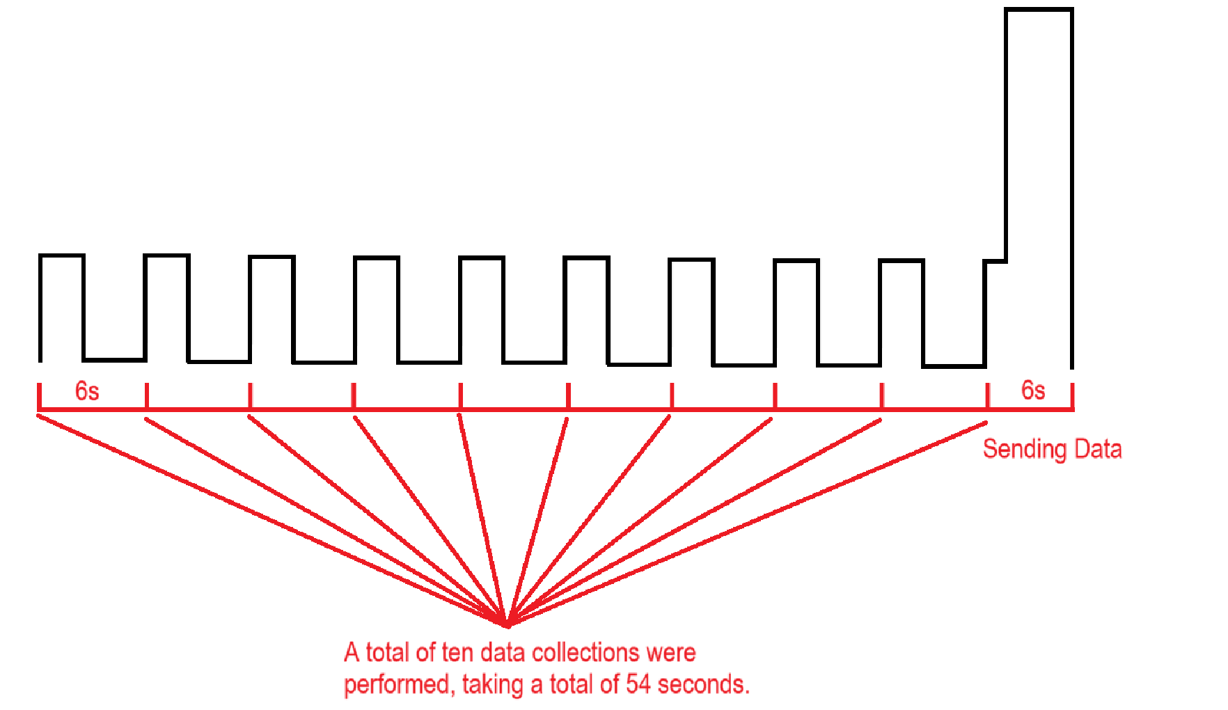
| Example | AT+VIBMOD=1,60,10****MOD1 will display vib_count and work_min without temperature and humidity. If vibration for more than 60 seconds, an alarm message is generated. If vibration stops for more than 10 seconds, vib_count increases by one, and work_min resets to zero. AT+VIBMOD=4,6000,10 MOD4 sets the collection interval to 6000 ms and collects 10 sets of data in total. |

If you want to calculate the acquisition time of each data, please refer to the current waveform diagram below. The following data is collected every 6 seconds, a total of 10 sets of data are collected, the acquisition time takes 54 seconds, and the data packet sending time takes 6 seconds, so the specific acquisition time of each data can be calculated.
Suppose you received the data packet at 12:15:30, then the first collection time is 12:14:30, and the second collection time is 12:14:36
Downlink command
| Prefix | 0x0A |
|---|---|
| Parameters | mode : 1, 2, 3, 4 [1 byte in hex] alarm_time: Sets the duration of continuous operation required to trigger the alarm (unit: seconds). (Set AlarmTimeout to 0 to disable the alarm.) - only applicable with mode 1, 2, and 3 [2 byte in hex] stop_duration_time: Specifies the interval after which the event is counted as a trigger. - only applicable with mode 1, 2, and 3 [2 bytes in hex] **collection_interval **: Collection Interval (unit: seconds) - only applicable with mode 4. [2 bytes in hexadecimal] groups : Number of groups - only applicable with mode 4. [2 bytes in hexadecimal] |
| Payload format | for mode 1, 2, 3: <prefix> for mode 4: <prefix> |
| Example |
|
3.3 Vibration sensitivity setting
Feature: Allows adjustment of sensitivity settings for different usage scenarios.
AT Command:
| Command | AT+VIBSET |
|---|---|
| Parameters | acceleration :
|
| Set | AT+VIBSET= |
| Response | OK |
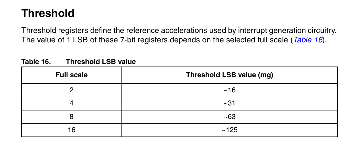
| Example | ** AT+VIBSET=0,4,10,12** The acceleration is set to ±2g and the frequency is 400 Hz. The threshold was set to 10 × 16 mg, meaning changes over 158 to 162 mg could be detected. |
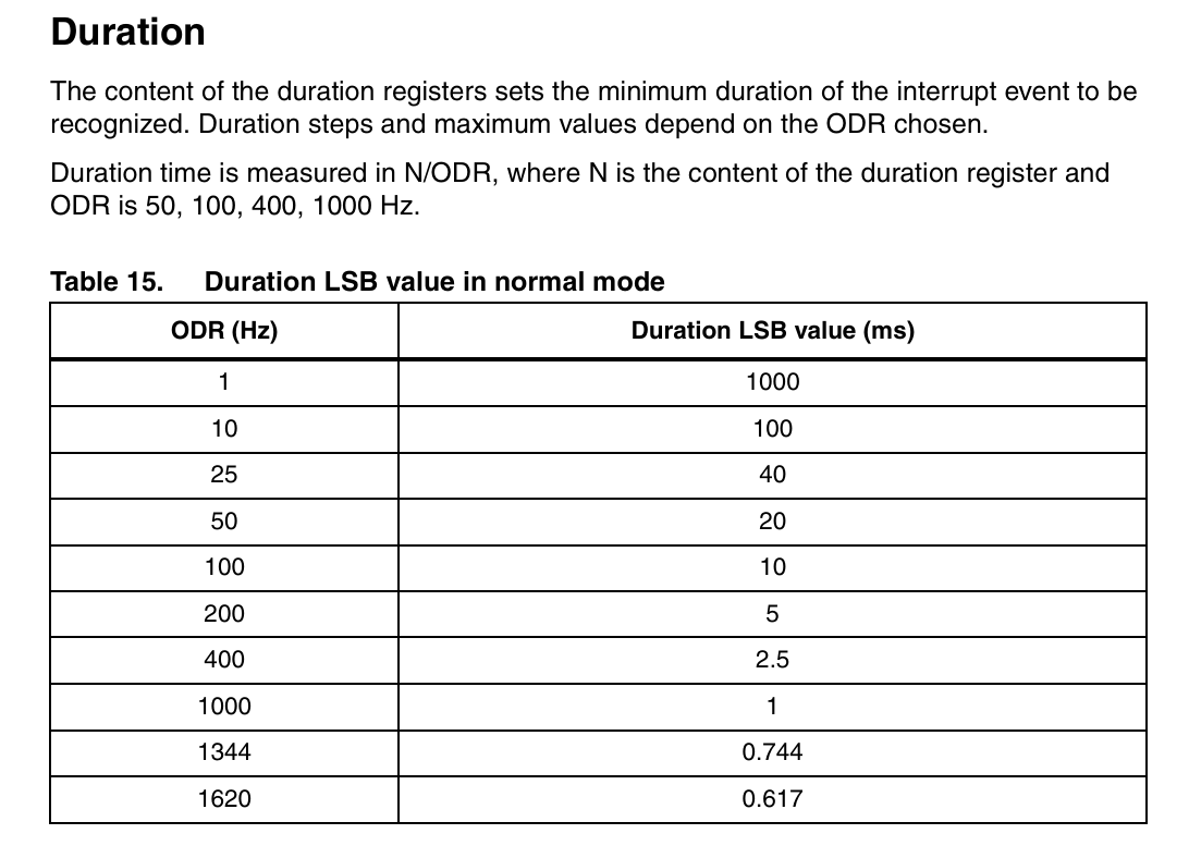
If you want to detect an event lasting at least 30 milliseconds, set the register to 30/2.5 = 12 counts. When the time difference between consecutive readings exceeds 12 duration LSBs, an interrupt will be triggered. See the figure below for specific values.
The following screenshots are taken from data sheets of the internal sensors:
Downlink Command
| Prefix | 0x09 |
|---|---|
| Parameters | acceleration : 2 bytes in hex
|
| Example | 0900040A0C The acceleration is set to ±2g and the frequency is 400 Hz. The threshold was set to 10 × 16 mg, meaning changes over 158 to 162 mg could be detected. |
3.4 Vibration MOD5 setting(Enabled in the latest version 1.3)
Feature: Data is monitored in real time over a period of time, and then the maximum acceleration value is uploaded.
AT Command:
| Command | AT+VIBMOD |
|---|---|
| Parameters | 1.mod: 5 2.odr: 1 – 9 default:9 Sensor activation frequency
|
| Set | AT+VIBMOD=mod, odr, scale, resolution, watermark, tdc |
| Response | OK |
| Example | AT+VIBMOD=5,9,0,0,20 |
Downlink Command
| Prefix | 0x0A |
|---|---|
| Parameters | 1.mod: 0X05 2.odr: 0x00-0x09 default:9 Sensor activation frequency
|
| Example | 0A 05 09 00 00 14 The acceleration is set to ±2g and the frequency is 400 Hz. The threshold was set to 10 × 16 mg, meaning changes over 158 to 162 mg could be detected. |
3.5 MOD5 Data Upload Time
Feature:Use in conjunction with MOD5 to adjust data upload timing.
AT Command:
| Command | AT+ULINTVL |
|---|---|
| Parameters | Second |
| Set | AT+ULINTVL=<time> |
| Response | OK |
| Example |
|
Downlink Command:
| Command | AT+ULINTVL |
|---|---|
| Parameters | Second |
| Set | AT+ULINTVL=<time> |
| Response | OK |
| Example |
|
3.6 Vibration MOD6 setting(Enabled in the latest version 1.4)
Feature: Data is monitored in real time over a period of time, and then the maximum acceleration value is uploaded.
AT Command:
| Command | AT+VIBMOD |
|---|---|
| Parameters | 1.mod: 6 2.odr: 1 – 9 default:9 Sensor activation frequency
|
| Set | AT+VIBMOD=mod, odr, scale, resolution, watermark, tdc |
| Response | OK |
| Example | AT+VIBMOD=6,9,0,0,20 |
Downlink Command
0X0A0609000014 //AT+VIBMOD=6,9,0,0,20
3.6 MOD6 Data Upload Time
Feature:Special packets used to maintain an active connection.
AT Command:
| Command | AT+KAINTVL |
|---|---|
| Parameters | Second |
| Set | AT+KAINTVL=<time> |
| Response | OK |
| Example |
|
Downlink Command:
| Command | AT+KAINTVL |
|---|---|
| Parameters | Second |
| Set | AT+KAINTVL=<time> |
| Response | OK |
| Example |
|
3.7 MOD6 Set Three-Axis Collision Detection Threshold
Feature:Set the detection thresholds for the X, Y, and Z axes. Please note that due to gravity, one of the axes will have an initial reading starting from 1g.
T Command:
| Command | AT+THLD |
|---|---|
| Parameters | 1.Axis:
|
| Set | AT+THLD=Axis,Starting, upper |
| Response | OK |
| Example | AT+THLD=1,0,1500 A data packet will be sent if the collision magnitude is less than 0 or greater than 1500 mg. |
Downlink Command:
| Command | AT+THLD |
|---|---|
| Parameters | mg |
| Set | AT+THLD=Axis,Starting, upper |
| Response | OK |
| Example | ** 0x4201000005DC //AT+THLD=1,0,1500** A data packet will be sent if the collision magnitude is less than 0 or greater than 1500 mg. |
3.8 MOD6 Set Axis Type, Low-Threshold Hysteresis Half-Width, High-Threshold Hysteresis Half-Width
Feature:Hysteresis prevents frequent state switches when the measured value fluctuates near threshold.
T Command:
| Command | AT+HYSHW |
|---|---|
| Parameters | 1.Axis:
|
| Set | AT+HYSHW=Axis,Starting, upper |
| Response | OK |
| Example | AT+THLD=1,0,1500 A data packet will be sent if the collision magnitude is less than 0 or greater than 1500 mg. |
Downlink Command:
| Command | AT+HYSHW |
|---|---|
| Parameters | mg |
| Set | AT+HYSHW=Axis,Starting, upper |
| Response | OK |
| Example | ** 0x430100000064 //AT+HYSHW=1,0,100** If you set AT+THLD=1,0,1500 and subsequently set AT+HYSHW=1,0,100, data will be uploaded only when the value falls below 1400 or rises above 1600. |
3.9 MOD6 Queue Capacity
Feature:
T Command:
| Command | AT+QCAP |
|---|---|
| Parameters | 1-7 |
| Set | AT+QCAP=5 |
| Response | OK |
| Example | AT+QCAP=5 To prevent upload congestion caused by multiple collisions, a default setting of 5 is sufficient. |
Downlink Command:
| Command | AT+QCAP |
|---|---|
| Parameters | 1-7 |
| Set | AT+QCAP=5 |
| Response | OK |
| Example | ** 0x440005 //AT+QCAP=5** To prevent upload congestion caused by multiple collisions, a default setting of 5 is sufficient. |
3.10 Set Password
Feature: Set device password, up to 9 digits
AT Command:
| Command | AT+PWORD |
|---|---|
| Parameters | password : any password |
| Get | AT+PWORD=? |
| Response | Returns the current password |
| Set | AT+PWORD= |
| Response | OK |
| Example |
|
Downlink Command:
There is no downlink command available for this feature.
3.11 Quit AT Command
Feature: Quit AT Command mode, so you need to input the password again before using AT Commands.
AT Command:
| Command | AT+DISAT |
| Parameters | none |
| Set | AT+DISAT |
| Response | OK |
| Example | AT+DISAT // quit AT command mode |
Downlink Command
There is no downlink command available for this feature.
3.12 Set to sleep mode
Feature: Set device to sleep mode.
AT Command:
| Command | AT+SLEEP |
|---|---|
| Parameters | mode : mode 0 : Normal working mode - The device enters sleep mode and uses lower power when there are no LoRa messages. 1 : Deep sleep mode -The device does not activate LoRa and is intended for storage or shipping. |
| Set | AT+SLEEP= |
| Response | OK |
| Example |
|
Downlink Command
There is no downlink command available for this feature.
3.13 Set system time
Feature: Set the system time.
AT Command:
| Command | AT+TIMESTAMP |
|---|---|
| Parameters | time : time in UNIX format. See here for format details. |
| Set | AT+TIMESTAMP=<time> |
| Response | OK |
| Example |
|
Downlink Command:
| Prefix | 0x30 |
|---|---|
| Parameters | time : time in UNIX format. See here for format details. - 5 bytes in hexadecimal |
| Example |
|
3.14 Set Time Sync Mode
Feature: Enable/Disable system time synchronization via the LoRaWAN MAC Command (DeviceTimeReq). The LoRaWAN server must support the v1.0.3 protocol to respond to this command.
AT Command:
| Command | AT+SYNCMOD |
|---|---|
| Parameters | time_sync_mode : Enable Sync system time via LoRaWAN MAC Command (DeviceTimeReq) 1 : enable (default) 0 : disable |
| Set | AT+SYNCMOD=<time_sync_mode> |
| Example |
|
| Note | If you want to set a different time than the LoRaWAN server, you need to set this to 0. |
Downlink Command:
| Prefix | 0x28 |
|---|---|
| Parameters | time_sync_mode : Enable Sync system time via LoRaWAN MAC Command (DeviceTimeReq) - 1 byte in hexadecimal 1 : enable (default) 0 : disable |
| Example |
|
3.15 Set Time Sync Interval
Feature: Define system time synchronization interval. The** **default value is 10 days.
AT Command:
| Command | AT+SYNCTDC |
|---|---|
| Parameters | sync_interval : synchronization interval |
| Set | AT+SYNCTDC=<sync_interval> |
| Response | |
| Example |
|
Downlink Command:
| Prefix | 0x29 |
|---|---|
| Parameters | sync_interval : synchronization interval - 1 byte in hexadecimal |
| Example |
|
3.16 Print data entries base on page
Feature: Print sensor data from start page to stop page (max is 416 pages).
AT Command:
| Command | AT+PDTA |
|---|---|
| Parameters | start : start page number end : end page number |
| Command format | AT+PDTA= |
| Example | AT+PDTA=1,3 // Prints sensor data from page 1 to 3 |
| Example response | Stop Tx events when read sensor data 8031000 2024/10/12 08:26:16 1 2807 tdc:yes alarm:false event_count:0 work_min:0 8031010 2024/10/12 08:26:40 1 2804 tdc:no alarm:false event_count:0 work_min:0 8031020 1970/1/1 00:00:10 1 2806 tdc:yes alarm:false event_count:0 work_min:0 8031030 2024/10/12 08:28:18 1 2805 tdc:yes alarm:false event_count:0 work_min:0 8031040 2024/10/12 08:29:18 1 2804 tdc:yes alarm:false event_count:0 work_min:0 8031050 2024/10/12 08:30:18 1 2806 tdc:yes alarm:false event_count:1 work_min:0 8031060 2024/10/12 08:30:27 1 2806 tdc:no alarm:true event_count:2 work_min:0 8031070 2024/10/12 08:31:18 1 2806 tdc:yes alarm:false event_count:3 work_min:1 [Rx][16:33:25.888] 8031080 2024/10/12 08:32:18 1 2806 tdc:yes alarm:false event_count:3 work_min:1 8031090 2024/10/12 08:33:18 1 2807 tdc:yes alarm:false event_count:3 work_min:1 80310A0 80310B0 80310C0 80310D0 80310E0 80310F0 8031100 8031110 8031120 8031130 8031140 8031150 8031160 8031170 Start Tx events OK |
Downlink Command:
There is no downlink command for this feature.
3.17 Print last few data entries
Feature: Print the last few data entries.
AT Command:
| Command | AT+PLDTA |
|---|---|
| Parameters | num_entries : number of data entries you want to print. |
| Command format | AT+PLDTA=<num_entries> |
| Example | AT+PLDTA=5 // Print last 5 entries |
| Example output | Stop Tx events when read sensor data 0001 2024/10/12 08:33:18 1 2807 tdc:yes alarm:false event_count:3 work_min:1 0002 2024/10/12 08:34:50 1 2808 tdc:yes alarm:false event_count:3 work_min:1 0003 2024/10/12 08:35:50 1 2808 tdc:yes alarm:false event_count:3 work_min:1 0004 2024/10/12 08:36:50 1 2809 tdc:yes alarm:false event_count:3 work_min:1 0005 2024/10/12 08:37:50 1 2810 tdc:yes alarm:false event_count:3 work_min:1 Start Tx and RTP events OK |
Downlink Command:
There is no downlink command for this feature.
3.18 Clear Flash Record
Feature: Clear the flash storage used by the data log feature.
AT Command:
| Command | AT+CLRDTA |
| Parameters | NO |
| Example | AT+CLRDTA // Clear all stored sensor data in the flash. |
Downlink Command:
| Prefix | 0xA3 |
| Parameters | 01 - always use 01 (hex) with the prefix |
| Example | A3 **01 **// Clear all stored sensor data in the flash. |
3.19 Auto Send None-ACK messages
Feature: LHT65N-VIB will wait for an ACK for each uplink. If LHT65N-VIB doesn't receive an ACK from the network server, it will assume the message didn't reach the server and store it. LHT65N-VIB continues sending messages periodically as usual. Once LHT65N-VIB receives an ACK from the network server, it will assume the network is functioning properly and start sending the messages that haven't arrived.
AT Command
The default factory setting is 0
| Command | AT+PNACKMD |
| Parameters | always 1 |
| Command format | AT+PNACKMD=1 // Polls non-ACK message |
| Response | OK |
Downlink Command
Prefix: 0x34
| Prefix | 0x34 |
| Parameters | 01 in hexadecimal |
| Payload format | 34**01 // **Polls non-ACK message |
3.20 Set Alarm Interval
Feature: Set the continuous alarm interval. If the vibration continues, you can set the continuous alarm state.
This is related to the settings of the last two parameters of your AT+VIBMOD command. This function needs to be used in conjunction with other commands.
AT Command:
| Command | AT+VIBALARM |
|---|---|
| Parameters | x: Set the alarm interval in minutes 0 : Call the police only once |
| Set | AT+VIBALARM=x |
| Example |
|
| Note | To set the continuous alarm time according to your needs, you need to use it with the parameters of AT+VIBMOD. |
Downlink Command:
| Prefix | 0x08 |
|---|---|
| Parameters | x: Set the alarm interval in minutes 0 : Call the police only once |
| Example |
|
4. Batteries
4.1 Battery Type
The LHT65N-VIB is equipped with a 2400mAh Li-MnO2 (CR17450) battery. The battery is non-rechargeable with a low discharge rate, designed for up to 8–10 years of use. This type of battery is commonly used in IoT devices for long-term operation, such as in water meters.
The discharge curve is nonlinear, so the battery level cannot be simply represented as a percentage. Below is the battery performance:
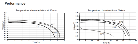
The minimum working voltage for the LHT65N-VIB is approximately 2.5V. When the battery voltage drops below 2.6V, it's time to replace the battery.
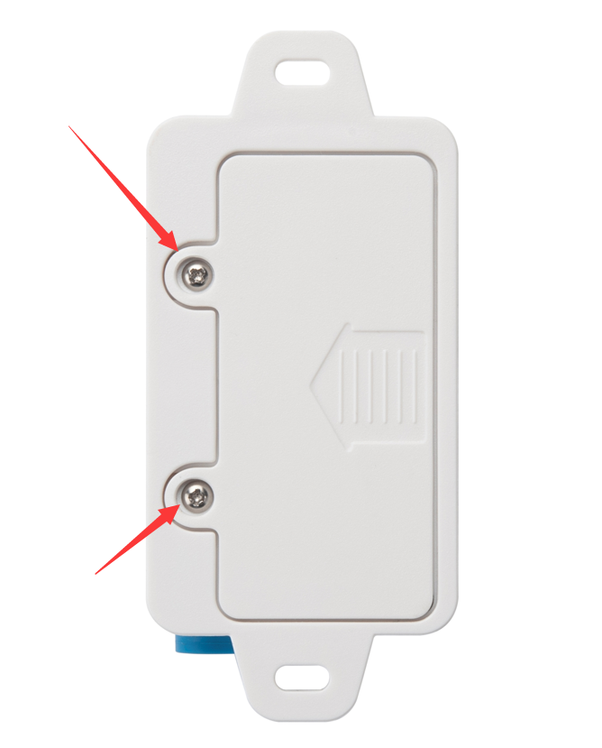
4.2 Replacing Batteries
The LHT65N-VIB has two screws on the back. Unscrew them to remove the battery cover and replace the battery inside. The sensor uses a standard CR17450 battery, and any brand should be suitable.

4.3 Battery Life Analysis
Dragino battery-powered products all operate in Low Power mode. You can refer to the guidelines from this link to calculate the estimated battery life: https://www.dropbox.com/scl/fo/kpnidyj98435yc2kzcuol/AGMEYy8T-ToxrjBxVKiBJMw?rlkey=clgoex1idnfka8845d6e9ajue&st=m513k45l&dl=0
A detailed test report for the LHT65N-VIB on different frequencies can be found here: https://www.dropbox.com/scl/fo/wnqaiyoq21kyzrmre6kzn/ABAgXYDr03OGSrM2ODFjUJA?rlkey=jed5yinvpdd0fiqww7x7cw201&st=rdtlz5ik&dl=0
5. FAQ
5.1 How to connect to LHT65N-VIB via UART interface?
The LHT65N-VIB has the UART interface in its Type-C. The UART Interface can be used for
- Send AT Commands, and get output from LHT65N-VIB
- Upgrade firmwre of LHT65N-VIB.
The hardware connection is: PC <--> USB to TTL Adapter <--> Jump wires <--> Type-C Adapter <--> LHT65N-VIB
5.1.1 Options for USB to TTL adapter
- CP2101 USB TTL Adapter
- CH340 USB TTL Adapter
- FT232 USB TTL Adapter
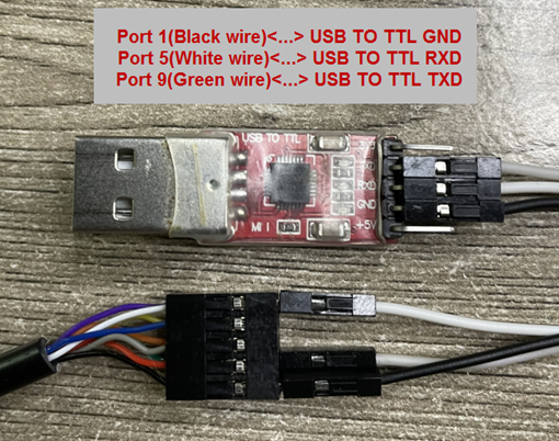
5.1.2 Options for Type-C adapter
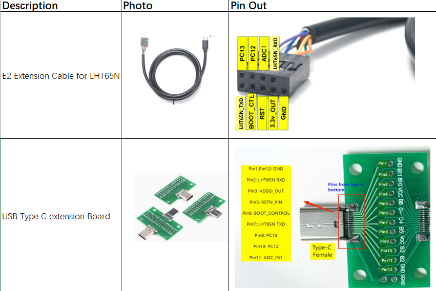
Connection:
- USB to TTL GND <--> LHT65N GND
- USB to TTL RXD <--> LHT65N TXD
- USB to TTL TXD <--> LHT65N RXD
5.1.3 Connection Example
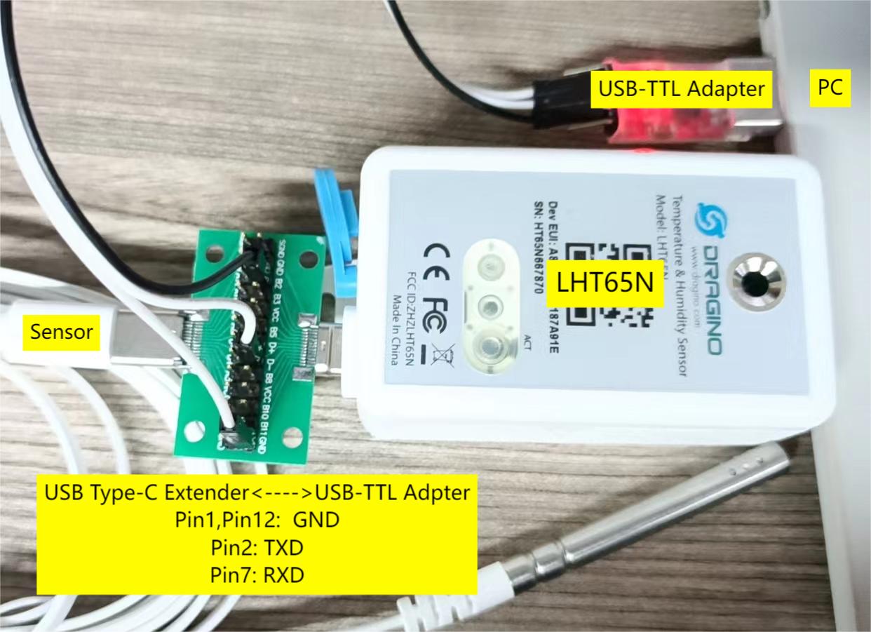
5.2 How to use AT commands?
First, connect the PC and LHT65N-VIB via USB TTL adapter as described in FAQ 6.1.
On the PC, you need to set serial tool (such as PuTTY or SecureCRT) baud rate to 9600 to access the serial console for LHT65N-VIB. The AT commands are disabled by default, and the user needs to enter the password (default: 123456) to activate them. The timeout for inputting AT commands is 5 minutes; after 5 minutes, the user will need to input the password again. The user can use the AT+DISAT command to disable AT commands before the timeout.
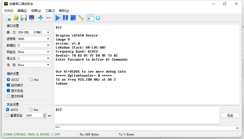
Input the password and ATZ to activate the LHT65N-VIB, as shown below:
5.2.1 AT commands
The AT command list is as below:
AT+<CMD>? : Help on <CMD>
AT+<CMD> : Run <CMD>
AT+<CMD>=<value> : Set the value
AT+<CMD>=? : Get the value
AT+DEBUG : Set more info output
ATZ : Triggers a reset of the MCU
AT+FDR : Reset Parameters to Factory Default, Keys Reserve
AT+DEUI : Get or Set the Device EUI
AT+DADDR : Get or Set the Device Address
AT+APPKEY : Get or Set the Application Key
AT+NWKSKEY : Get or Set the Network Session Key
AT+APPSKEY : Get or Set the Application Session Key
AT+APPEUI : Get or Set the Application EUI
AT+ADR : Get or Set the Adaptive Data Rate setting. (0: off, 1: on)
AT+TXP : Get or Set the Transmit Power (0-5, MAX:0, MIN:5, according to LoRaWAN Spec)
**AT+DR **: Get or Set the Data Rate. (0-7 corresponding to DR_X)
AT+DCS : Get or Set the ETSI Duty Cycle setting - 0=disable, 1=enable - Only for testing
AT+PNM : Get or Set the public network mode. (0: off, 1: on)
AT+RX2FQ : Get or Set the Rx2 window frequency
AT+RX2DR : Get or Set the Rx2 window data rate (0-7 corresponding to DR_X)
AT+RX1DL : Get or Set the delay between the end of the Tx and the Rx Window 1 in ms
AT+RX2DL : Get or Set the delay between the end of the Tx and the Rx Window 2 in ms
AT+JN1DL : Get or Set the Join Accept Delay between the end of the Tx and the Join Rx Window 1 in ms
AT+JN2DL : Get or Set the Join Accept Delay between the end of the Tx and the Join Rx Window 2 in ms
AT+NJM : Get or Set the Network Join Mode. (0: ABP, 1: OTAA)
AT+NWKID : Get or Set the Network ID
AT+FCU : Get or Set the Frame Counter Uplink
AT+FCD : Get or Set the Frame Counter Downlink
**AT+CLASS **: Get or Set the Device Class
**AT+JOIN **: Join network
AT+NJS : Get the join status
AT+SENDB : Send hexadecimal data along with the application port
AT+SEND : Send text data along with the application port
AT+RECVB : Print last received data in binary format (with hexadecimal values)
AT+RECV : Print last received data in raw format
AT+VER : Get current image version and Frequency Band
AT+CFM : Get or Set the confirmation mode (0-1)
AT+SNR : Get the SNR of the last received packet
AT+RSSI : Get the RSSI of the last received packet
AT+TDC : Get or set the application data transmission interval in ms
AT+PORT : Get or set the application port
AT+DISAT : Disable AT commands
AT+PWORD : Set password, max 9 digits
AT+CHS : Get or Set Frequency (Unit: Hz) for Single Channel Mode
AT+CHE : Get or Set eight channels mode,Only for US915,AU915,CN470
AT+PDTA : Print the sector data from start page to stop page
**AT+PLDTA **: Print the last few sets of data
**AT+CLRDTA **: Clear the storage, record position back to 1st
AT+SLEEP : Set sleep mode
**AT+BAT **: Get the current battery voltage in mV
AT+CFG : Print all configurations
AT+WMOD : Get or Set Work Mode
AT+ARTEMP : Get or set the internal Temperature sensor alarm range
AT+CITEMP : Get or set the internal Temperature sensor collection interval in min
AT+SETCNT : Set the count at present
AT+RJTDC : Get or set the ReJoin data transmission interval in min
AT+RPL : Get or set response level
AT+TIMESTAMP : Get or Set UNIX timestamp in second
AT+LEAPSEC : Get or Set Leap Second
AT+SYNCMOD : Get or Set time synchronization method
AT+SYNCTDC : Get or set time synchronization interval in day
AT+PID : Get or set the PID
5.3 How to use Downlink commands?
The following sections shows how to send downlinks to LHT65N-VIB from various LoRaWAN network servers.
5.3.1 The Things Stack
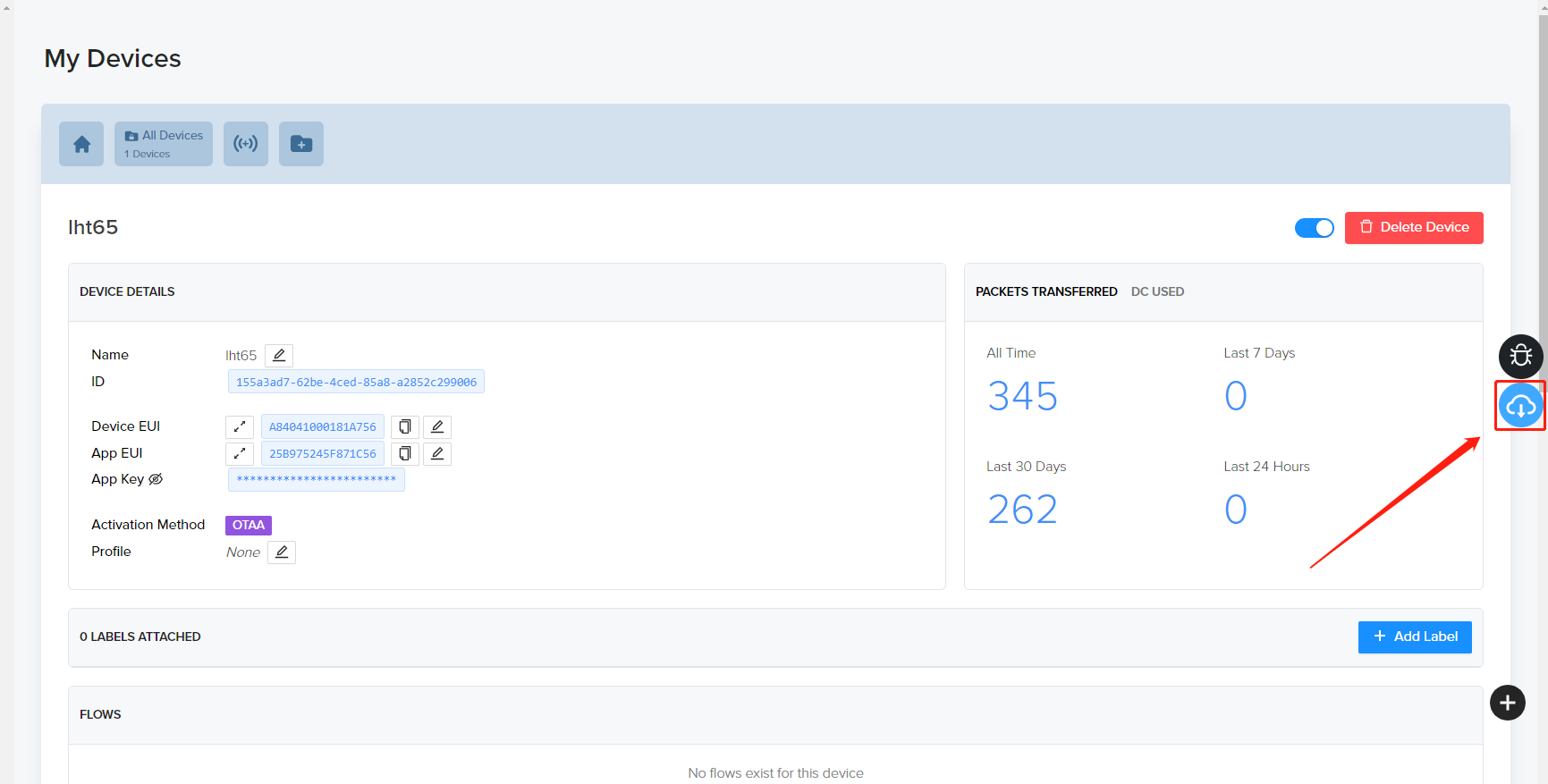
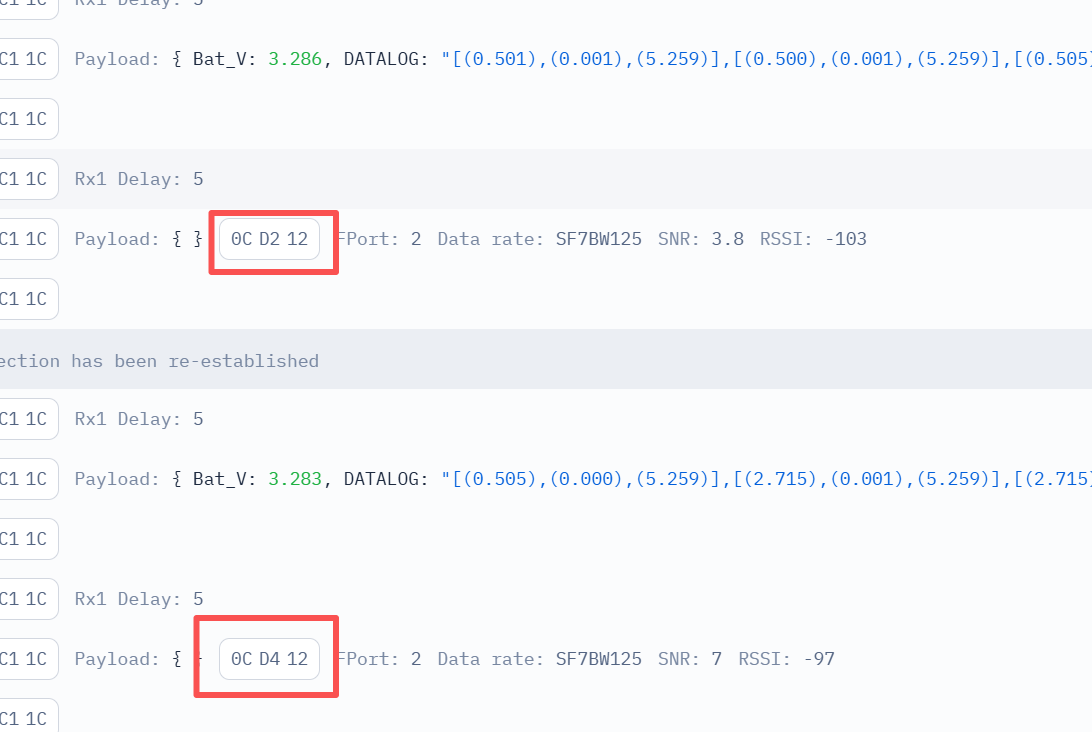
The following image shows how to send downlink commands (the payloads) from The Things Stack.

5.3.2 Helium
The following image shows how to send downlink commands (the payloads) from Helium.
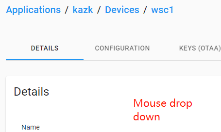
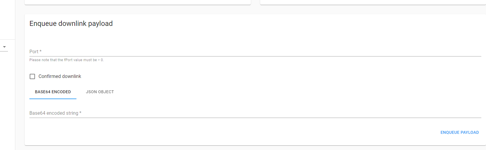
5.3.3 ChirpStack
The following image shows how to send downlink commands (the payloads) from ChripStack. The downlink window will not be displayed until the network is accessed.
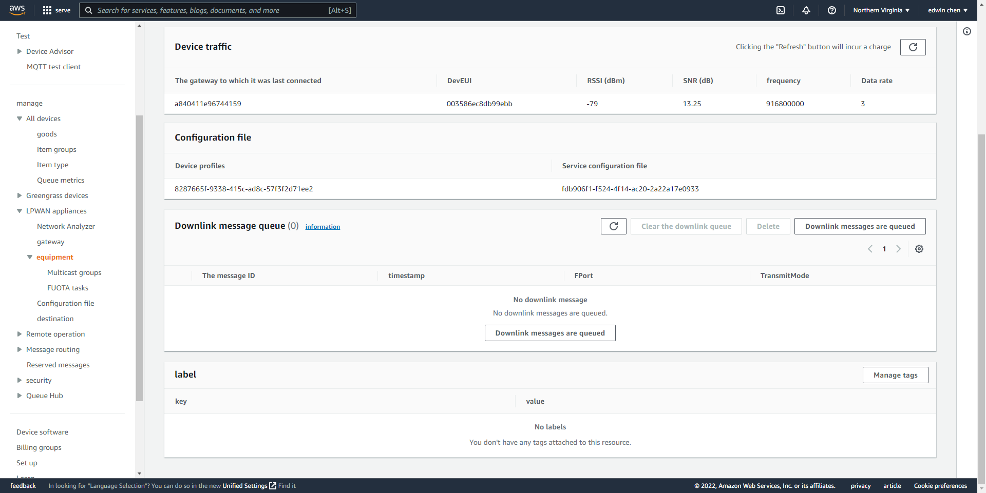
The following image shows how to send downlink commands (the payloads) from AWS-IOT.
5.3.4 AWS-IoT
5.4 How to change the uplink interval?
See the Sub section 3.1, Set Transmit Interval Time.
5.5 How to upgrade the firmware?
You can upgrade firmware of the LHT65N-VIB to:
- Change the frequency band/region.
- Add new features.
- Fix bugs.
The firmware and changelog can be downloaded from : Firmware download link
Methods to Update Firmware:
- Recommended method: OTA (Over-the-Air) firmware update via wireless. For instructions, visit: /docs/wiki/Configuration/end-node/lorawan-ota-firmware/
- Alternative Method: Update via UART TTL interface. For instructions, see: Update Instruction.
5.6 Why can't I see the datalog information?
1. The time is not aligned, and the correct query command was not used.
2. Decoder error: the datalog data was not parsed, and the data was filtered out.
5.7 How can I read sensor data without LoRaWAN? (for calibration purpose)
Some clients may need to calibrate sensor values in a lab environment. In these cases, it’s more convenient to read the data without a LoRaWAN network. To do this, you can use a USB Type-C breakout board to access the UART pins while keeping the probe connected. See below for details. For the pinout, please refer to the FAQ on How to connect LHT65-N via UART interface.
After the UART connection is established, run the commands below:
1.** AT+NJM=0 **// Set Device to ABP mode so it can work without joining the LoRaWAN network server.
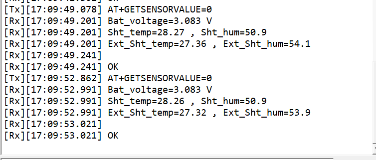
2.** AT+GETSENSORVALUE=0 **// The serial port gets the reading from the current sensor.
Example output:
5.8 Regarding the issue of MOD4 displaying 3 bytes.
The first two bytes represent the battery level, and the last byte indicates the MOD4 TDC flag and alarm flag.
If you don't want these 3 bytes to appear frequently, you can adjust the TDC time to be longer. Enter the command AT+TDC=1200000 (20 minutes).
6. Ordering Information
Part Number: ** LHT65N-VIB-XX**
**XX **: The default frequency band
- ** AS923**: LoRaWAN AS923 band
- ** AU915**: LoRaWAN AU915 band
- ** EU433**: LoRaWAN EU433 band
- ** EU868**: LoRaWAN EU868 band
- ** KR920**: LoRaWAN KR920 band
- ** US915**: LoRaWAN US915 band
- ** IN865**: LoRaWAN IN865 band
- ** CN470**: LoRaWAN CN470 band
7. Packing Information
The package includes:
- LHT65N-VIB LoRaWAN Vibration Sensor x 1
- External vibration probe x 1
8. Reference Materials
9. FCC Warning
This device complies with Part 15 of the FCC Rules. Operation is subject to the following two conditions:
- This device may not cause harmful interference.
- This device must accept any interference received, including interference that may cause undesired operation.
10. Use Cases
This section includes some example practical applications for the LHT65N-VIB.
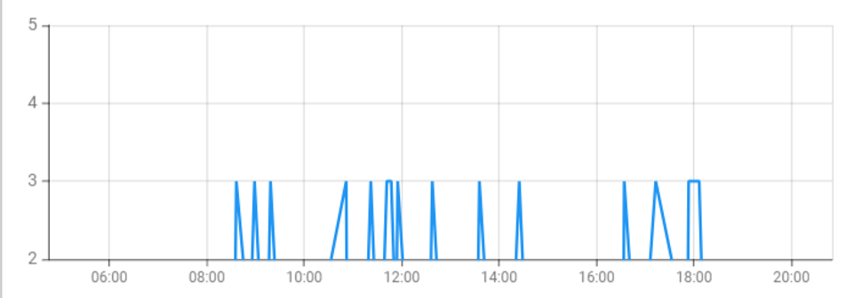
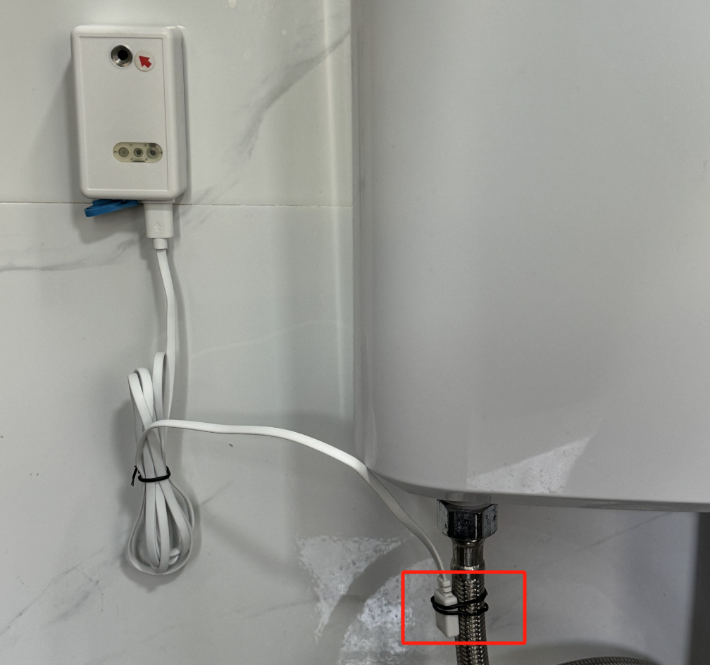
10.1 Install the LHT65N-VIB to monitor the usage of handwashing stations
Device settings using AT command: AT+VIBMOD=1,120,5
This means that if the water faucet remains on, a vibration lasting more than 120 seconds will trigger an alarm. When the vibration stops for more than 5 seconds, the vibration count will increase by 1.
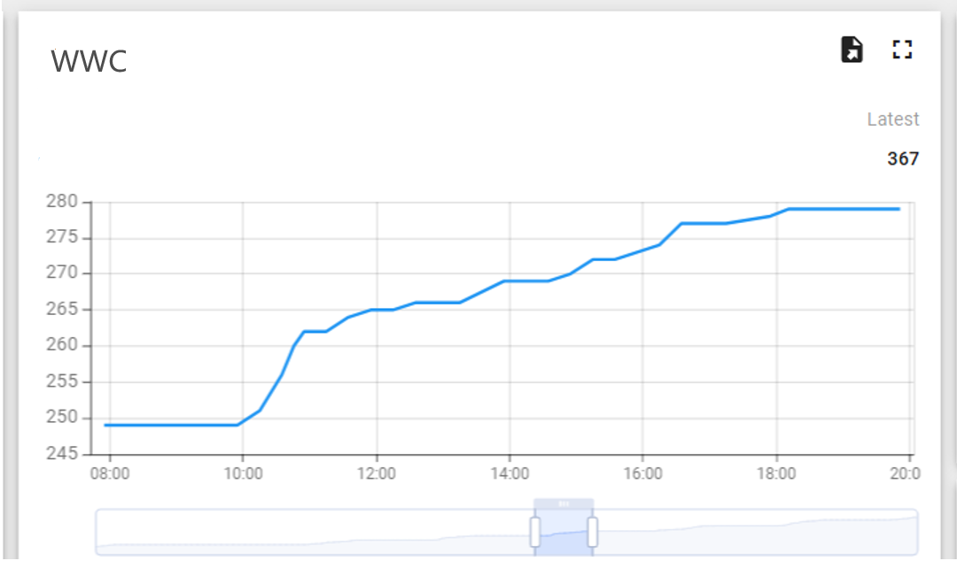
- The data begins to rise after 8 o'clock, indicating that the wash basin sensor is working normally.
- During lunch time, from 12 noon to 1:30 PM, the data temporarily levels off but returns to normal operation after.
- At 6 PM, after work hours, the data flattens out, with only a small amount recorded, caused by employees working overtime and using the wash basin.
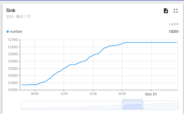
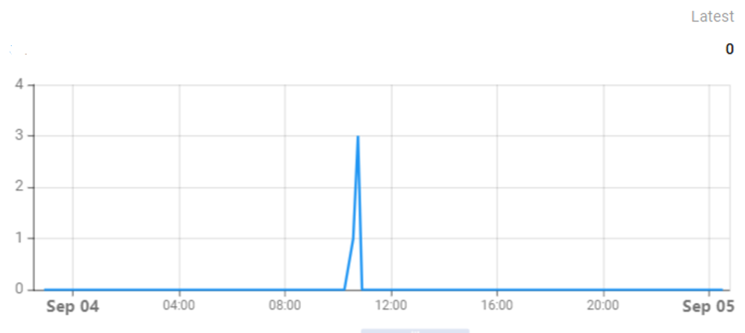
- Number of wash basin alarms: 14 times
- The rest period is concentrated around 12 o'clock, as people wash their hands during the lunch break.
- The longer duration at 6 o'clock is due to someone needing to turn on the water to clean the toilet.
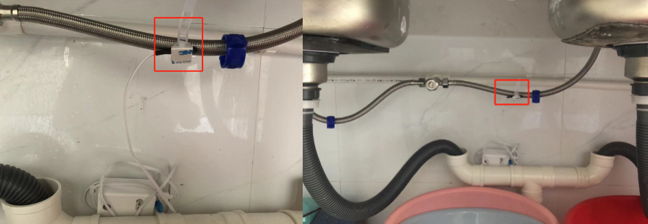
Sink installation example: Fix the probe to the water inlet pipe of the sink using a cable tie. Since the vibration in the middle is not as noticeable, and the water outlet on the right is larger than the one on the left, resulting in a larger vibration amplitude, the probe should be installed at the middle of the left water inlet pipe. This way, vibrations can be detected on both sides of the water pipe.
The following figure illustrates this use case from the network point of view.

10.2 Install LHT65N-VIB on the toilet water pipe to detect the number of times it is used and the leakage status
Toilet installation example: Fix the probe to the water inlet pipe of the toilet with a wire tie. When the toilet is used, the pipes began to fill with water and vibrate, and the LHT65N-VIB will start detecting vibrations in the water pipe.
Note: LHT65N-VIB should not be immersed in water. If necessary, ensure it is waterproofed.
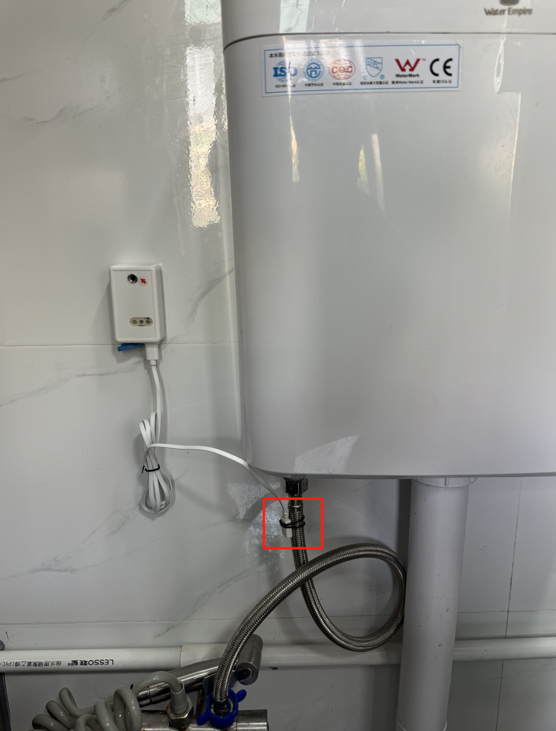
Device settings using AT command: AT+VIBMOD=1,150,5
This means that if the vibration exceeds 150 seconds, an alarm message will be issued. When the vibration stops for more than 5 seconds, the number of vibrations will increase by 1. When the toilet vibrates for only 150 seconds each time it is flushed, any vibration exceeding 150 seconds would indicate an abnormal situation.
- The data starts to rise after 8 o'clock, indicating that the toilet sensor is working normally.
- The data remains flat with no abnormalities during the lunch break from 12:00 PM to 1:30 PM.
- The data stops rising at 6:00 PM when work is over.
According to the calculation results in the given example, we can know that after pressing the flush button of the toilet, its maximum water filling time is set to 150 seconds. This means that under normal operating conditions, the water tank of the toilet should complete the water filling process within 150 seconds.
In order to ensure the normal operation of the system and detect potential problems in time, I adjusted the device accordingly, and the specific parameters were configured as AT+VIBMOD=1,150,5. This configuration means that in mode 1, when continuous vibration is detected for 150 seconds or more, the system will automatically trigger the alarm mechanism; if the vibration stops and exceeds 5 seconds, the timer will be reset and a new round of monitoring will begin.
The main purpose of this setting is to monitor the operating status of the toilet water filling system. Once the device sends an alarm signal, it usually indicates that the toilet water filling system may have a fault or there is a risk of leakage. In this case, it is recommended to immediately conduct a detailed inspection and necessary maintenance work on the toilet to avoid further water waste or other problems that may arise. In this way, water use efficiency can be effectively improved, the environment can be protected, and unnecessary economic losses can be reduced.
The following figure illustrates this use case from the network point of view.
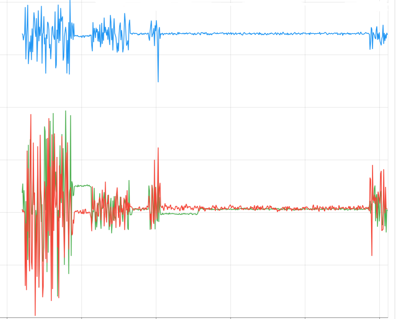
10.3 VIBMOD4: Detect vibration intensity
Set AT+VIBMOD=4,30000,1 to collect a set of XYZ vibration data every ten seconds.
By analyzing the data collected in the graph, we can observe that the vibration amplitude of the machine varies significantly under different working conditions. This monitoring method not only helps to determine in real time whether the machine is operating normally but also allows for the early detection of any abnormal changes in vibration frequency. This, in turn, helps to effectively prevent potential failures and ensures the safe and stable operation of the equipment.
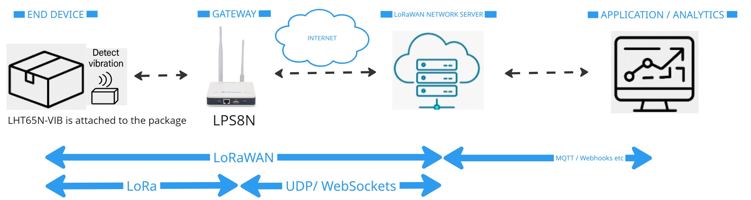
10.4 Package Handling Monitoring
Attach the LHT65N-VIB sensor to sensitive shipments (e.g., medical equipment, electronics, artwork) to detect excessive vibrations or improper handling during transport. The temperature and humidity readings can confirm whether the shipment stayed within safe environmental ranges.
Benefit:
- Identify mishandling during transport.
- Ensure product quality upon arrival.
- Provide proof for insurance or logistics partners
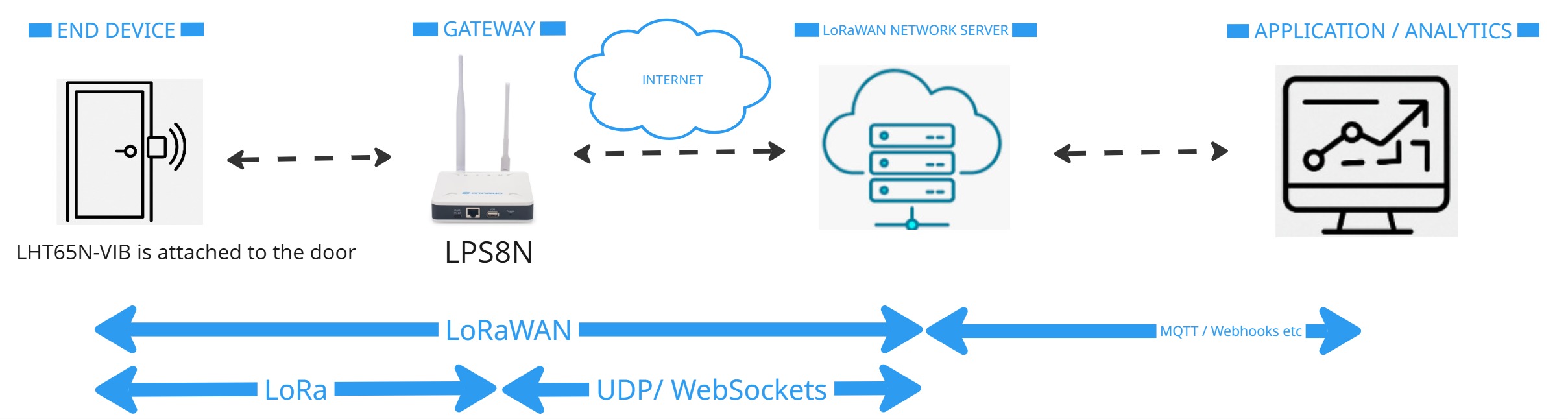
10.5 Door and Gate Activity Monitoring
Install the sensor on warehouse doors, server room doors, or remote facility gates to detect unexpected openings (vibration when the door moves) and monitor ambient conditions inside critical areas.
Benefit:
- Detect unauthorised access attempts.
- Log normal usage patterns.
- Monitor temperature-sensitive rooms like server rooms or medicine storage.
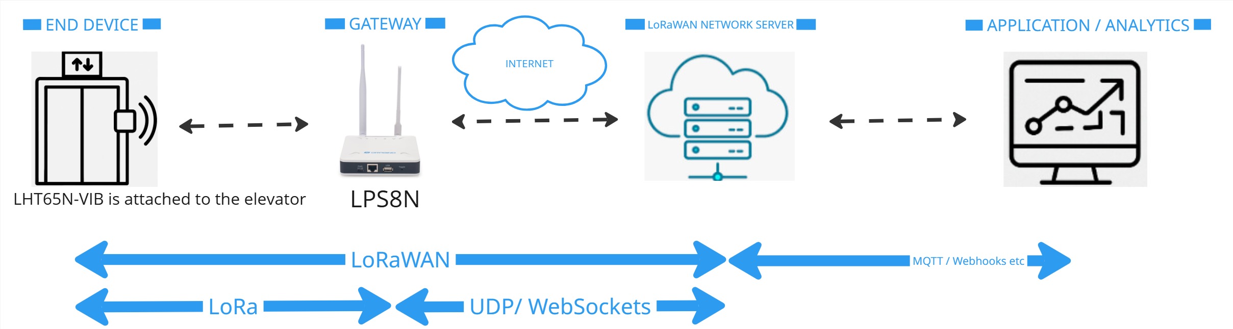
10.6 Elevator and Escalator Monitoring
Place a sensor on elevator motors or escalator machinery to detect irregular vibration patterns. Combine vibration events with temperature trends to predict mechanical issues early.
Benefit:
- Early warning of potential breakdowns.
- Reduce maintenance costs.
- Improve building safety.
10.7 Remote Farm Equipment Status Check
Install the sensor on stationary farm equipment (like irrigation pumps or grain dryers) located across large fields. Monitor when equipment vibrates (operating) and stop (idle) without needing a technician physically present.
Benefit:
- Remote confirmation of equipment operation.
- Temperature and humidity data help optimize agricultural processes.
- Save time and reduce manual checks.
0