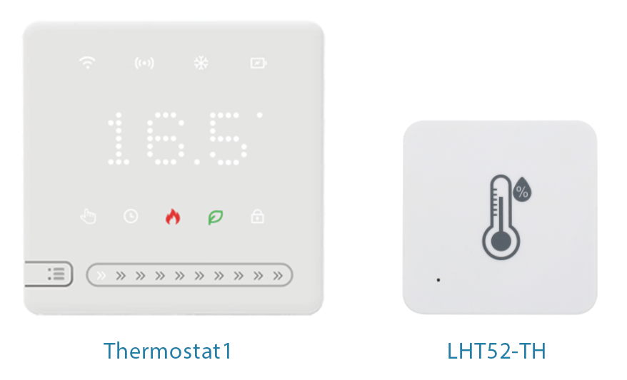
Thermostat1
1. Introduction
1.1 What is LoRaWAN Thermostat1
The Dragino Thermostat1 is a LoRaWAN-based smart thermostat designed specifically for the North American HVAC market. It is compatible with a wide range of 24VAC HVAC systems, including:
- Conventional Heating & Cooling: Supports 2H/2C and 1H/1C configurations
- Heat Pump Systems: Supports 3H/2C and 4H/2C configurations
- Boiler or Radiant Heating Systems with air handler and conventional cooling/heating
Leveraging LoRaWAN long-range wireless communication, the Thermostat1 enables remote temperature monitoring and control, significantly reducing the cost and complexity of installation and maintenance—especially in large or distributed facilities.
1.2 Features
- LoRaWAN US915 Class C protocol
- Local and remote temperature control for flexible operation
- Easy integration into building automation and energy management systems
- Wireless deployment minimizes wiring requirements and installation costs
- Scalable for large commercial facilities with centralized control needs
1.3 Specification
Power supply mode: 18-30VAC 60Hz Temperature setting accuracy: 0.5 °F Temperature setting range: 41 °F ~ 95°F Temperature display accuracy: 0.5 °F Transportation temperature range: 14 °F ~ 140 °F Working environment temperature: 32 °F ~ 122 °F
1.4 Applications
- Offices, industrial buildings, campuses
- Hotels and resorts
- Retail chains with multiple locations
- Schools & universities
- Healthcare facilities
Thermostat1 delivers a cost-effective, scalable, and reliable solution for modern commercial HVAC management.
1.5 Panel and Function
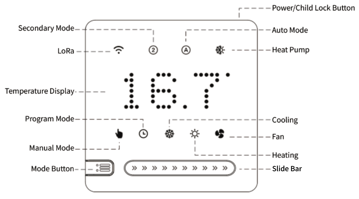
1.5.1 Operation Instructions
| Button | Function |
|---|---|
| Short press the power button to turn on/off the device; long press to turn on/off the child lock. | |
| With the power on, briefly press the Mode button to switch between Manual and Automatic modes. With the power off, press and hold for 3 seconds to enter the Advanced menu settings. Short presses allow you to switch between advanced options. With the power on, press and hold for 3 seconds to switch between Cooling and Heating modes (if the current output mode is Automatic and the system is multi-stage). | |
| Slide Bar | When the device is powered on, slide the bar left or right to adjust the temperature. The minimum unit is 0.5°F. Slide left or right to adjust the parameter (see Advanced Options Settings below). |
1.5.2 Programming mode setting
Device is powered on, programming can be done on the client side.
| Mode | Time period | Default time | Default temp |
| Cooling | working day | 06:00 | 77℉ |
| 08:00 | 66℉ | ||
| 11:30 | 77℉ | ||
| 12:30 | 66℉ | ||
| 17:00 | 77℉ | ||
| 22:00 | 66℉ | ||
| Rest Day | 08:00 | 77℉ | |
| 23:00 | 66℉ | ||
| Heating | working day | 06:00 | 72℉ |
| 08:00 | 61℉ | ||
| 11:30 | 72℉ | ||
| 12:30 | 61℉ | ||
| 17:00 | 72℉ | ||
| 22:00 | 61℉ | ||
| Rest Day | 08:00 | 72℉ | |
| 23:00 | 61℉ |
1.5.3 Advanced Options Settings
In the off state, press and hold the mode button for 3 seconds to enter the advanced option settings, press the mode button to switch the advanced option parameters, slide the slider left and right to set the parameters, and press the power button to save and exit .
| Parameter item | Parameter Name (Factory Default) | Select by sliding left and right on the slider | Unit | Functional meaning |
|---|---|---|---|---|
| 1 | System (0) | 0 ~ 4 | / | 0: Single cooling; 1: Single heating; One cooling and one heating; 3: One cooling and two heating; 4: Two cooling and two heating |
| 2 | Output Mode (0) | 0 ~ 3 | / | 0: Cooling; 1: Heating; 2: Automatic; 3: AUX mode |
| 3 | Startup Mode (0) | 0 ~ 1 | / | 0: Slow speed -- When the temperature difference is>=3 ℉, start heating/cooling; 1: Quick -- When the temperature difference is>=1 ℉, start heating/cooling |
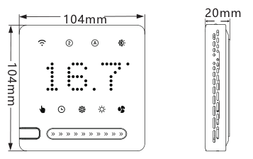
1.6 Dimension
1.7 Pin Mapping
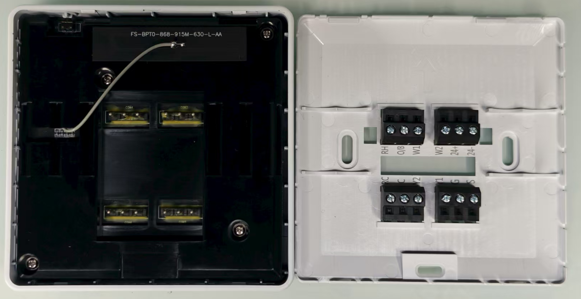
| Terminal | Function |
| 24+ / 24 - | 24-volt AC power supply from the HVAC system’s transformer. 24+ is the hot side, 24- is the common/neutral side. |
| RC | (Red Cooling). Power (24VAC) for cooling systems. |
| C | (Common). The return path for the 24VAC power (often called “common wire” or “C-wire”). |
| Y1 | First-stage cooling output. |
| Y2 | Second-stage cooling output. |
| G | Controls the fan relay (blower fan) |
| S | (Sensor) , External temperature or sensor input (varies by manufacturer). |
| RH | (Red Heating): Power (24VAC) for heating systems. |
| O/B | Heat pump reversing valve control. |
| W1 | First-stage heating output. |
| W2 | Second-stage heating output. |
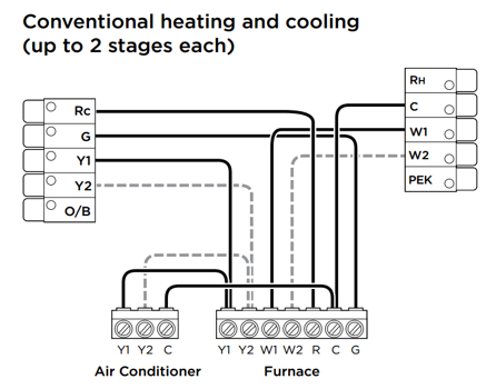
1.8 Wiring
1.8.1 Traditional single-stage and multi-level systems
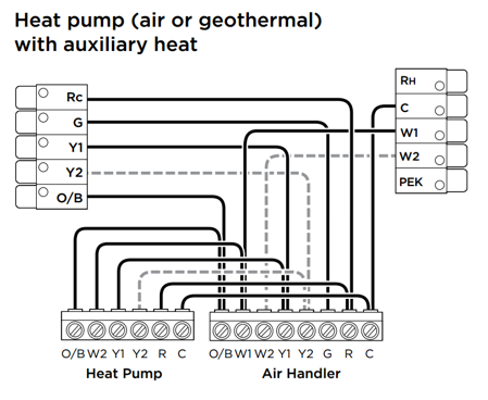
1.8.2 Heat pump+auxiliary heating system
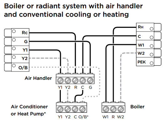
1.8.3 Boiler+air conditioning system
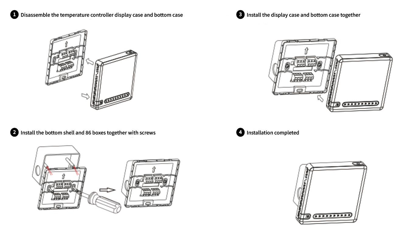
1.9 Installation
2. Configure Thermostat1 to connect to LoRaWAN network
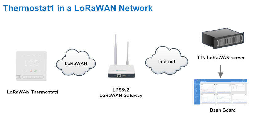
2.1 How it works
The Thermostat1 is configured as LoRaWAN OTAA Class C mode by default. It has OTAA keys to join LoRaWAN network. To connect a local LoRaWAN network, you need to input the OTAA keys in the LoRaWAN IoT server and press the button to activate the Thermostat1. It will automatically join the network via OTAA and start to send the sensor value. The default uplink interval is 1 hour.
2.2 Quick guide to connect to LoRaWAN server (OTAA)
Following is an example for how to join the TTN v3 LoRaWAN Network. Below is the network structure; we use the LPS8v2 as a LoRaWAN gateway in this example.
The LPS8v2 is already set to connected to TTN network , so what we need to now is configure the TTN server.
Step 1: Create a device in TTN with the OTAA keys from Thermostat1.
Each Thermostat1 is shipped with a sticker with the default device EUI as below:
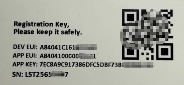
You can enter this key in the LoRaWAN Server portal. Below is TTN screen shot:
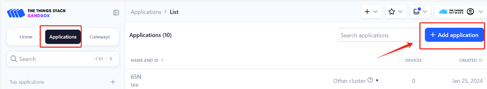
Create the application.
- On the home screen, click the + Add application button.
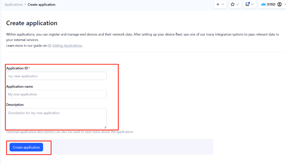
- On the Create application page, enter an Application ID to identify your **application **within The Things Stack and provide an Application name. Read https://thethingsindustries.com/docs/integrations/adding-applications for more information on how to do that.
- Click the Create application button.
Add devices to the created Application
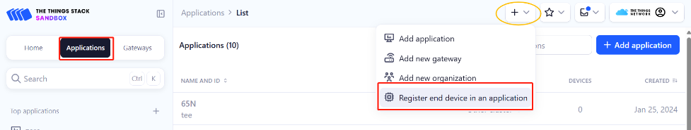
- After creating the application, you will be redirected to the Application overview page.
- On the Application overview page, click the + Register end device button.
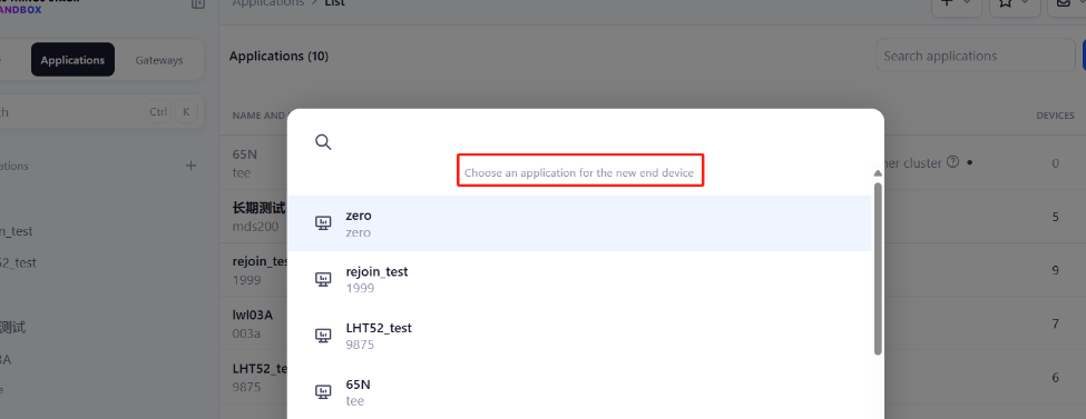
Enter end device specifics manually
We use Over The Air Activation (**OTAA) **to activate Thermostat1 with The Things Stack. OTAA is the most secure way of activating an end device with a LoRaWAN network server.
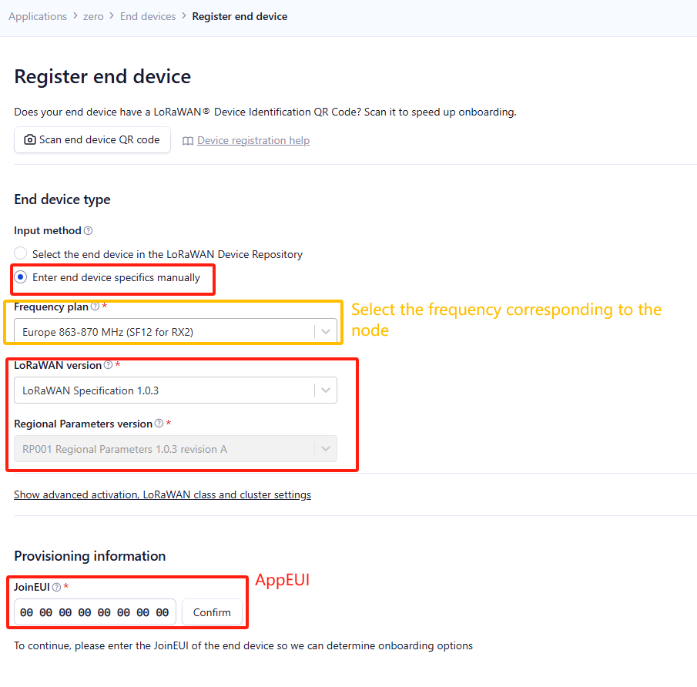
- On the Register end device page, select the ‘Enter end device specifics manually’ option under the input method.
- Select the correct Frequency plan and LoRaWAN version. The Regional parameters version will appear automatically based on the LoRaWAN version
Thermostat1 uses the ClassC protocol. Please use the ClassC configuration when registering
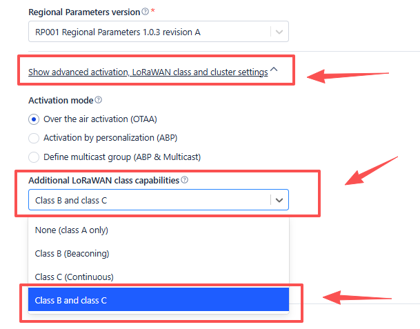
The Frequency plan should match the frequency of the Thermostat1.
Using the registration information sheet that comes with the Thermostat1,
- Fill the JoinEUI. The Thermostat1 uses **AppEUI **instead of JoinEUI. You can enter it in the JoinEUI text box. Then click the **Confirm **button.
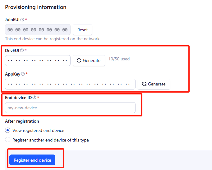
Add DevEUI and AppKey
- Enter the **DevEUI **and AppKey.
- Enter an End device ID that can be used to identify your Thermostat1 within this application.
Click the Register end device button.
**Step 2: **Add decoder
LoRaWAN uplink and downlink payloads are encoded. To understand the data, you need a small script to decode them. We use a JavaScript function for this. It is called a payload formatter. It reads the payload and extracts useful information, such as relay status, event type, and timestamp. We have written a JavaScript function to decode uplinks from the Thermostat1 device.
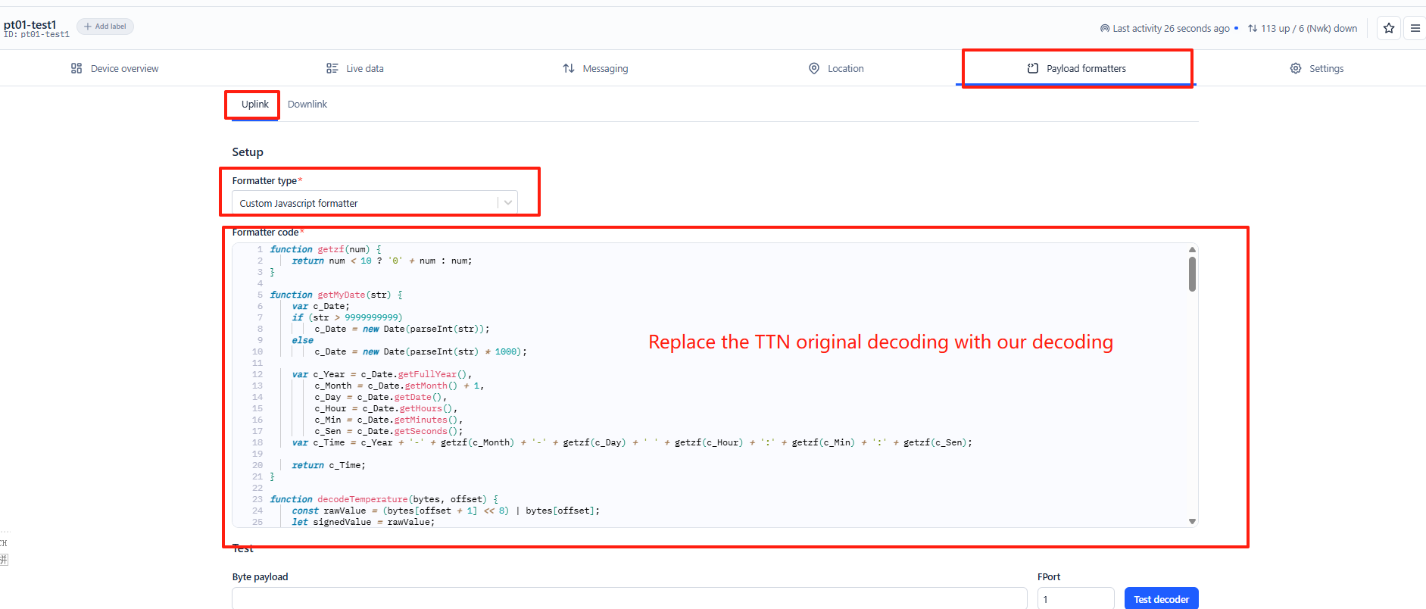
To add an uplink payload formatter code to The Things Stack, follow the steps below:
- Go to your Thermostat1 device page and click Payload formatters.
- Click, Uplink.
- Select Custom Javascript formatter from the **Formatter type **drop-down list.
- Now copy the Uplink Formatter code from here: https://github.com/dragino/dragino-end-node-decoder/tree/main/
- Then paste it in the **Formatter code **box:
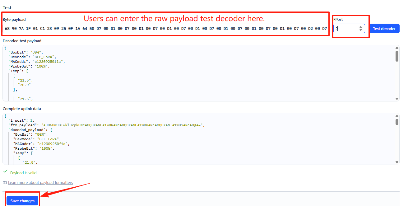
You can now test the formatter code with a sample payload.
- Enter 68 90 7A 1F 01 C1 23 09 25 0F 1A 64 50 D7 00 D1 00 D7 D1 00 D7 00 D1 00 in the Byte payload box.
- Change the **FPort **to 2 (because our payload formatter only accepts uplinks from FPort 2).
- Click the Test decoder button.
The payload will be decoded into the following JSON object and shown in the Decoded test payload box.
To save the payload formatter, click the Save changes button.
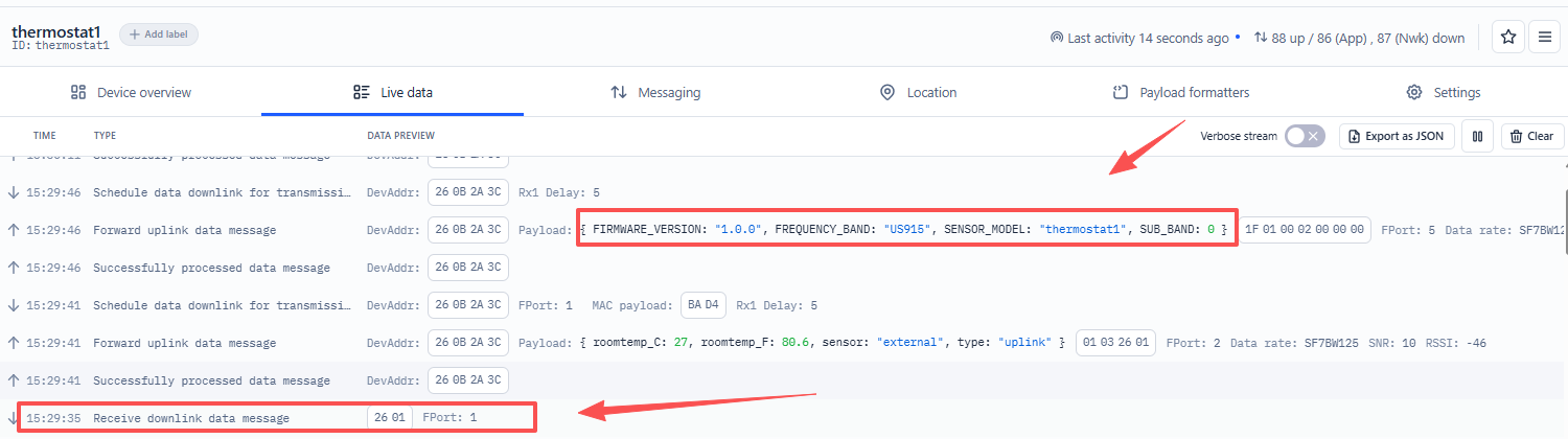
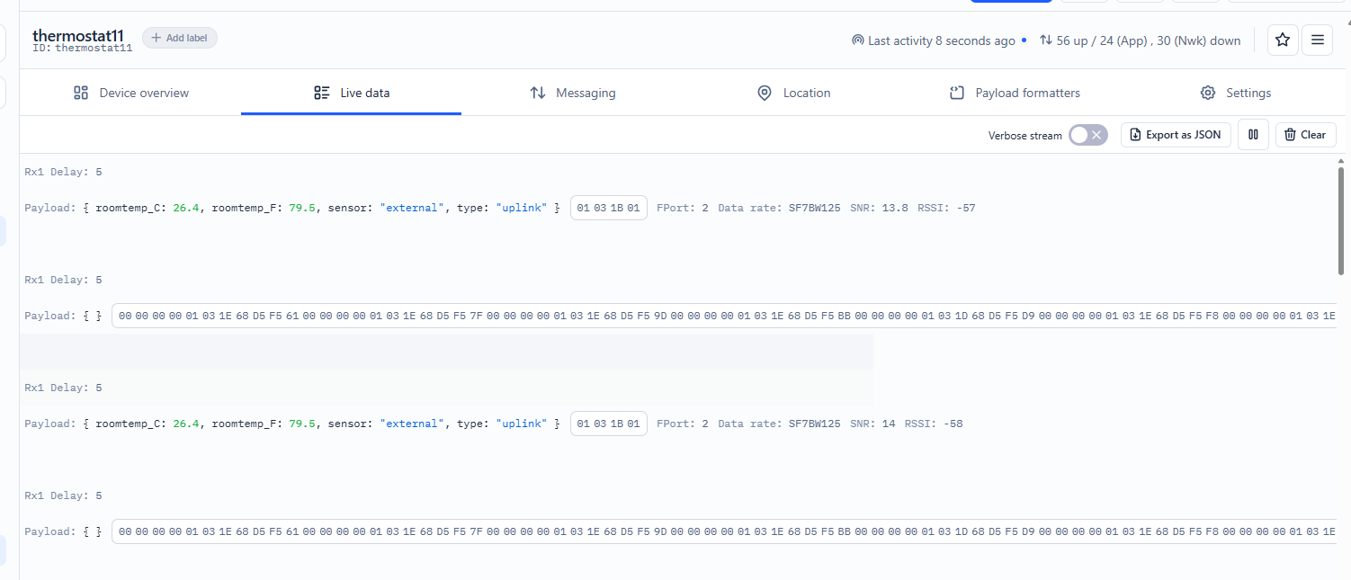
After applying the uplink payload formatter, you can see that all uplink payloads shown in the Live Data section are decoded into fields.
Step 3: Activate the Thermostat1
Press the **ACT **button for 3 seconds to activate the Thermostat1. After a successful join, it will start uploading messages to The Things Stack, and you can see them in the Live data panel.
2.3 Uplink Payload
2.3.1 Device Status, FPORT=5
Users can use the downlink command(0x26 01) to ask Thermostat1 to send device configure detail, include device configure status. Thermostat1 will uplink a payload via FPort=5 to server.
The Payload format is as below.
| Device Status (FPORT=5) | |||||
| Size (bytes) | 1 | 2 | 1 | 1 | 2 |
| Value | Sensor Model | Firmware Version | Frequency Band | Sub-band | Undefined |
Example parse in TTNv3
Sensor Model: For Thermostat1, this value is 0x1F
Firmware Version: 0x0110, Means: v1.1.0 version
Frequency Band:
0x01: EU868
0x02: US915
0x03: IN865
0x04: AU915
0x05: KZ865
0x06: RU864
0x07: AS923
0x08: AS923-1
0x09: AS923-2
0x0a: AS923-3
0x0b: CN470
0x0c: EU433
0x0d: KR920
0x0e: MA869
Sub-Band:
AU915 and US915:value 0x00 ~ 0x08
CN470: value 0x0B ~ 0x0C
Other Bands: Always 0x00
2.3.2 Roomtemp Sensor uplink Data. FPORT=2
When using an external sensor for matching, it will send this uplink.
Please refer to this command for how to match
Sensor Data is uplink via FPORT=2
| Size(bytes) | 1 | 2 | 1 |
|---|---|---|---|
| Value | Uplink_type | Roomtemp | Sensor_type |
Example parse in TTNv3
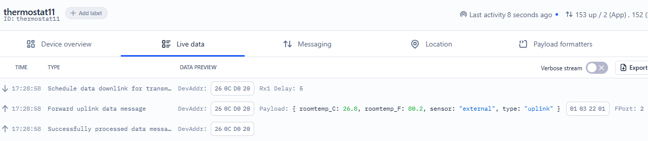
Uplink type Example:
If payload is: 01H: uplink
If payload is: 02H: downlink_set
If payload is: 03H: Internal function uplink Data
Roomtemp The purpose is to analyze the indoor temperature Example:
If payload is: 0105H: (0105 & 8000 == 0), temp = 0105H /10 = 26.1 degree
If payload is: FF3FH : (FF3F & 8000 == 1) , temp = (FF3FH - 65536)/10 = -19.3 degrees.
(FF3F & 8000: Judge whether the highest bit is 1, when the highest bit is 1, it is negative)
Sensor type Example:
If payload is: 01H: internal
If payload is: 00H: external
2.3.3 Downlinkget Data. FPORT=2
When you issue a query command, it will return the corresponding controller data
Please refer to the following link for query commands
Sensor Data is uplink via FPORT=2
| Size(bytes) | 1 | 1 | 1 | 4 |
|---|---|---|---|---|
| Value | Uplink_type | Mode | Sensor_type | Feature_value |
Example parse in TTNv3
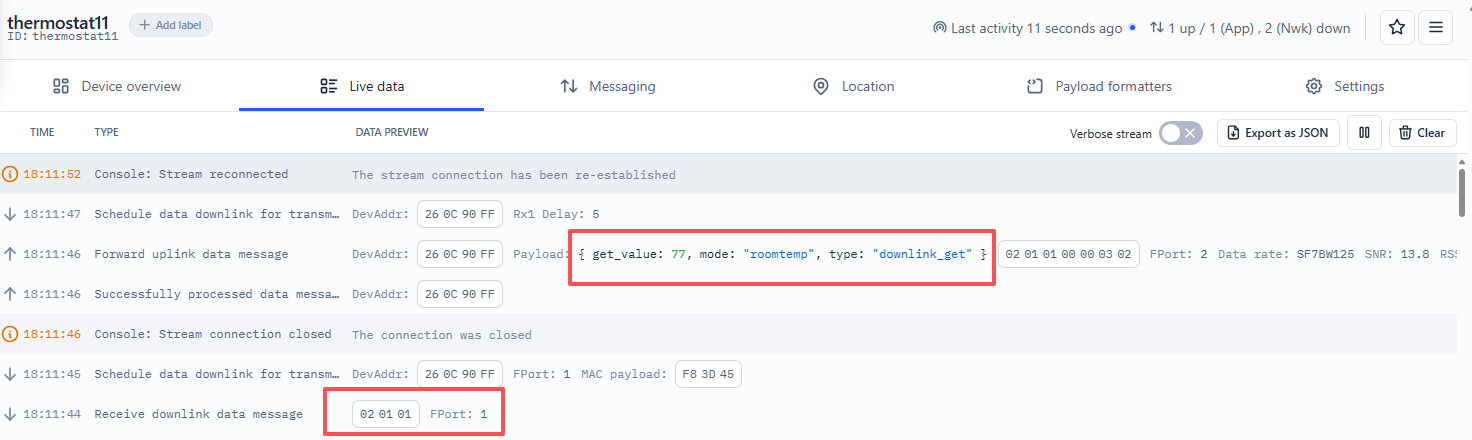
Uplink type Example:
If payload is: 01H: uplink
If payload is: 02H: downlink_set
If payload is: 03H: Internal function uplink Data
Mode: Example:
If payload is: 01H: Room Temperature
If payload is: 02H: Set Cooling Temperature
Please refer to the table below:
| Hex | Function | Type | Range / Options | Unit | Operation | Default Value |
|---|---|---|---|---|---|---|
| 01 | Room Temperature | int | 33 - 122 | °F | Read Only | - |
| 02 | Set Cooling Temperature | int | 43 - 95 | °F | Read/Write | - |
| 03 | Set Heating Temperature | int | 43 - 95 | °F | Read/Write | - |
| 04 | Output Mode | string | cool/heat/fan/dry | - | Read/Write | - |
| 05 | Start Mode | string | cool/heat/fan/dry | - | Read/Write | - |
| 06 | Fan Mode | string | low/medium/high/auto | - | Read/Write | auto |
| 07 | Temperature Calibration | int | -5 ~ +5 | °F | Read/Write | 0 |
| 08 | Secondary Startup Condition | int | 1 - 10 | - | Read/Write | - |
| 09 | Compressor Delay | int | 2 - 10 | min | Read/Write | 3 |
| 0A | System Mode | string | 0: Cool Only 1: Heat Only 2: 1C1H 3: 1C2H 4: 2C2H | - | Read/Write | 0 (Cool Only) |
| 0B | Child Lock | string | lock/unlock | - | Read/Write | unlock |
| 0C | Power On/Off | string | on/off | - | Read/Write | off |
| 0D | Control Mode | string | manual/auto | - | Read/Write | manual |
| 0E | Weekday Period 1 Temperature | int | 43 - 95 | °F | Read/Write | 85 |
| 0F | Weekday Period 2 Temperature | int | 43 - 95 | °F | Read/Write | 78 |
| 10 | Weekday Period 3 Temperature | int | 43 - 95 | °F | Read/Write | 85 |
| 11 | Weekday Period 4 Temperature | int | 43 - 95 | °F | Read/Write | 78 |
| 12 | Weekend Period 1 Temperature | int | 43 - 95 | °F | Read/Write | 85 |
| 13 | Weekend Period 2 Temperature | int | 43 - 95 | °F | Read/Write | 78 |
| 14 | Weekend Period 3 Temperature | int | 43 - 95 | °F | Read/Write | 85 |
| 15 | Weekend Period 4 Temperature | int | 43 - 95 | °F | Read/Write | 78 |
| 16 | Holiday Period 1 Temperature | int | 43 - 95 | °F | Read/Write | 85 |
| 17 | Holiday Period 2 Temperature | int | 43 - 95 | °F | Read/Write | 78 |
| 18 | Holiday Period 3 Temperature | int | 43 - 95 | °F | Read/Write | 85 |
| 19 | Holiday Period 4 Temperature | int | 43 - 95 | °F | Read/Write | 78 |
| 1A | Weekday Period 1 Time | int | 0 - 1439 | min | Read/Write | 480 (08:00) |
| 1B | Weekday Period 2 Time | int | 0 - 1439 | min | Read/Write | 720 (12:00) |
| 1C | Weekday Period 3 Time | int | 0 - 1439 | min | Read/Write | 1020 (17:00) |
| 1D | Weekday Period 4 Time | int | 0 - 1439 | min | Read/Write | 1320 (22:00) |
| 1E | Weekend Period 1 Time | int | 0 - 1439 | min | Read/Write | 480 (08:00) |
| 1F | Weekend Period 2 Time | int | 0 - 1439 | min | Read/Write | 720 (12:00) |
| 20 | Weekend Period 3 Time | int | 0 - 1439 | min | Read/Write | 1020 (17:00) |
| 21 | Weekend Period 4 Time | int | 0 - 1439 | min | Read/Write | 1320 (22:00) |
| 22 | Holiday Period 1 Time | int | 0 - 1439 | min | Read/Write | 480 (08:00) |
| 23 | Holiday Period 2 Time | int | 0 - 1439 | min | Read/Write | 720 (12:00) |
| 24 | Holiday Period 3 Time | int | 0 - 1439 | min | Read/Write | 1020 (17:00) |
| 25 | Holiday Period 4 Time | int | 0 - 1439 | min | Read/Write | 1320 (22:00) |
Sensor type Example:
If payload is: 01H: internal
If payload is: 00H: external
Feature_value: Example:
Please refer to the corresponding value of Mode in the table
2.3.4 Internal function uplink Data. FPORT=2
Fixed uplink information of internal devices
The Payload format is as below.
| Size(bytes) | 1 | ... |
|---|---|---|
| Value | Uplink_type | (Feature_list+Feature_value)+...............+(Feature_list+Feature_value) |
Example parse in TTNv3
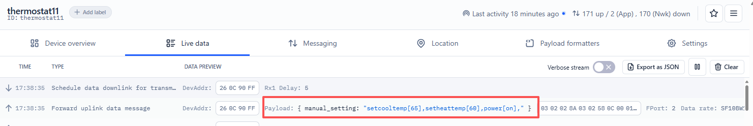
Uplink type Example:
If payload is: 01H: uplink
If payload is: 02H: downlink_set
If payload is: 03H: Internal function uplink Data
Feature_List+Feature_value Please refer to the table below:
| Function | hex | Range |
|---|---|---|
| Room Temperature | 01 | 33-122 |
| Set Cooling Temperature | 02 | 43-95 |
| Set Heating Temperature | 03 | 43-95 |
| Output Mode | 04 | Cooling/Heating/Fan/Dehumidification |
| Start Mode | 05 | Cooling/Heating/Fan/Dehumidification |
| Fan Mode | 06 | Low/Medium/High/Auto |
| Temperature Calibration | 07 | -5 ~ +5 |
| Secondary Startup Condition | 08 | 1-10 |
| Compressor Delay | 09 | 1-10 |
| System Mode | 0A | Cooling/Heating/Fan/Dehumidification |
| Child Lock | 0B | Lock/Unlock |
| Power On/Off | 0C | On/Off |
| Control Mode | 0D | Manual/Program |
| Weekday Period 1 Temperature | 0E | 43-95 |
| Weekday Period 2 Temperature | 0F | 43-95 |
| Weekday Period 3 Temperature | 10 | 43-95 |
| Weekday Period 4 Temperature | 11 | 43-95 |
| Weekend Period 1 Temperature | 12 | 43-95 |
| Weekend Period 2 Temperature | 13 | 43-95 |
| Weekend Period 3 Temperature | 14 | 43-95 |
| Weekend Period 4 Temperature | 15 | 43-95 |
| Holiday Period 1 Temperature | 16 | 43-95 |
| Holiday Period 2 Temperature | 17 | 43-95 |
| Holiday Period 3 Temperature | 18 | 43-95 |
| Holiday Period 4 Temperature | 19 | 43-95 |
| Weekday Period 1 Time | 1A | 0-1439 |
| Weekday Period 2 Time | 1B | 0-1439 |
| Weekday Period 3 Time | 1C | 0-1439 |
| Weekday Period 4 Time | 1D | 0-1439 |
| Weekend Period 1 Time | 1E | 0-1439 |
| Weekend Period 2 Time | 1F | 0-1439 |
| Weekend Period 3 Time | 20 | 0-1439 |
| Weekend Period 4 Time | 21 | 0-1439 |
| Holiday Period 1 Time | 22 | 0-1439 |
| Holiday Period 2 Time | 23 | 0-1439 |
| Holiday Period 3 Time | 24 | 0-1439 |
| Holiday Period 4 Time | 25 | 0-1439 |
2.4 Payload Decoder file
In TTN, use can add a custom payload so it shows friendly reading
In the page Applications --> Payload Formats --> Custom --> decoder to add the decoder from:https://github.com/dragino/dragino-end-node-decoder/tree/main/Thermostat1
2.5 Datalog Feature
Datalog Feature is to ensure IoT Server can get all sampling data from Sensor even if the LoRaWAN network is down. For each sampling, Thermostat1 will store the reading for future retrieving purposes.
2.5.1 Ways to get datalog via LoRaWAN
With the platform downlink 07 01, turn on the device to send None-ACK message function automatically, Thermostat1 will wait for every upstream ACK, when there is no LoRaWAN network, Thermostat1 will mark these records as non ack message and store the sensor data, and wait for the network to be restored (10s interval) to send all the messages.
a) Thermostat1 will do an ACK check for data records sending to make sure every data arrive server.
b) When automatic sending of None-ACK messages is enabled, the Thermostat1 will send data in CONFIRMED mode, but if an ACK is not received, the Thermostat1 will not resend the packet, it will only mark it as a NONE-ACK message. On subsequent uplinks, if the Thermostat1 receives an ACK, the Thermostat1 will consider the network connected and resend all NONE-ACK messages.
2.5.2 Unix TimeStamp
Thermostat1 uses Unix TimeStamp format based on
User can get this time from link: https://www.epochconverter.com/ :
Below is the converter example
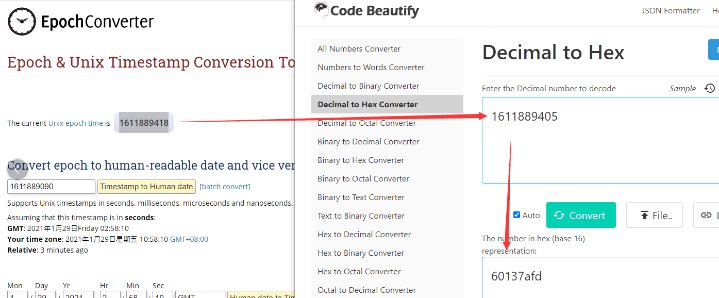
So, we can use downlink 3060137afd00 to set the current time 2021 – Jan -- 29 Friday 03:03:25
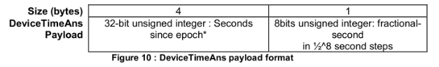
2.5.3 Set Device Time
Users need to run downlink command 28 01 to enable the synchronization time.
Once Thermostat1 Joined LoRaWAN network, it will send the MAC command (DeviceTimeReq) and the server will reply with (DeviceTimeAns) to send the current time to Thermostat1 . If Thermostat1 fails to get the time from the server, Thermostat1 will use the internal time and wait for next time request (The default time is once every 10 days.).
Note: LoRaWAN Server need to support LoRaWAN v1.0.3(MAC v1.0.3) or higher to support this MAC command feature, Chirpstack,TTN V3 v3 and loriot support but TTN V3 v2 doesn't support. If server doesn't support this command, it will through away uplink packet with this command, so user will lose the packet with time request for TTN V3 v2 if when the automatic time synchronization function is turned on. Downlink Command: 0x28
- Example: 0x28 01 // Automatic time synchronization Enabled
- Exampie: 0x28 00 // Automatic time synchronization Disable.
2.5.4 Datalog Uplink payload (FPORT=3)
The Datalog uplinks will use below payload format.
Retrieval data payload:
| Size(bytes) | ....... | 4 |
|---|---|---|
| Value | datalog data | Unix Time Stamp |
No ACK Message: 1: This message means this payload is fromn Uplink Message which doesn't get ACK from the server before ( for Automatically send None-ACK feature)
DatalogReply: 1: This message is a poll message reply.
-
Poll Message Flag is set to 1.
-
Each data entry is 8 bytes, to save airtime and battery, devices will send max bytes according to the current DR and Frequency bands.
For example, in US915 band, the max payload for different DR is:
a) DR0: max is 11 bytes so one entry of data
b) DR1: max is 53 bytes so devices will upload 4 entries of data (total 44 bytes)
c) DR2: total payload includes 11 entries of data
**d) DR3: **total payload includes 22 entries of data.
If devise doesn't have any data in the polling time. Device will uplink 8 bytes of 0
Example:
If user sends below downlink command: 31681D4580681D6FB005
Where : Start time: 681D4580 = time 25/5/9 08:00:00
Stop time: 681D6FB0 = time 25/5/9 11:00:00
Thermostat1 will uplink this payload.
68 1D 5C 51 04 00 00 40 68 1D 6A 61 03 00 00 40
Where the first 8 bytes is for the first entry:
68 1D 5C 51 04 00 00 40
**Datalog data **is 00 00 00 00 01 03 1E = 01 (external probe) 03 1E(room temp) /10=798/10=79.8℉
Unix time is 0x68 1D 5C 51=1746754641s=25/5/9 09:37:00
的的
2.6 Frequency Plans
The Thermostat1 uses OTAA mode and below frequency plans by default. Each frequency band use different firmware, user update the firmware to the corresponding band for their country.
http:///docs/wiki/Configuration/end-node/frequency-band/
2.7 Use Remote Temperature Sensor
3. Configure Thermostat1
3.1 Configure Methods
Thermostat1 supports below configure method:
- LoRaWAN Downlink. Instruction for different platforms: See IoT LoRaWAN Server section.
3.2 General Commands
These commands are to configure:
- General system settings like: uplink interval.
- LoRaWAN protocol & radio related command.
They are same for all Dragino Devices which support DLWS-005 LoRaWAN Stack. These commands can be found on the wiki:
http:///docs/wiki/Configuration/end-node/at-commands-downlink/
3.3 Commands special design for Thermostat1
These commands only valid for Thermostat1 , as below:
3.3.1 Set Transmit Interval Time
AT Command:
There is no AT command to set TDC time.
Feature: Change LoRaWAN End Node Transmit Interval.
Downlink Command: 0x01
Format: Command Code (0x01) followed by 3 bytes time value.
If the downlink payload=0100003C, it means set the END Node's Transmit Interval to 0x00003C=60(S), while type code is 01.
- Example 1: Downlink Payload: 0100001E // Set Transmit Interval (TDC) = 30 seconds
- Example 2: Downlink Payload: 0100003C // Set Transmit Interval (TDC) = 60 seconds
3.3.2 Make Thermostat1 send an uplink
Send a LoRaWAN downlink to ask device send an uplink.
Downlink Payload: 0x08 FF
Sensor will upload Device Status via FPORT=2. See payload section for detail.
3.3.3 Set the internal probe or the external probe
AT Command:
No AT command to control internal probe or external probe
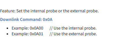
Feature: Set the internal probe or the external probe.
Downlink Command: 0x0A
- Example: 0x0A00 // Use the internal probe.
- Example: 0x0A01 // Use the external probe.
3.3.4 Set the matching code
Note:Thermostat1 needs to be set to external mode AT Command:
There is no AT Command to set the matching code
Feature: Set the matching code(The default matching code is AABB)
Downlink Command: 0x0B
- Example: 0x0B AA CC // Set the matching code to AACC
LHT52 needs to configure this command to complete pairing: Note:This command is used on LHT52-HT
AT+TXCONFIG=a,b,c,d,e,f,g
a: Have you enabled the LoRa packet sending mode?
B: Sending frequency. 923300,000
C: Transmission bandwidth. 0:125 KHZ; 1:250kHz; 2:500kHz.
D: Sent SF.
E: DVEUI matched with Thermostat1
F: The port for sending.
G: Matching code.
AT Command:
AT+TXCONFIG=1,923300000,2,12,xxxxxxxxxx,2,ABCD
Downlink Payload (prefix 0x08): Downlink command(2bytes ) 08 aa ==> Modify the value of a
- Example1: 0x08 01 // enabled the LoRa packet sending mode
- Example2: 0x08 00 // exit the LoRa packet sending mode
**Downlink command(10 bytes )**Note:Generally, the device only needs to modify parameter E
08 aa ee ee ee ee ee ee ee ==> Modify the value of E * Example1: 0x08 01 A8 40 41 9E E3 5A DD 62 // enabled the LoRa packet sending mode and set the Thermostat1deveui that needs to be matched * Example2: 0x08 00 // exit the LoRa packet sending mode Downlink command(19 bytes ) 08 aa bb bb bb bb cc dd ee ee ee ee ee ee ee ee ff gg gg ==> Modify the entire command
aa // Have you enabled the LoRa packet sending mode?(1 bytes)
01:enabled the LoRa packet sending mode
00:exit the LoRa packet sending mode
bb bb bb bb // The frequency value needs to be converted into hexadecimal(4 bytes)
923300000(DEC) ==>370870A0(HEX)
923100000(DEC) ==>37056360(HEX)
cc // Transmission bandwidth(1 bytes)
00:125kHZ
01:250kHz
02:500kHz
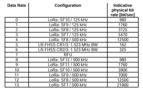
dd // Set SF(Please set the SF you need according to the table below, and pay attention to your Transmission bandwidth)(1 bytes)
ee ee ee ee ee ee ee ee // DVEUI matched with Thermostat1(8 bytes)
A8 40 41 9E E3 5A DD 62 ==>A8 40 41 9E E3 5A DD 62
ff // The port for sending(1 bytes)value needs to be converted into hexadecimal
14 ==>0e
gg gg//Matching code(2 bytes)
Default is AABB
- Example1: 0x08 01 37 05 63 60 02 0C A8 40 41 9E E3 5A DD 62 02 AB CD // Smae as
AT+TXCONFIG=1,923100000,2,12,A840419EE35ADD62,2,ABCD
3.3.5 Query or set the Thermostat1 register command
Feature: Query or set the Thermostat1 register command
Note: All configurable temperature options are in Fahrenheit AT Command:
There is no AT Command to query or set the Thermostat1 register command
The downlink command is 3 bytes or 5 bytes (hexadecimal). Downlink Payload (prefix 0x02):
- Example: 0x02 01 01 // Read room temperature
- Example: 0x02 02 02 00 64 // Set Cooling Temperature to 10℉
First byte :
Type code (0x02)
Second byte (aa):
The values range from 01 to 45(HEX), and each number has a corresponding function instruction, as shown in the following figure:
| Hex | Function | Type | Range / Options | Unit | Operation | Default Value |
|---|---|---|---|---|---|---|
| 01 | Room Temperature | int | 33 - 122 | °F | Read Only | - |
| 02 | Set Cooling Temperature | int | 43 - 95 | °F | Read/Write | - |
| 03 | Set Heating Temperature | int | 43 - 95 | °F | Read/Write | - |
| 04 | Output Mode | string | cool/heat/fan/dry | - | Read/Write | - |
| 05 | Start Mode | string | cool/heat/fan/dry | - | Read/Write | - |
| 06 | Fan Mode | string | low/medium/high/auto | - | Read/Write | auto |
| 07 | Temperature Calibration | int | -5 ~ +5 | °F | Read/Write | 0 |
| 08 | Secondary Startup Condition | int | 1 - 10 | - | Read/Write | - |
| 09 | Compressor Delay | int | 2 - 10 | min | Read/Write | 3 |
| 0A | System Mode | string | 0: Cool Only 1: Heat Only 2: 1C1H 3: 1C2H 4: 2C2H | - | Read/Write | 0 (Cool Only) |
| 0B | Child Lock | string | lock/unlock | - | Read/Write | unlock |
| 0C | Power On/Off | string | on/off | - | Read/Write | off |
| 0D | Control Mode | string | manual/auto | - | Read/Write | manual |
| 0E | Weekday Period 1 Temperature | int | 43 - 95 | °F | Read/Write | 85 |
| 0F | Weekday Period 2 Temperature | int | 43 - 95 | °F | Read/Write | 78 |
| 10 | Weekday Period 3 Temperature | int | 43 - 95 | °F | Read/Write | 85 |
| 11 | Weekday Period 4 Temperature | int | 43 - 95 | °F | Read/Write | 78 |
| 12 | Weekend Period 1 Temperature | int | 43 - 95 | °F | Read/Write | 85 |
| 13 | Weekend Period 2 Temperature | int | 43 - 95 | °F | Read/Write | 78 |
| 14 | Weekend Period 3 Temperature | int | 43 - 95 | °F | Read/Write | 85 |
| 15 | Weekend Period 4 Temperature | int | 43 - 95 | °F | Read/Write | 78 |
| 16 | Holiday Period 1 Temperature | int | 43 - 95 | °F | Read/Write | 85 |
| 17 | Holiday Period 2 Temperature | int | 43 - 95 | °F | Read/Write | 78 |
| 18 | Holiday Period 3 Temperature | int | 43 - 95 | °F | Read/Write | 85 |
| 19 | Holiday Period 4 Temperature | int | 43 - 95 | °F | Read/Write | 78 |
| 1A | Weekday Period 1 Time | int | 0 - 1439 | min | Read/Write | 480 (08:00) |
| 1B | Weekday Period 2 Time | int | 0 - 1439 | min | Read/Write | 720 (12:00) |
| 1C | Weekday Period 3 Time | int | 0 - 1439 | min | Read/Write | 1020 (17:00) |
| 1D | Weekday Period 4 Time | int | 0 - 1439 | min | Read/Write | 1320 (22:00) |
| 1E | Weekend Period 1 Time | int | 0 - 1439 | min | Read/Write | 480 (08:00) |
| 1F | Weekend Period 2 Time | int | 0 - 1439 | min | Read/Write | 720 (12:00) |
| 20 | Weekend Period 3 Time | int | 0 - 1439 | min | Read/Write | 1020 (17:00) |
| 21 | Weekend Period 4 Time | int | 0 - 1439 | min | Read/Write | 1320 (22:00) |
| 22 | Holiday Period 1 Time | int | 0 - 1439 | min | Read/Write | 480 (08:00) |
| 23 | Holiday Period 2 Time | int | 0 - 1439 | min | Read/Write | 720 (12:00) |
| 24 | Holiday Period 3 Time | int | 0 - 1439 | min | Read/Write | 1020 (17:00) |
| 25 | Holiday Period 4 Time | int | 0 - 1439 | min | Read/Write | 1320 (22:00) |
Third byte (bb):
The value of bb can be either 01 or0 2.
01 : The query command
02 : The setting command.
The fourth and fifth bytes (cc dd):
(Optional) is the value that the command needs to set. (Query commands do not require these two bytes.)
3.3.6 Confirmed Mode
AT Command:
There is no AT command to control whether Confirmed mode is enabled or disabled.
Feature: Mode for sending data for which acknowledgment was not received
Downlink Command: 0x06
- Example: 0x07 01 // Confirmed Mode enabled.
- Exampie: 0x07 00 // Confirmed Mode Disable.
3.3.7 Set the time synchronization interval
Feature: Set how often to perform time synchronization.(default is 10 days, Unit: days)
Downlink Command: 0x28
- Example: 0x28 01 // Synchronize once a day
- Exampie: 0x28 03 // Synchronize once every three days
4. OTA Firmware update
User can change firmware Thermostat1 to:
- Change Frequency band/ region.
- Update with new features.
- Fix bugs.
Firmware and changelog can be downloaded from : Firmware download link
Methods to Update Firmware:
- (Recommended way) OTA firmware update via wireless : **/docs/wiki/Configuration/gateway/ota-update-firmware-for-gateway/
5. FAQ
5.1 Why can't LHT52-TH be matched with Thermostat1?
1. Thermostat1 is not enabled as an external mode
2. No matching command was set for LHT52-TH
Please refer to this link for setup
6. Order Info
Part Number: Thermostat1-XXX
- XXX: US915: LoRaWAN US915 band
* LHT52-TH: Remote Temperature Sensor for Thermostat1
** Note: Model Thermostat1 doesn't include LHT52-TH, LHT52-TH need to be purchased seperately.**
7. Packing Info
Package Includes:
- Thermostat1: LoRaWAN Thermostat
Dimension and weight:
-
Device Size: cm
-
Device Weight: g
-
Package Size / pcs : cm
-
Weight / pcs : g
8. Support
-
Support is provided Monday to Friday, from 09:00 to 18:00 GMT+8. Due to different timezones we cannot offer live support. However, your questions will be answered as soon as possible in the before-mentioned schedule.
-
Provide as much information as possible regarding your enquiry (product models, accurately describe your problem and steps to replicate it etc) and send a mail to Support@dragino.cc.
0