LC04
1. Introduction
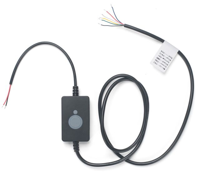
1.1 What is LC04 LoRaWAN 4 Channel low voltage control cable
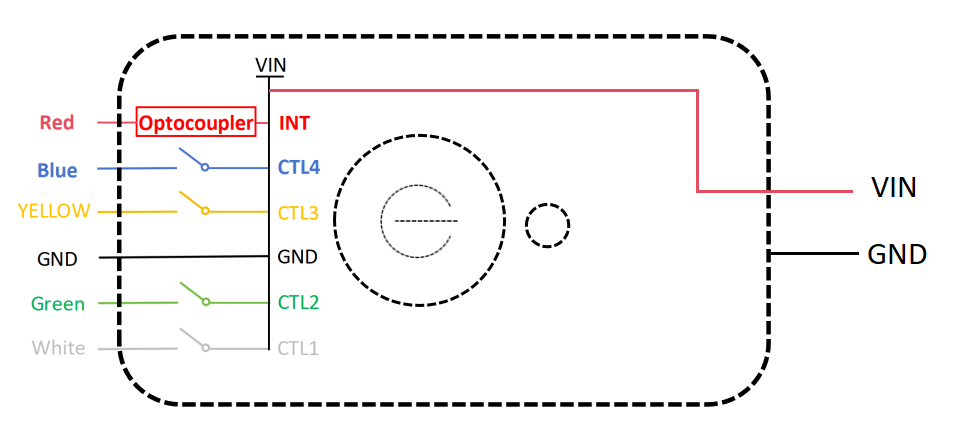
The Dragino LC04 is a LoRaWAN Class C control cable which can control up to four channel low power.
LC04 is powered by 8 ~ 28v and delivery this power to four channel outputs. User can send commands to LC04 via LoRaWAN network to configure LC04's 4-channel outputs soto control external low voltage device such as RGB Stack Light.
Each LC04 is pre-load with a set of unique keys for LoRaWAN registration, register these keys to LoRaWAN server and it will auto connect after power on.
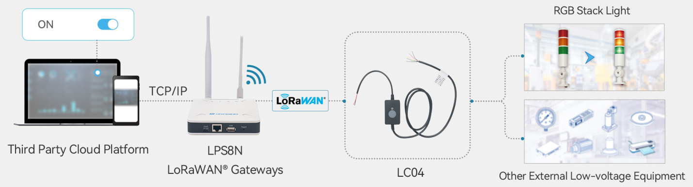
1.2 How does this product work?
1.3 Features
- LoRaWAN v1.0.3 Class C protocol
- Bands: CN470/EU433/KR920/US915/EU868/AS923/AU915/IN865
- Power and input voltage range: 8 ~ 28v
- Up to four channels low voltage output
- Output Voltage same as input voltage
- Max output current per channel : 200mA
- Support Downlink and Timing control for output
- AT Commands to change parameters
- Log function and key reset function
1.4 Specification
- Input / Output Voltage: 8 ~ 28v
- Max Current per channel: 200mA
1.5 ACT button function
| Behavior on ACT | Function | Action |
|---|---|---|
| Pressing ACT between 1s < time < 3s | Test uplink status | If LVS04-L is already Joined to the LoRaWAN network, LVS04-L will send an uplink packet, Blue led will blink once. |
| Pressing ACT for more than 3s | Restart the device | The device will reset and restart. |
| Press ACT 5 times quickly | Test the function of the channel switch | Activate the four DO channels in sequence once, with a 1-second interval between each, and then turn them all off. |
1.6 LED Indicator
The LVS04-L has a triple color LED which for easy showing different stage .While user press ACT button, the LED will work as per LED status with ACT button.
In a normal working state:
-
For each uplink, the BLUE LED will blink once.
-
For each success downlink, the PURPLE LED will blink once
-
The green LED lights up every time the button is pressed.
2. Configure LC04 to connect to LoRaWAN network
2.1 How it works
The LC04 is configured as LoRaWAN OTAA Class C mode by default. It has OTAA keys to join LoRaWAN network. To connect a local LoRaWAN network, you need to input the OTAA keys in the LoRaWAN IoT server and press the button to activate the LC04. It will automatically join the network via OTAA and start to send the sensor value. The default uplink interval is 1 hour.
2.2 Quick guide to connect to LoRaWAN server (OTAA)
Following is an example for how to join the TTN v3 LoRaWAN Network. Below is the network structure; we use the LPS8v2 as a LoRaWAN gateway in this example.
The LPS8V2 is already set to connected to TTN network , so what we need to now is configure the TTN server.
Step 1: Create a device in TTN with the OTAA keys from LC04.
Each LC04 is shipped with a sticker with the default device EUI as below:
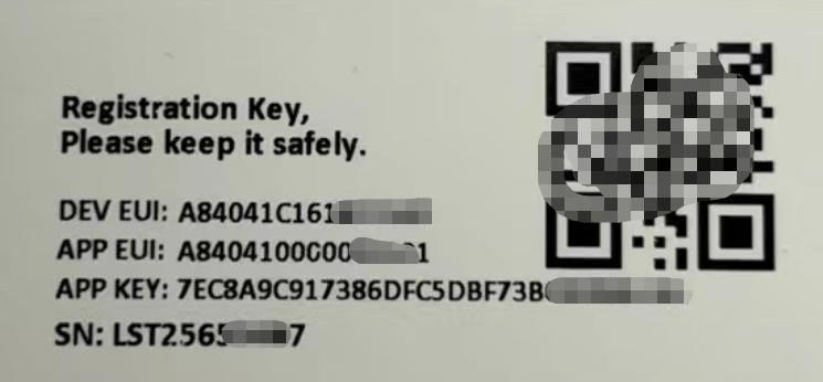
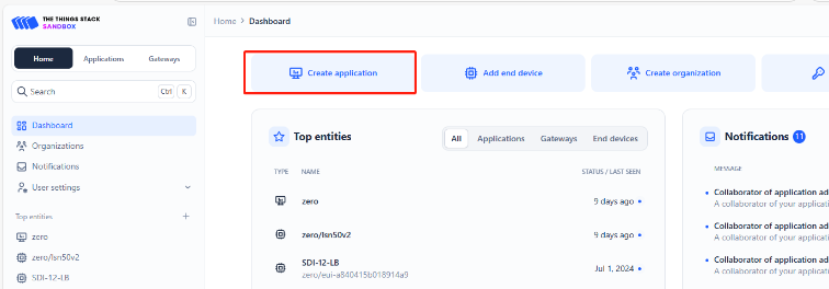
You can enter this key in the LoRaWAN Server portal. Below is TTN screen shot:
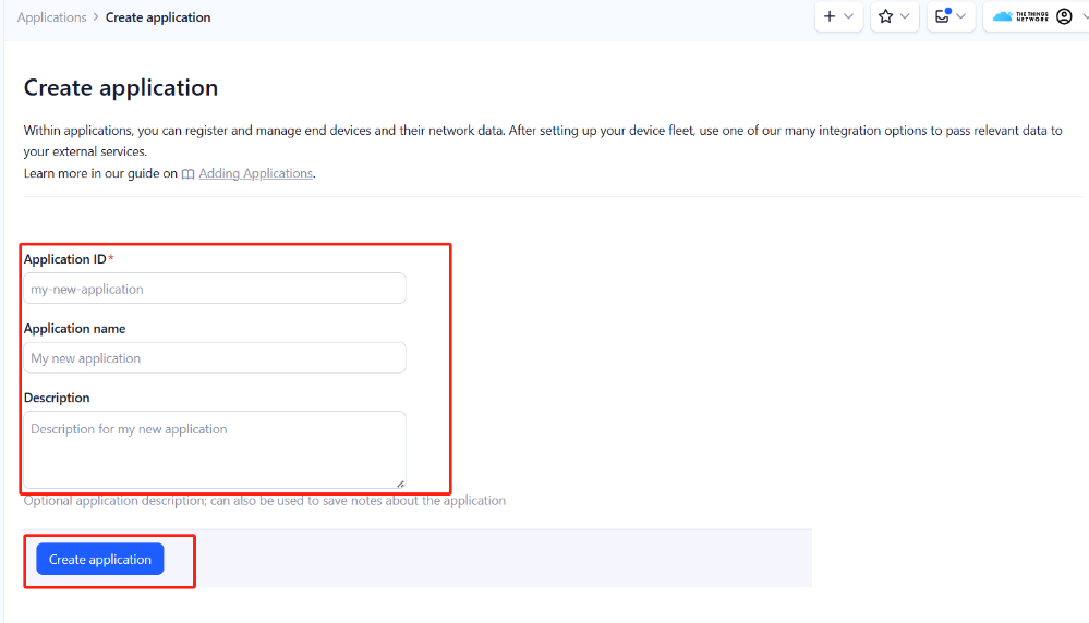
Create the application.
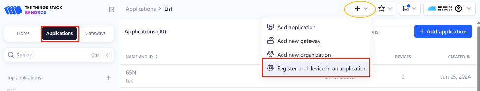
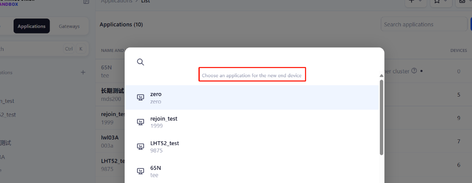
Add devices to the created Application.
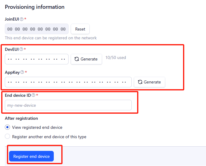
Enter end device specifics manually.
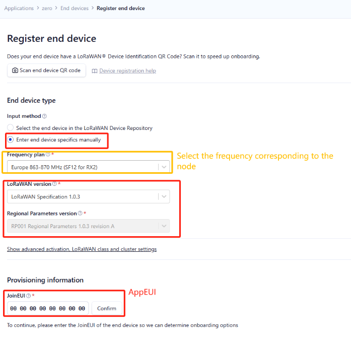
Add DevEUI and AppKey.
Customize a platform ID for the device.
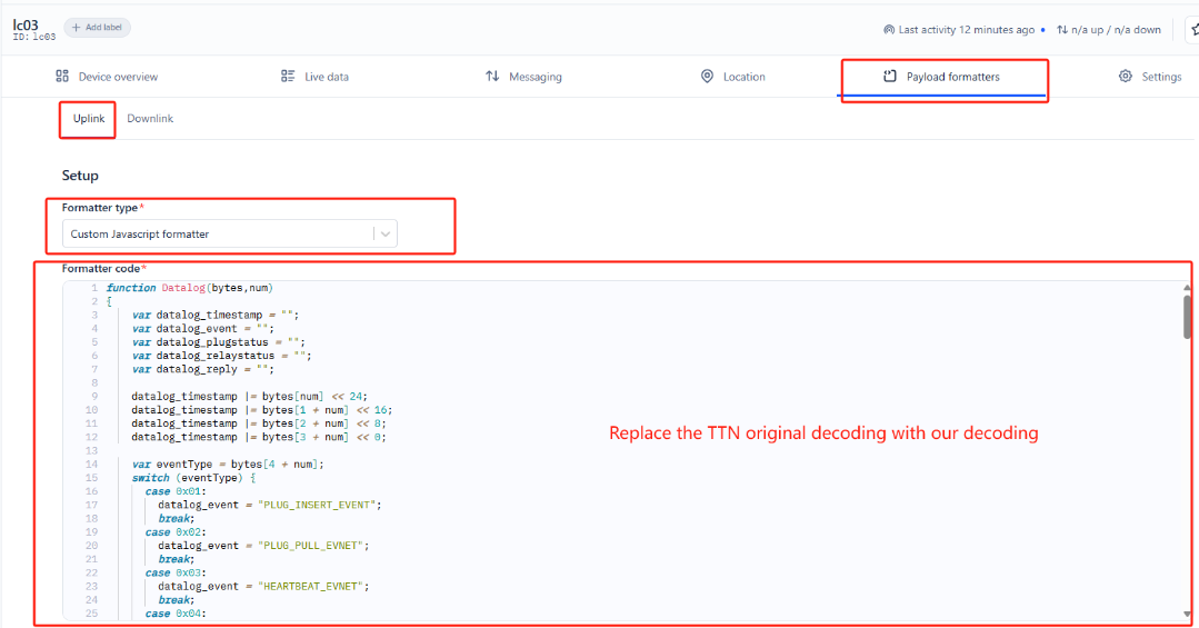
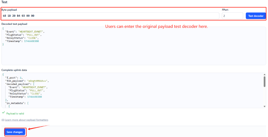
Step 2: Add decoder.
In TTN, user can add a custom payload so it shows friendly reading.
Click this link to get the decoder: https://github.com/dragino/dragino-end-node-decoder/tree/main/
Below is TTN screen shot:
Step 3: Activate on LC04
Press the reset button once to activate the LC04.
Red led will fast blink 5 times, device will enter bootloader mode for 5 seconds. And then start to JOIN LoRaWAN network. Red led will solidly turn on for 5 seconds after joined in network.
After join success, it will start to upload messages to TTN and you can see the messages in the panel.
2.3 Uplink Payload
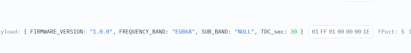
2.3.1 Device Status, FPORT=5
Users can use the downlink command(0x26 01) to ask LC04 to send device configure detail, include device configure status. LC04 will uplink a payload via FPort=5 to server.
The Payload format is as below.
| Device Status (FPORT=5) | |||||
| Size (bytes) | 1 | 1 | 2 | 3 | |
| Value | Frequency Band | Sub-band | Firmware Version | TDC |
Example parse in TTNv3
Frequency Band:
0x01: EU868
0x02: US915
0x03: IN865
0x04: AU915
0x05: KZ865
0x06: RU864
0x07: AS923
0x08: AS923-1
0x09: AS923-2
0x0a: AS923-3
0x0b: CN470
0x0c: EU433
0x0d: KR920
0x0e: MA869
Sub-Band:
AU915 and US915:value 0x00 ~ 0x08
CN470: value 0x0B ~ 0x0C
Other Bands: Always 0x00
Firmware Version: 0x0100, Means: v1.0.0 version
TDC:
0x00001E=30s
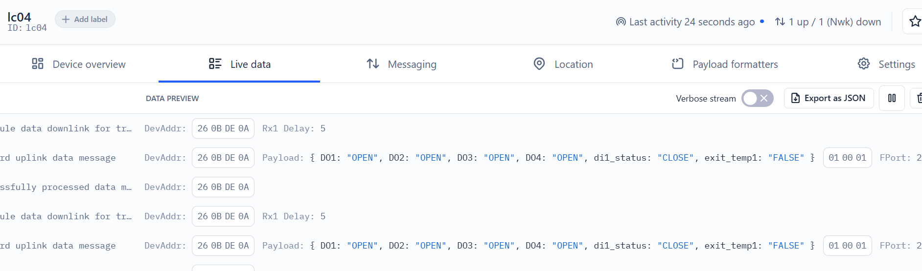
2.3.2 Sensor Data. FPORT=2
Sensor Data is uplink via FPORT=2
| Size(bytes) | 1 | 1 | 1 |
|---|---|---|---|
| Value | Meaningless | CTL_flags | exit_flag_status |
CTL_flags
Example:
0000=0x00 No ports open
0001=0x01 Port 1 open
0010=0x02 Port 2 open
0100=0x04 Port 3 open
1000=0x08 Port 4 open
exit_flag_status
Example:
di1_status is valid : 0x01
exit_temp1 is valid : 0x10
2.4 Payload Decoder file
In TTN, use can add a custom payload so it shows friendly reading
In the page Applications --> Payload Formats --> Custom --> decoder to add the decoder from:
https://github.com/dragino/dragino-end-node-decoder/tree/main
2.5 Datalog Feature
Datalog Feature is to ensure IoT Server can get all sampling data from Sensor even if the LoRaWAN network is down. For each sampling, LC04 will store the reading for future retrieving purposes.
2.5.1 Ways to get datalog via LoRaWAN
With the platform downlink 07 01, turn on the device to send None-ACK message function automatically, LC04 will wait for every upstream ACK, when there is no LoRaWAN network, LC04 will mark these records as non ack message and store the sensor data, and wait for the network to be restored (10s interval) to send all the messages.
a) LC04 will do an ACK check for data records sending to make sure every data arrive server.
b) When automatic sending of None-ACK messages is enabled, the LC04 will send data in CONFIRMED mode, but if an ACK is not received, the LC04 will not resend the packet, it will only mark it as a NONE-ACK message. On subsequent uplinks, if the LC04 receives an ACK, the LC04 will consider the network connected and resend all NONE-ACK messages.
2.5.2 Unix TimeStamp
LC04 uses Unix TimeStamp format based on
User can get this time from link: https://www.epochconverter.com/ :
Below is the converter example
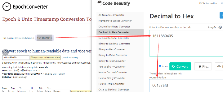
So, we can use downlink 3060137afd00 to set the current time 2021 – Jan -- 29 Friday 03:03:25
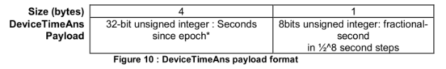
2.5.3 Set Device Time
Users need to run downlink command 28 01 to enable the synchronization time.
Once LC04 Joined LoRaWAN network, it will send the MAC command (DeviceTimeReq) and the server will reply with (DeviceTimeAns) to send the current time to LC04. If LC04 fails to get the time from the server, LC04 will use the internal time and wait for next time request (The default time is once every 10 days.).
Note: LoRaWAN Server need to support LoRaWAN v1.0.3(MAC v1.0.3) or higher to support this MAC command feature, Chirpstack,TTN V3 v3 and loriot support but TTN V3 v2 doesn't support. If server doesn't support this command, it will through away uplink packet with this command, so user will lose the packet with time request for TTN V3 v2 if when the automatic time synchronization function is turned on.
Downlink Command: 0x28
- Example: 0x28 01 // Automatic time synchronization Enabled
- Exampie: 0x28 00 // Automatic time synchronization Disable.
的的
2.6 Frequency Plans
The LC04 uses OTAA mode and below frequency plans by default. Each frequency band use different firmware, user update the firmware to the corresponding band for their country.
/docs/wiki/Configuration/end-node/frequency-band/
2.7 Firmware Change Log
**Firmware download link: **Dropbox - firmware
3. Configure LC04
3.1 Configure Methods
LC04 supports below configure method:
- LoRaWAN Downlink. Instruction for different platforms: See IoT LoRaWAN Server section.
3.2 General Commands
These commands are to configure:
- General system settings like: uplink interval.
- LoRaWAN protocol & radio related command.
They are same for all Dragino Devices which support DLWS-005 LoRaWAN Stack. These commands can be found on the wiki:
/docs/wiki/Configuration/end-node/at-commands-downlink/
3.3 Commands special design for LC04
These commands only valid for LC04, as below:
3.3.1 Set Transmit Interval Time
AT Command:
There is no AT command to set TDC time.
Feature: Change LoRaWAN End Node Transmit Interval.
Downlink Command: 0x01
Format: Command Code (0x01) followed by 3 bytes time value.
If the downlink payload=0100003C, it means set the END Node's Transmit Interval to 0x00003C=60(S), while type code is 01.
- Example 1: Downlink Payload: 0100001E // Set Transmit Interval (TDC) = 30 seconds
- Example 2: Downlink Payload: 0100003C // Set Transmit Interval (TDC) = 60 seconds
3.3.2 Get Device Status
Send a LoRaWAN downlink to ask device send Alarm settings.
Downlink Payload: 0x26 01
Sensor will upload Device Status via FPORT=5. See payload section for detail.
3.3.3 Clear Flash Record
AT Command:
No AT command to control relay enable or disable
Feature: Clear flash storage for data log feature.
Downlink Command: 0x08
- Example: 0x0801 // Clear all saved data in flash.
3.3.4 Relay enable or disable
AT Command:
There is no AT Command to control the Relay Output
Feature: Controls the turning on and off of appliances plugged into the socket
Downlink Command: 0x06
- Example: 0x06 01 // Relay Enabled.
- Exampie: 0x06 00 // Relay Disable.
3.3.5 Relay -- Control Relay Output time

Feature: Controls the relay output time.
AT Command:
There is no AT Command to control the Relay Output
Downlink Payload (prefix 0xB0):
**0xB0 aa bb cc dd ** // Sets relays with time control
First byte : Type code (0xb0)
Control Method and Ports status:
Type 0xb0, function is to control CTL closing or opening, and an uplink packet will be reported immediately after the change is completed.
Third byte (aa): CTL1, 01 is open, 00 is close, and other values do not respond.
Third byte (bb): CTL2, 01 is open, 00 is close, and other values do not respond.
Third byte (cc): CTL3, 01 is open, 00 is close, and other values do not respond.
Third byte (dd): CTL4, 01 is open, 00 is close, and other values do not respond.
Example:
B0 01 01 01 01 controls 4 CTLs to open
B0 00 00 00 00 controls 4 CTLs to close
B0 01 01 02 02 controls the 1st, 2nd to Open, and the others do not.
respond.
3.3.6 Relay -- Control Relay Output with Time Delay
AT Command:
There is no AT command to control the Relay Output with time delay. This feature requires LoRaWAN downlink command.
Feature:
Control the relay output with a timed delay. After the specified delay period, the relay state will return to its original state or flip, and an uplink packet will be reported immediately after the state change.
Downlink Payload Prefix: 0xB1
A. 7-byte Format: Control Single CTL
| Byte | Description |
|---|---|
| 0 | Command type: 0xB1 (Relay Control with Delay) |
| 1 | Mode: 0x00 = Flip after delay, 0x01 = Return to original state after delay |
| 2 | CTL Number: 1~4 |
| 3 | State: 0x00 = Open, 0x01 = Close, Other = No response |
| 4~6 | Delay Time (seconds), MSB first (Big-endian) |
7-byte Format Examples:
Example 1: Control CTL1 to Open with 2-second delay, then return to original state.
Downlink Payload: B1 01 01 00 00 00 02
Meaning: CTL1 will open for 2 seconds, then return to its original state.
Example 2: Control DO3 to Flip (toggle) with 2-second delay.
Downlink Payload: B1 00 04 01 00 00 02
Meaning: CTL2 will change state (close if was open, open if was close) for 2 seconds, then flip back.
B. 8-byte Format: Control Multiple CTLs Simultaneously
| Byte | Description |
|---|---|
| 0 | Command type: 0xB1 (Relay Control with Delay) |
| 1 | Mode: 0x00 = Flip after delay, 0x01 = Return to original state after delay |
| 2 | 0x00 (Fixed value for multi-CTL control) |
| 3 | CTL Bitmap: Bit0=CTL1, Bit1=CTL2, Bit2=CTL3, Bit3=CTL4 (1=control, 0=skip) |
| 4 | State: 0x00 = Open all selected CTLs, 0x01 = Close all selected CTLs, Other = No response |
| 5~7 | Delay Time (seconds), MSB first (Big-endian) |
8-byte Format Examples:
Example 1: Control All CTLs (1-4) to Open with 2-second delay, then return to original state.
Downlink Payload: B1 01 00 0F 00 00 00 02
Meaning: All 4 CTLs will open for 2 seconds, then return to their original states.
Example 2: Control All CTLs to Flip (toggle) with 2-second delay.
Downlink Payload: B1 00 00 0F 01 00 00 02
Meaning: All 4 CTLs will toggle their states for 2 seconds, then toggle back.
Example 3: Control CTL1 & CTL2 to Open with 2-second delay, then return to original state.
Downlink Payload: B1 01 00 03 00 00 00 02
Meaning: CTL1 and CTL2 will open for 2 seconds, then return to their original states.
Example 4: Control CTL1 & CTL2 to Flip (toggle) with 2-second delay.
Downlink Payload: B1 00 00 03 01 00 00 02
Meaning: CTL1 and CTL2 will toggle their states for 2 seconds, then toggle back.
CTL Bitmap Reference (Byte 3 in 8-byte format):
| Bitmap Value | CTLs Controlled |
|---|---|
| 0x01 | CTL1 only |
| 0x02 | CTL2 only |
| 0x03 | CTL1 & CTL2 |
| 0x0F | CTL1, CTL2, CTL3 & CTL4 (All) |
3.3.7 Confirmed Mode
AT Command:
There is no AT command to control whether Confirmed mode is enabled or disabled.
Feature: Mode for sending data for which acknowledgment was not received
Downlink Command: 0x06
- Example: 0x07 01 // Confirmed Mode enabled.
- Exampie: 0x07 00 // Confirmed Mode Disable.
3.3.8 Set the time synchronization interval
Feature: Set how often to perform time synchronization.(default is 10 days, Unit: days)
Downlink Command: 0x28
- Example: 0x28 01 // Synchronize once a day
- Exampie: 0x28 03 // Synchronize once every three days
4. OTA Firmware update
User can change firmware LC04 to:
- Change Frequency band/ region.
- Update with new features.
- Fix bugs.
Firmware and changelog can be downloaded from : Firmware download link
Methods to Update Firmware:
- (Recommended way) OTA firmware update via wireless: Firmware OTA Update for LoRaWAN End Node
5. Order Info
Part Number: LC04-XX
XX: The default frequency band
-
AS923: LoRaWAN AS923 band
-
AU915: LoRaWAN AU915 band
-
EU433: LoRaWAN EU433 band
-
EU868: LoRaWAN EU868 band
-
KR920: LoRaWAN KR920 band
-
US915: LoRaWAN US915 band
-
IN865: LoRaWAN IN865 band
-
CN470: LoRaWAN CN470 band
6. Packing Info
Package Includes:
- LC04 LoRaWAN 4 Channel low voltage control cable
Dimension and weight:
-
Package Size / pcs : 190x50x30mm
-
Weight / pcs : 95g
7. Support
-
Support is provided Monday to Friday, from 09:00 to 18:00 GMT+8. Due to different timezones we cannot offer live support. However, your questions will be answered as soon as possible in the before-mentioned schedule.
-
Provide as much information as possible regarding your enquiry (product models, accurately describe your problem and steps to replicate it etc) and send a mail to Support@dragino.cc.
0