LA66 LoRaWAN Module
1. LA66 LoRaWAN Module
1.1 What is LA66 LoRaWAN Module
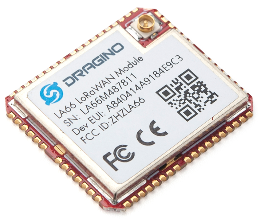
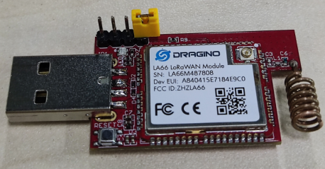
Dragino LA66 is a small wireless LoRaWAN module that offers a very compelling mix of long-range, low power consumption, and secure data transmission. It is designed to facilitate developers to quickly deploy industrial-level LoRaWAN and IoT solutions. It helps users to turn the idea into a practical application and make the Internet of Things a reality. It is easy to create and connect your things everywhere.
LA66 is a ready-to-use module that includes the LoRaWAN v1.0.3 protocol. The LoRaWAN stack used in LA66 is used in more than 1 million LoRaWAN End Devices deployed world widely. This mature LoRaWAN stack greatly reduces the risk to make stable LoRaWAN Sensors to support different LoRaWAN servers and different countries' standards. External MCU can use AT command to call LA66 and start to transmit data via the LoRaWAN protocol.
Each LA66 module includes a world-unique OTAA key for LoRaWAN registration.
Besides the support of the LoRaWAN protocol, LA66 also supports open-source peer-to-peer LoRa Protocol for the none-LoRaWAN application.
LA66 is equipped with TCXO crystal which ensures the module can achieve stable performance in extreme temperatures.
1.2 Features
- Support LoRaWAN v1.0.3 protocol
- Support peer-to-peer protocol
- TCXO crystal to ensure RF performance on low temperature
- SMD Antenna pad and i-pex antenna connector
- Available in different frequency LoRaWAN frequency bands.
- World-wide unique OTAA keys.
- AT Command via UART-TTL interface
- Firmware upgradable via UART interface
- Ultra-long RF range
1.3 Specification
- CPU: 32-bit 48 MHz
- Flash: 256KB
- RAM: 64KB
- Input Power Range: 1.8v ~ 3.7v
- Power Consumption: < 4uA.
- Frequency Range: 150 MHz ~ 960 MHz
- Maximum Power +22 dBm constant RF output
- High sensitivity: -148 dBm
- Temperature:
- Storage: -55 ~ +125℃
- Operating: -40 ~ +85℃
- Humidity:
- Storage: 5 ~ 95% (Non-Condensing)
- Operating: 10 ~ 95% (Non-Condensing)
- LoRa Tx Current: <90 mA at +17 dBm, 108 mA at +22 dBm
- LoRa Rx current: <9 mA
- I/O Voltage: 3.3v
1.4 AT Command
AT Command is valid over Main TXD and Main RXD. Serial Baud Rate is 9600. AT commands can be found in AT Command documents.
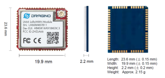
1.5 Dimension
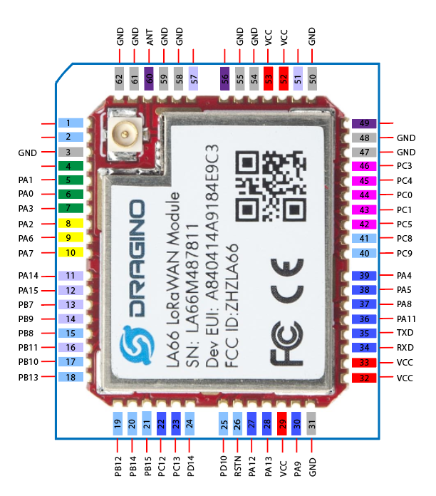
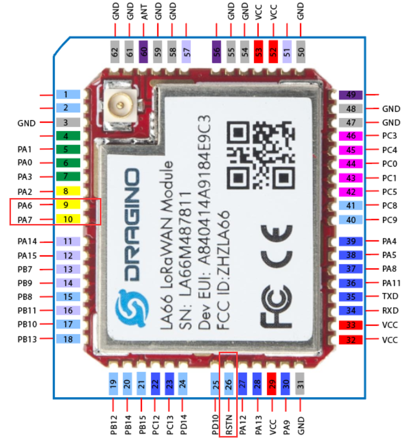
1.6 Pin Mapping
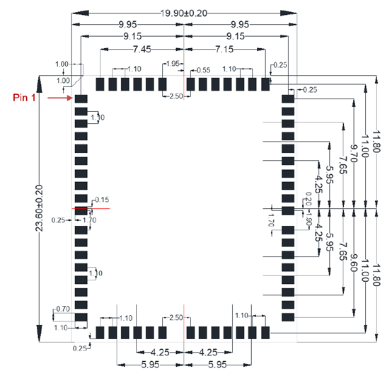
1.7 Land Pattern
2. FAQ
2.1 Where to find examples of how to use LA66?
Below products are made by LA66. User can use their examples as reference:
2.2 How to Compile Source Code for LA66?
Compile and Upload Code to ASR6601 Platform:Instruction
2.3 Can i use LA66 module's internal I/O without external MCU, So to save product cost?
Yes, this is possible, user can refer the source code from ASR to get examples for how to its I/O Interfaces.
2.4 Where to find Peer-to-Peer firmware of LA66?
Instruction for LA66 Peer to Peer firmware : Instruction
2.5 How can i use J-LInk to debug LA66?
The steps are as follows: 1. Install J-Link software from
https://www.segger.com/downloads/jlink/
2. Expose PA6 / PA7 / RSTN of LA66.
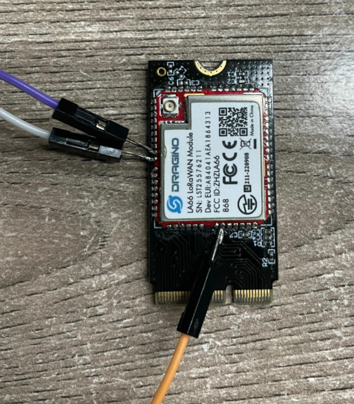
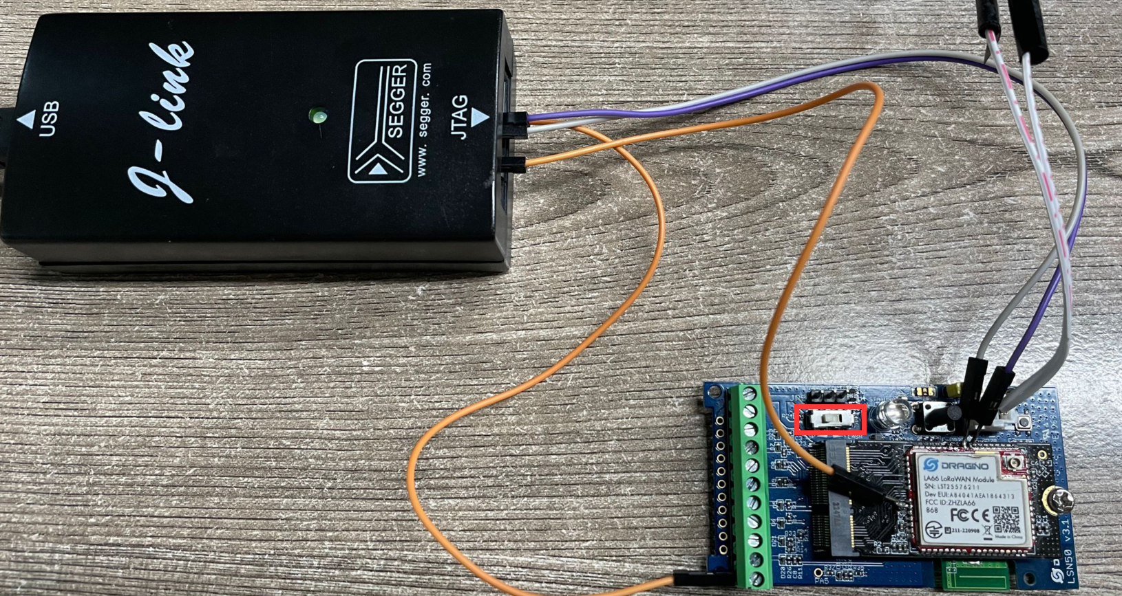
3. Connect JLINK, and switch mother board SW1 to ISP. Wire connection as below: LA66 PA6 < -- > JLINK SWDIO (Pin 7) LA66 PA7 < -- > JLINK SWCLK (Pin 9) LA66 RSTN < -- > JLINK RESET (Pin 15) LA66 GND < -- > JLINK GND (Pin 8)
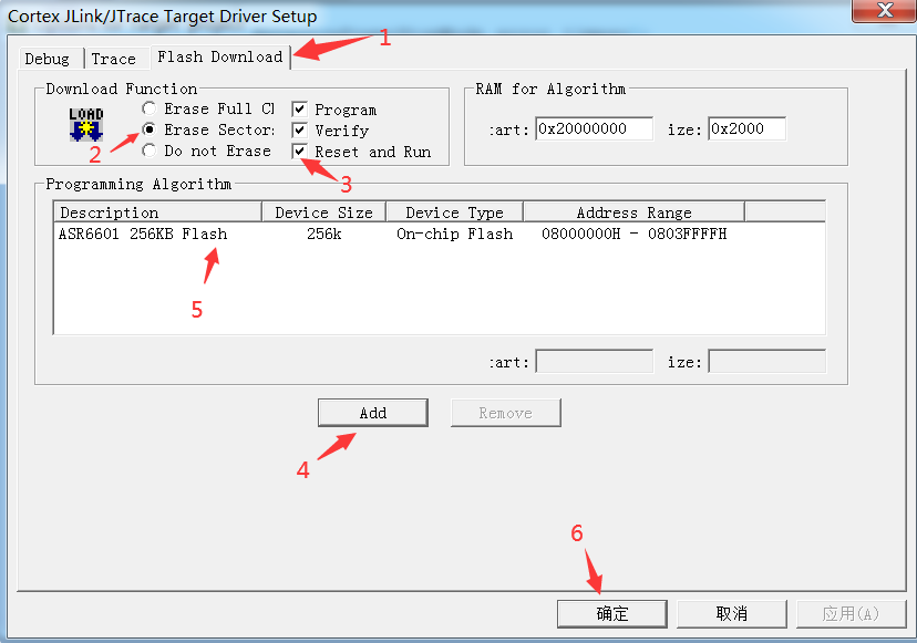
4. Copy \SN50v3\tools\FLM\ASR6601.FLM to \Keil\ARM\ Flash\
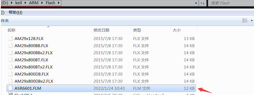
Add ASR6601 256KB Flash to Flash Download
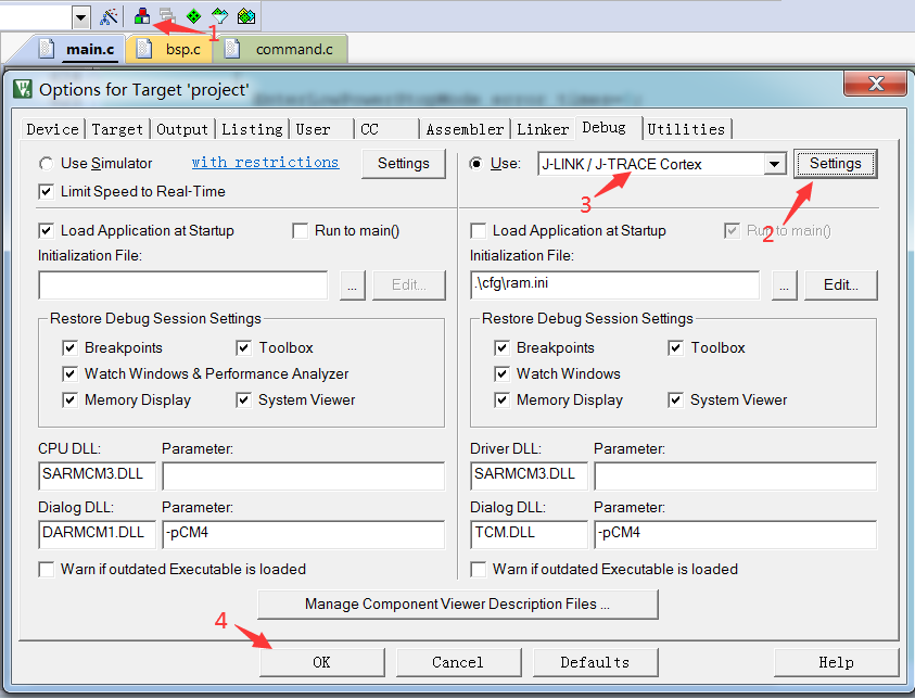
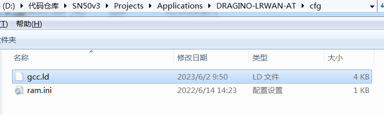
5. Modify \SN50v3\Projects\Applications\DRAGINO-LRWAN-AT\cfg\gcc.ld, to 0x08000000.
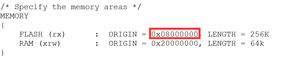
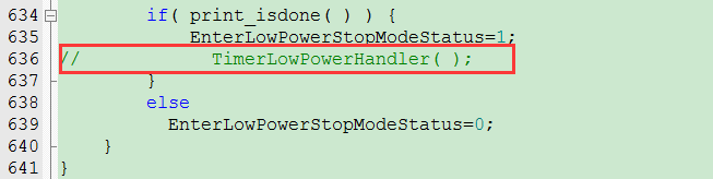
Note: After debug, user should change the Flash address back to 0x0800D000, and upload the OTA bootloader to LA66. Otherwise, the compiled program doesn't support OTA update. 6. Comment the low power function in main.c.
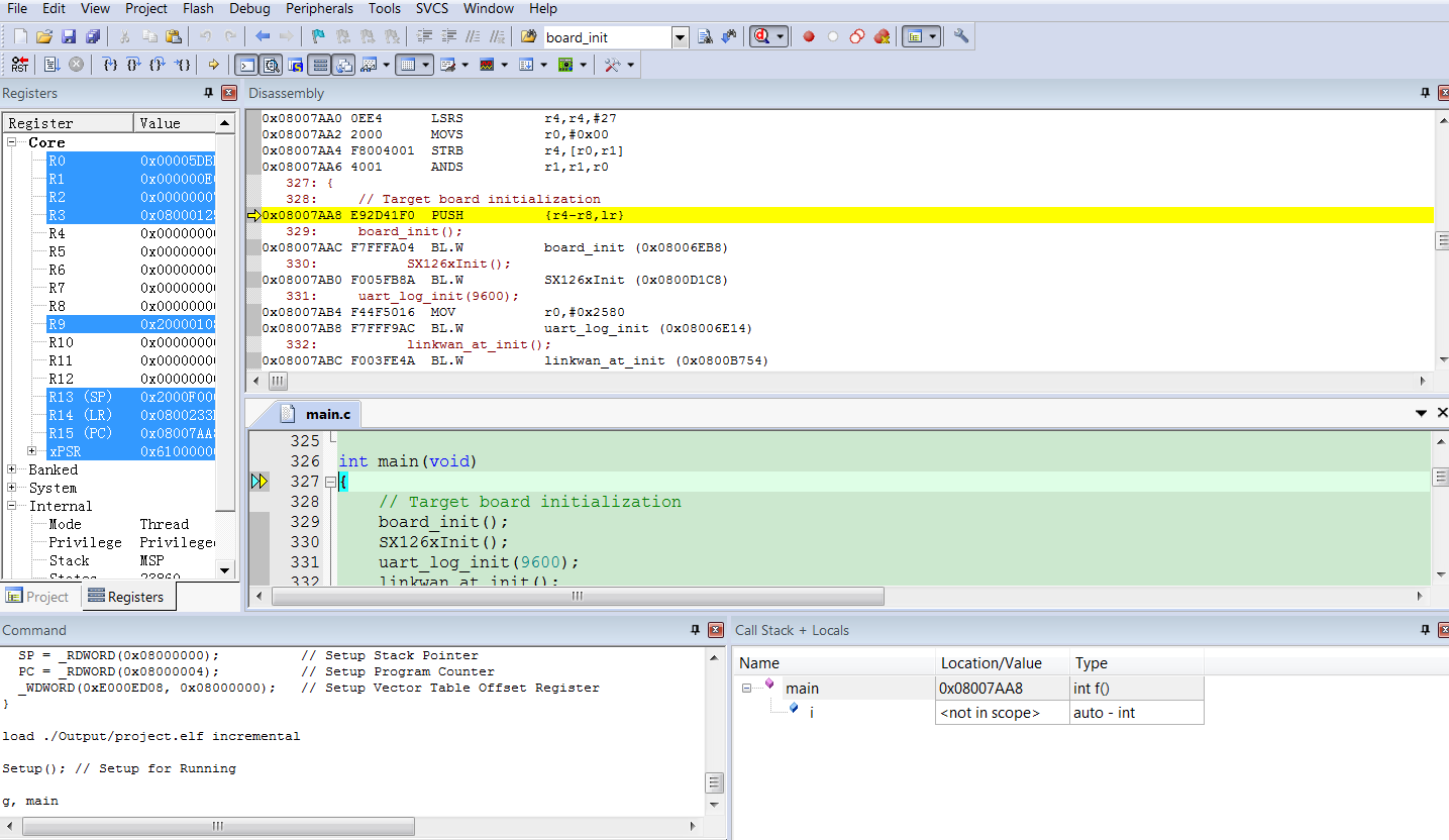
Click Debug mode to debug.
3. Order Info
Part Number: LA66-XXX XXX: The default frequency band
- AS923: LoRaWAN AS923 band
- AU915: LoRaWAN AU915 band
- EU433: LoRaWAN EU433 band
- EU868: LoRaWAN EU868 band
- KR920: LoRaWAN KR920 band
- US915: LoRaWAN US915 band
- IN865: LoRaWAN IN865 band
- CN470: LoRaWAN CN470 band
- PP: Peer to Peer LoRa Protocol
4. FCC Statement
FCC Caution:
Any Changes or modifications not expressly approved by the party responsible for compliance could void the user's authority to operate the equipment.
This device complies with part 15 of the FCC Rules. Operation is subject to the following two conditions: (1) This device may not cause harmful interference, and (2) this device must accept any interference received, including interference that may cause undesired operation.
IMPORTANT NOTE: Note: This equipment has been tested and found to comply with the limits for a Class B digital device, pursuant to part 15 of the FCC Rules. These limits are designed to provide reasonable protection against harmful interference in a residential installation. This equipment generates, uses and can radiate radio frequency energy and, if not installed and used in accordance with the instructions, may cause harmful interference to radio communications. However, there is no guarantee that interference will not occur in a particular installation. If this equipment does cause harmful interference to radio or television reception, which can be determined by turning the equipment off and on, the user is encouraged to try to correct the interference by one or more of the following measures:
—Reorient or relocate the receiving antenna.
—Increase the separation between the equipment and receiver.
—Connect the equipment into an outlet on a circuit different from that to which the receiver is connected.
—Consult the dealer or an experienced radio/TV technician for help.
**FCC Radiation Exposure Statement: **
This equipment complies with FCC radiation exposure limits set forth for an uncontrolled environment.This equipment should be installed and operated with minimum distance 20cm between the radiator& your body.
0
Compile and Upload Code to ASR6601 Platform
1. Instruction for Windows OS Platform
Step 1:Install MSYS2
Download MSYS2 and Install

Step 2:Open MSYS2

Install related software: pacman -S git vim make unzip python python-pip
Use pip to install pyserial:pip install pyserial configparser


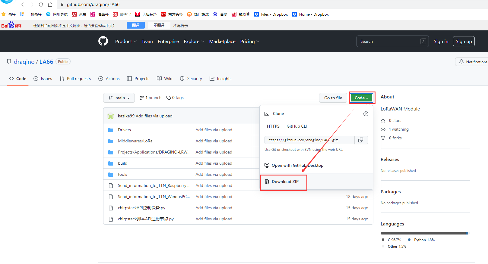
Step 3:Get LA66 SDK. Step 1: Download LA66 code. There are two alternatives, you can use one of them.
-
ASR Official SDK. Include ping pong example
-
GitHub - dragino/LA66: LoRaWAN Module (Dragino SDK for LA66, LoRaWAN version).
Step 2: Downloads | GNU Arm Embedded Toolchain Downloads – Arm Developer
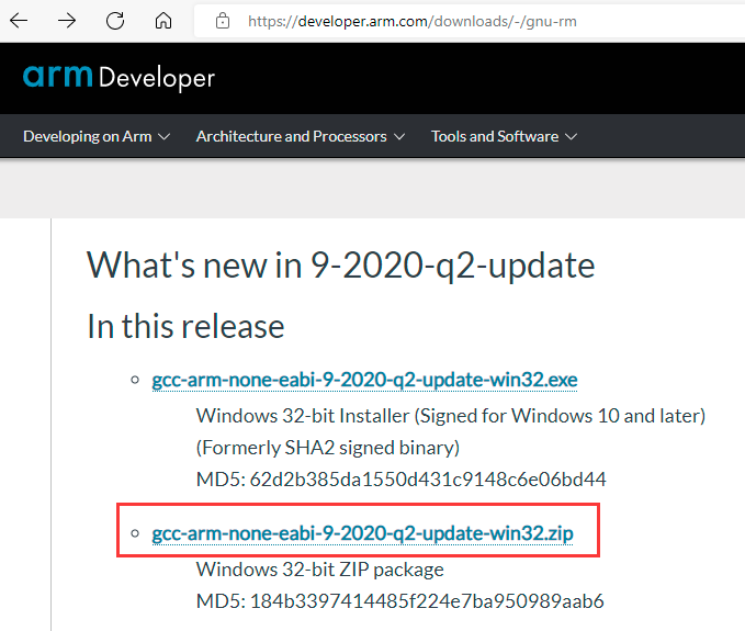
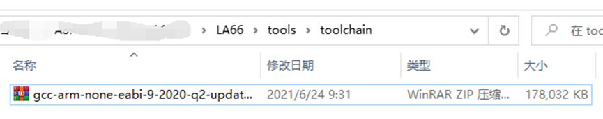
Step 3: Copy the file downloaded in step 2 to the folder directory of .../LA66/tools/toolchain in step 1.
Step 4:Connect your LA66 to PC via USB TTL.
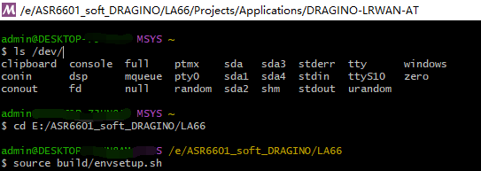
Step 5:Check USB Port ls /dev/

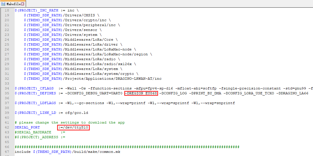
Step 6:Open Makefile File, Modify Region and USB Port

Step 7:Use Make to compile
Open Directory cd E: /ASR6601_soft_DRAGINO/LA66
source build/envsetup.sh
cd Projects/Applications/DRAGINO-LRWAN-AT
make
make flash

Step 8:Uplink Image to LA66
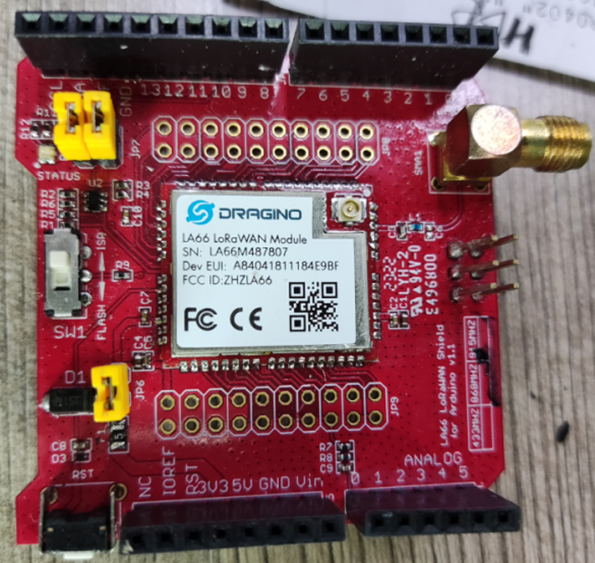
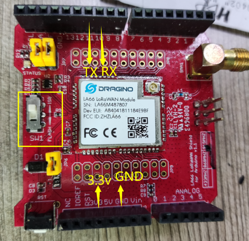
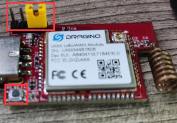
LA66 LoRaWAN shield:
Connection: Connect the Jump cap 10 <-> USB TTL RX 11 <-> USB TTL TX GND <-> USB TTL GND 3V3 <-> USB TTL 3.3v Switch SW1 to ISP Press the RST key
Put USB LoRaWAN Adapter into Program Mode, and press reset
Run make flash
![]()

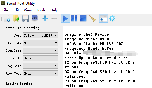
Wait for update finish, remove program jumper and press reset
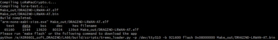
Below is the serial output after update success.
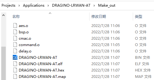
Example for output files of Make
2. Instruction for Keil
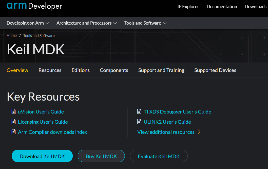
Step 1:Install and buy Keil MDK
Download Keil and Install
Step 2:Get LA66 SDK Step 1: Download LA66 code. There are two alternatives, you can use one of them.
-
ASR Official SDK. Include ping pong example
-
GitHub - dragino/LA66: LoRaWAN Module (Dragino SDK for LA66, LoRaWAN version).
Step 2: Downloads | GNU Arm Embedded Toolchain Downloads – Arm Developer
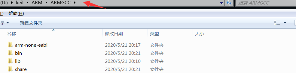
Step 3: Unzip the file downloaded in step 2 to the root directory of keil. As shown below:
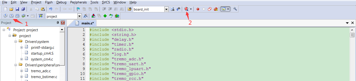
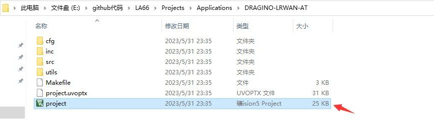
Step 3:Add firmware library to keil Step 1: Open the keil project.
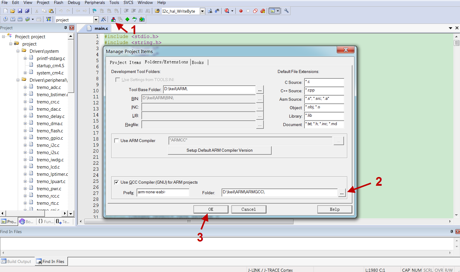
Step 2: Add firmware library.
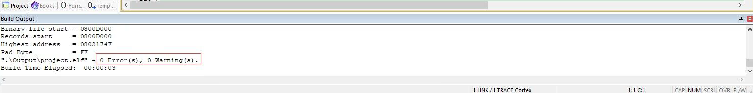
Step 3: Compile successfully.
Step 4:Download firmware
UART Access for LoRa ST v4 base model
0