LA66 LoRaWAN Shield
1. LA66 LoRaWAN Shield
1.1 Overview
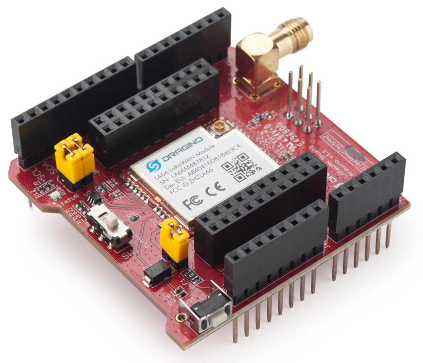
LA66 LoRaWAN Shield is the Arduino shield base on LA66. Users can use LA66 LoRaWAN Shield to rapidly add LoRaWAN or peer-to-peer LoRa wireless function to Arduino projects.
LA66 is a ready-to-use module that includes the LoRaWAN v1.0.3 protocol. The LoRaWAN stack used in LA66 is used in more than 1 million LoRaWAN End Devices deployed world widely. This mature LoRaWAN stack greatly reduces the risk to make stable LoRaWAN Sensors to support different LoRaWAN servers and different countries' standards. External MCU can use AT command to call LA66 and start to transmit data via the LoRaWAN protocol.
Each LA66 module includes a world-unique OTAA key for LoRaWAN registration.
Besides the support of the LoRaWAN protocol, LA66 also supports open-source peer-to-peer LoRa Protocol for the none-LoRaWAN application.
LA66 is equipped with TCXO crystal which ensures the module can achieve stable performance in extreme temperatures.
1.2 Features
- Arduino Shield base on LA66 LoRaWAN module
- Support LoRaWAN v1.0.3 protocol
- Support peer-to-peer protocol
- TCXO crystal to ensure RF performance on low temperature
- SMA connector
- Available in different frequency LoRaWAN frequency bands.
- World-wide unique OTAA keys.
- AT Command via UART-TTL interface
- Firmware upgradable via UART interface
- Ultra-long RF range
1.3 Specification
- CPU: 32-bit 48 MHz
- Flash: 256KB
- RAM: 64KB
- Input Power Range: 1.8v ~ 3.7v
- Power Consumption: < 4uA.
- Frequency Range: 150 MHz ~ 960 MHz
- Maximum Power +22 dBm constant RF output
- High sensitivity: -148 dBm
- Temperature:
- Storage: -55 ~ +125℃
- Operating: -40 ~ +85℃
- Humidity:
- Storage: 5 ~ 95% (Non-Condensing)
- Operating: 10 ~ 95% (Non-Condensing)
- LoRa Tx Current: <90 mA at +17 dBm, 108 mA at +22 dBm
- LoRa Rx current: <9 mA
- I/O Voltage: 3.3v
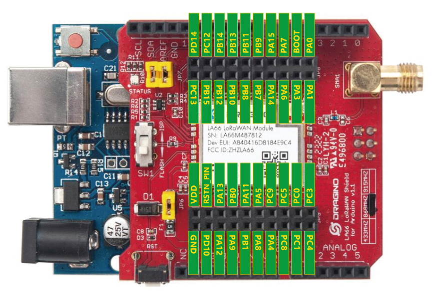
1.4 Pin Mapping & LED
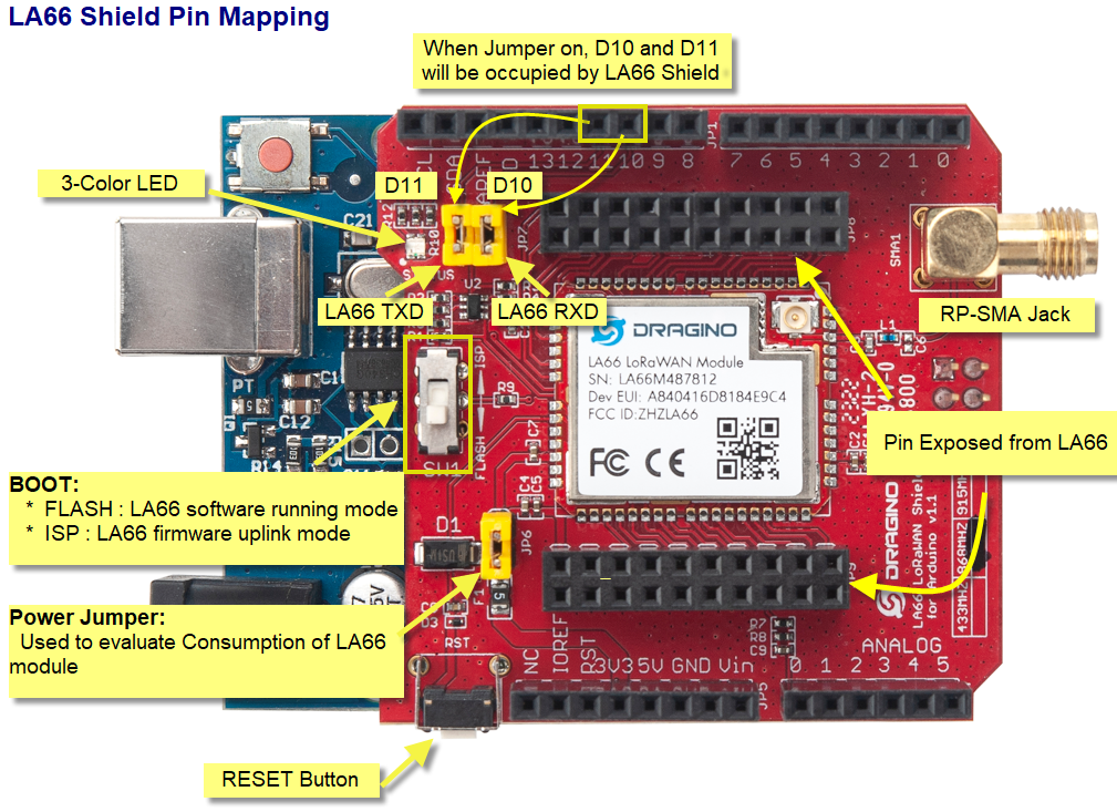
1. The LED lights up red when there is an upstream data packet
2. When the network is successfully connected, the green light will be on for 5 seconds
3. Purple light on when receiving downlink data packets
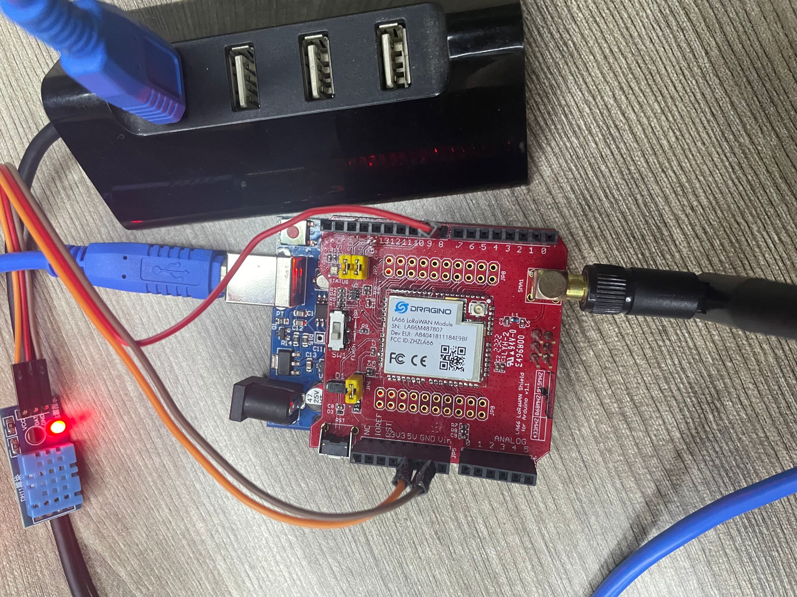
1.5 Example: Use AT Command to communicate with LA66 module via Arduino UNO.
Show connection diagram:
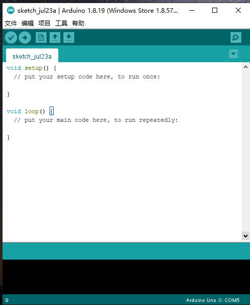
1. open Arduino IDE
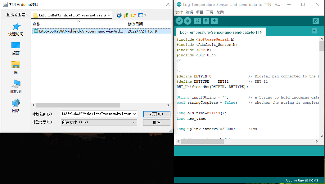
2. Open project
LA66-LoRaWAN-shield-AT-command-via-Arduino-UNO source code link: https://www.dropbox.com/sh/hgtycj0go4tka2r/AAACRRIRriMAudB2m3ThH7Sba?dl=0
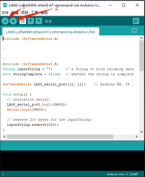
3. Click the button marked 1 in the figure to compile, and after the compilation is complete, click the button marked 2 in the figure to upload
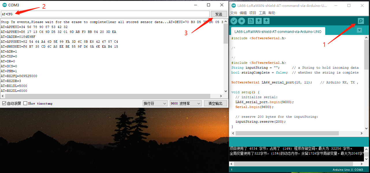
4. After the upload is successful, open the serial port monitoring and send the AT command
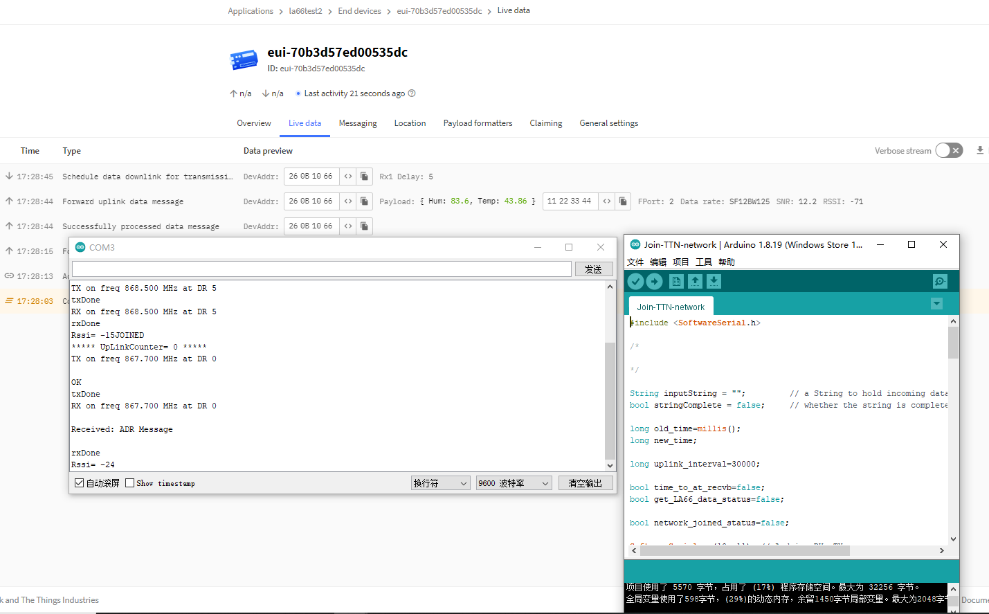
1.6 Example: Join TTN network and send an uplink message, get downlink message.
1. Open project
Join-TTN-network source code link: https://www.dropbox.com/sh/hgtycj0go4tka2r/AAACRRIRriMAudB2m3ThH7Sba?dl=0
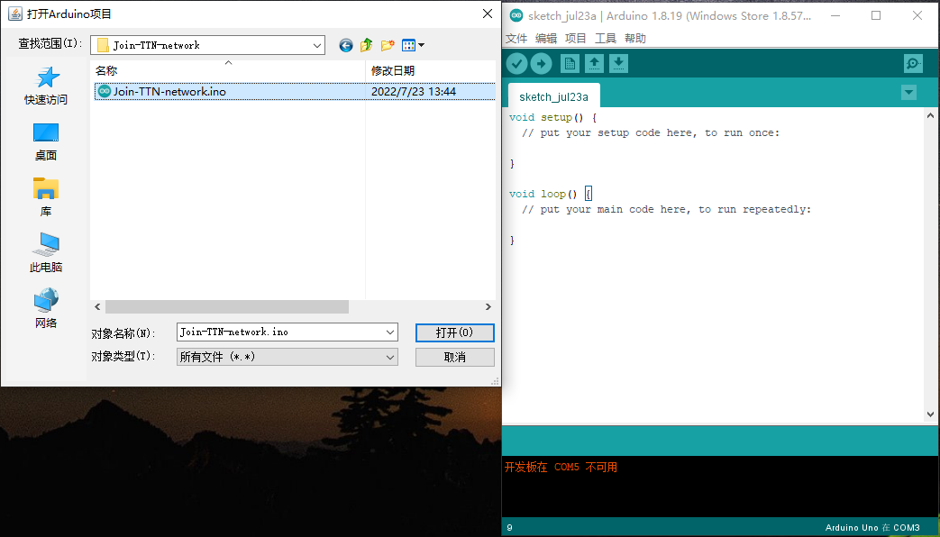
2. Same steps as 1.5,after opening the serial port monitoring, it will automatically connect to the network and send packets
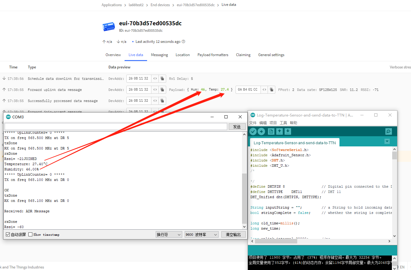
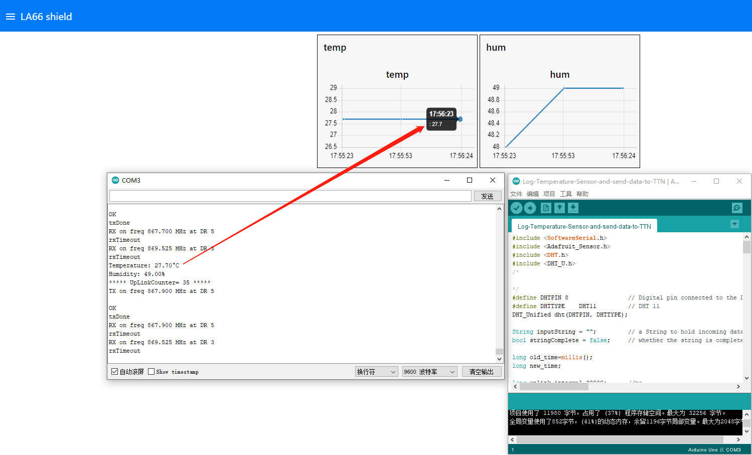
1.7 Example: Log Temperature Sensor(DHT11) and send data to TTN, show it in Node-RED.
1. Open project
Log-Temperature-Sensor-and-send-data-to-TTN source code link: https://www.dropbox.com/sh/hgtycj0go4tka2r/AAACRRIRriMAudB2m3ThH7Sba?dl=0
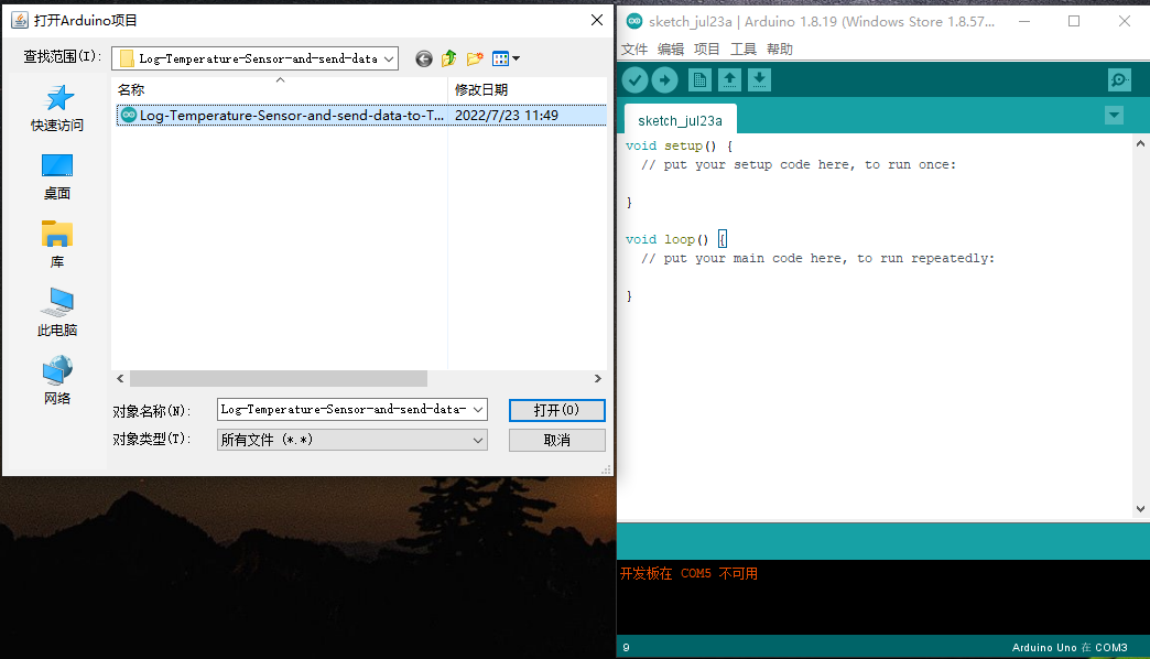
2. Same steps as 2.5,after opening the serial port monitoring, it will automatically connect to the network and send packets
3. Integration into Node-red via TTNV3
For the usage of Node-RED, please refer to: http:///docs/wiki/iot-lorawan-server/application-server/node-red/
1.8 Example: How to join helium
1. Create a new device.
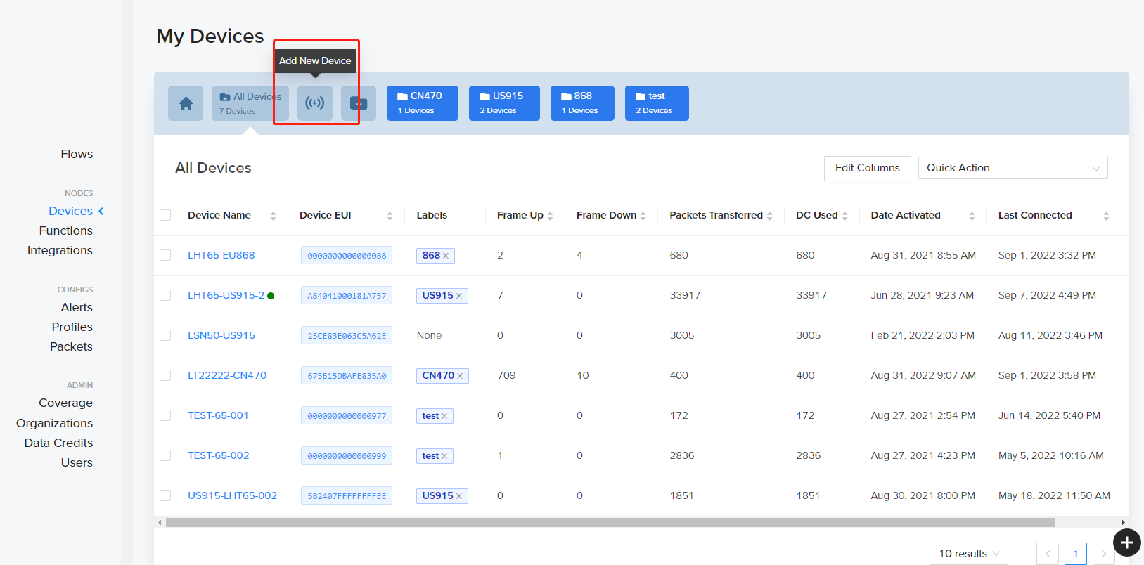
2. Save the device after filling in the necessary information.
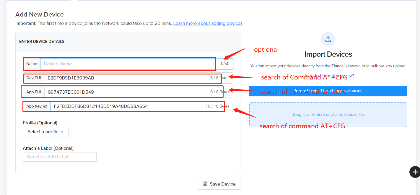
3. Use AT commands.
4. Use command AT+CFGto get device configuration
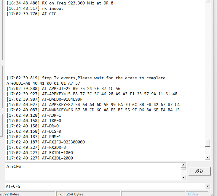
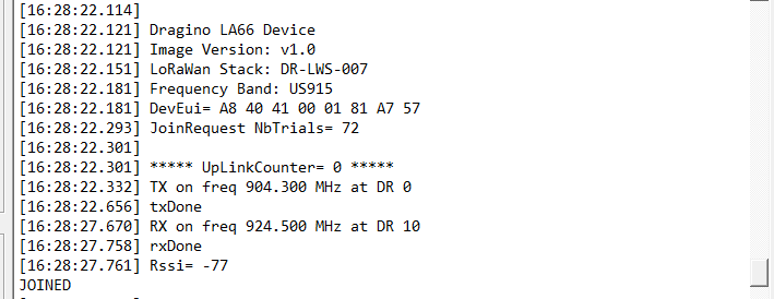
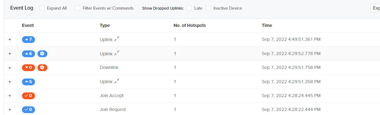
5. Network successfully.
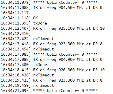
6. Send uplink using command
![]()
1.9 Upgrade Firmware of LA66 LoRaWAN Shield
1.9.1 Items needed for update
- LA66 LoRaWAN Shield
- Arduino
- USB TO TTL Adapter
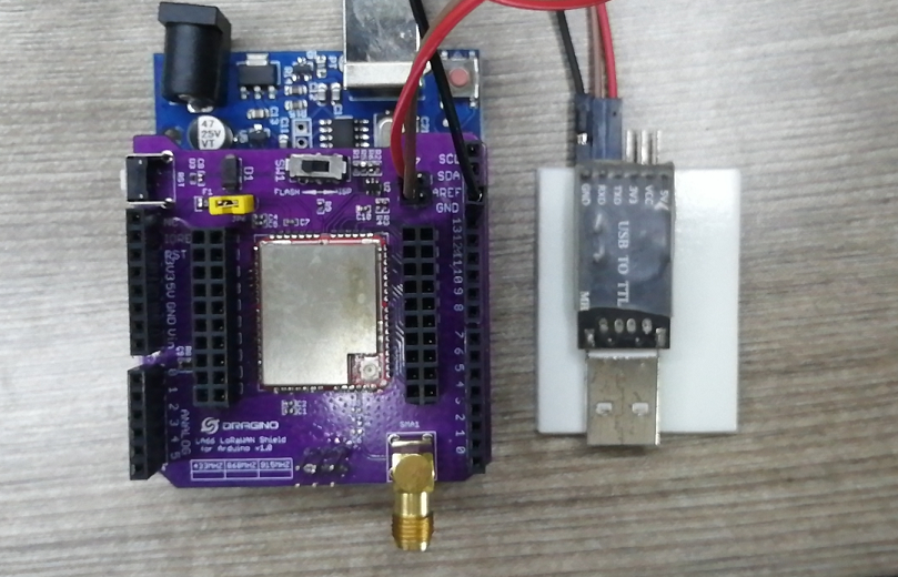
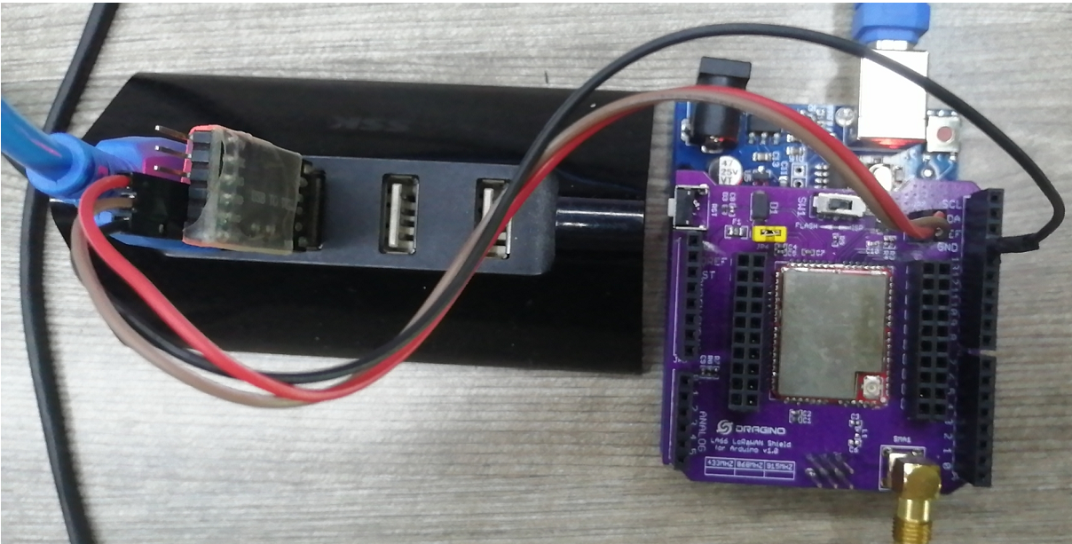
1.9.2 Connection
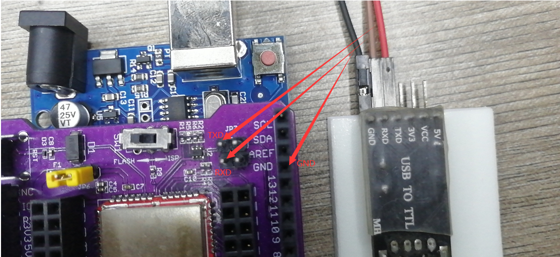
LA66 LoRaWAN Shield <-> USB TTL GND <-> GND TXD <-> TXD RXD <-> RXD
Put a jumper cap on JP6 of LA66 LoRaWAN Shield. ( the jumper is to power on LA66 module)
Connect USB TTL Adapter to PC after connecting the wires
1.9.3 Upgrade steps
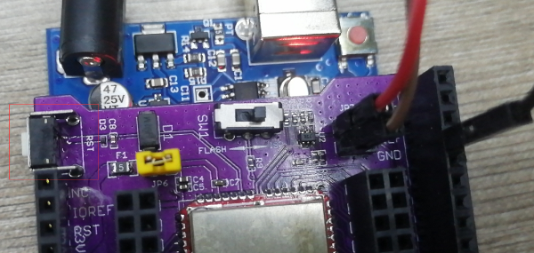
1. Switch SW1 to put in ISP position
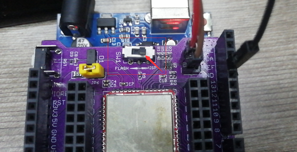
2. Press the RST switch once
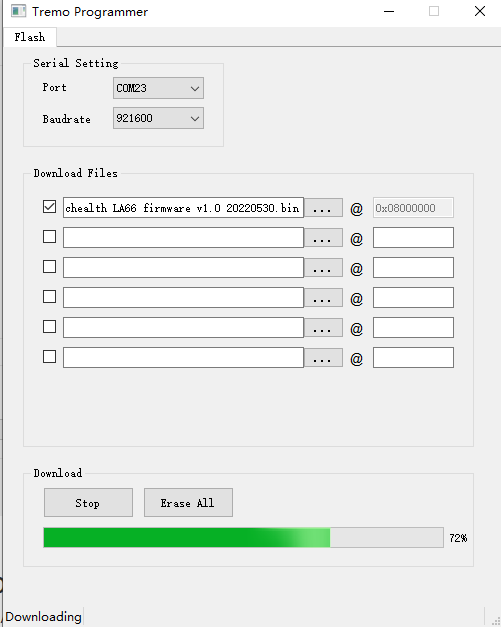
3. Open the Upgrade tool (Tremo Programmer) in PC and Upgrade 1. Software download link: https://www.dropbox.com/sh/j0qyc7a9ejit7jk/AACtx2tK4gEv6YFXMIVUM4dLa?dl=0

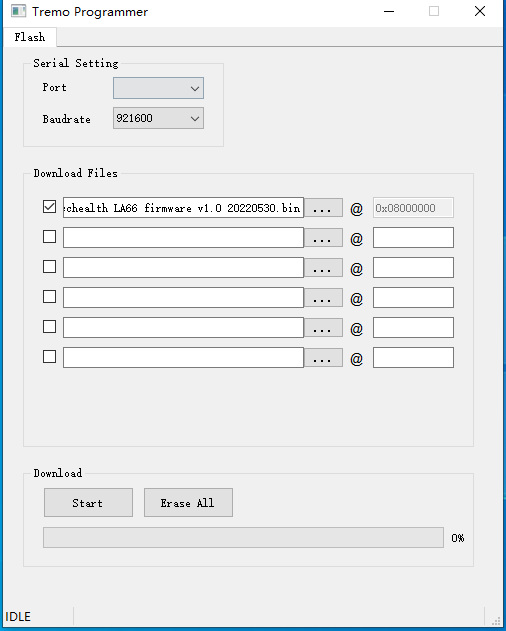
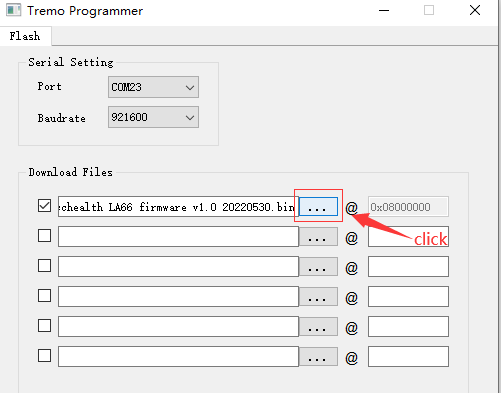
2. Select the COM port corresponding to USB TTL

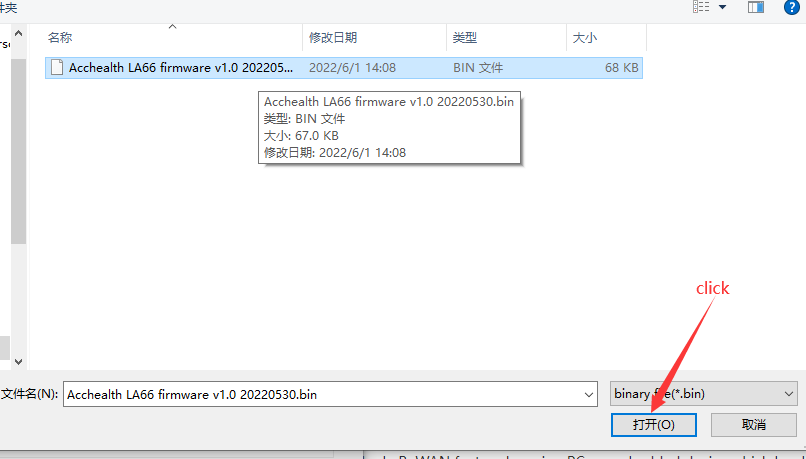
3. Select the bin file to burn

4. Click to start the download
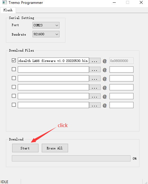
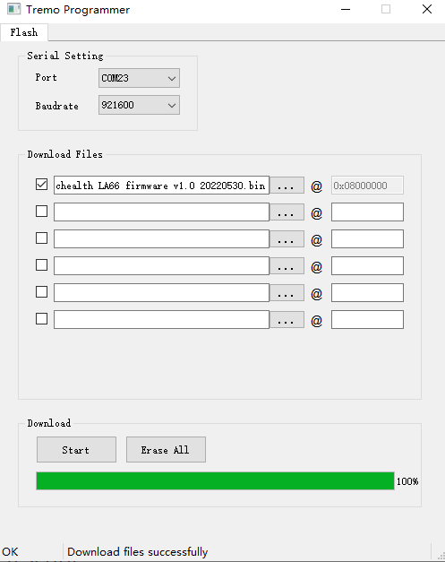
5. Check update process
The following picture shows that the burning is successful
2. FAQ
2.1 How to Compile Source Code for LA66?
Compile and Upload Code to ASR6601 Platform :Instruction
2.2 Where to find Peer-to-Peer firmware of LA66?
Instruction for LA66 Peer to Peer firmware : Instruction
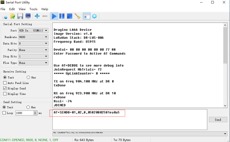
2.3 How to make the device send uplink
Command format:
** AT+SENDB=\<confirn_status\>,\<Fport\>,\<data_len\><data>**
example:
AT+SENDB=01,02,8,05820802581ea0a5
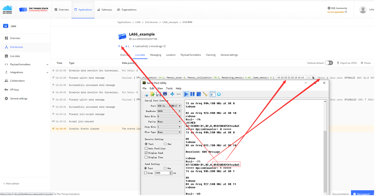
Check to see if TTN received the message
3. Order Info
Part Number: LA66-LoRaWAN-Shield-XXX XXX: The default frequency band
- AS923: LoRaWAN AS923 band
- AU915: LoRaWAN AU915 band
- EU433: LoRaWAN EU433 band
- EU868: LoRaWAN EU868 band
- KR920: LoRaWAN KR920 band
- US915: LoRaWAN US915 band
- IN865: LoRaWAN IN865 band
- CN470: LoRaWAN CN470 band
- PP: Peer to Peer LoRa Protocol
4. Reference
- Hardware Design File for LA66 LoRaWAN Shield : Download
5. FCC Statement
FCC Caution:
Any Changes or modifications not expressly approved by the party responsible for compliance could void the user's authority to operate the equipment.
This device complies with part 15 of the FCC Rules. Operation is subject to the following two conditions: (1) This device may not cause harmful interference, and (2) this device must accept any interference received, including interference that may cause undesired operation.
IMPORTANT NOTE: Note: This equipment has been tested and found to comply with the limits for a Class B digital device, pursuant to part 15 of the FCC Rules. These limits are designed to provide reasonable protection against harmful interference in a residential installation. This equipment generates, uses and can radiate radio frequency energy and, if not installed and used in accordance with the instructions, may cause harmful interference to radio communications. However, there is no guarantee that interference will not occur in a particular installation. If this equipment does cause harmful interference to radio or television reception, which can be determined by turning the equipment off and on, the user is encouraged to try to correct the interference by one or more of the following measures:
—Reorient or relocate the receiving antenna.
—Increase the separation between the equipment and receiver.
—Connect the equipment into an outlet on a circuit different from that to which the receiver is connected.
—Consult the dealer or an experienced radio/TV technician for help.
**FCC Radiation Exposure Statement: **
This equipment complies with FCC radiation exposure limits set forth for an uncontrolled environment.This equipment should be installed and operated with minimum distance 20cm between the radiator& your body.
1
Instruction for LA66 Peer to Peer firmware
1. Overview
This instruction is for how to use Peer to Peer firmware in LA66.
2. Firmware Location and update method
Firmware Location: Click here to download the firmware and update it to LA66 according to the instruction for different boards.
update method: https:///docs/wiki/LoRaWAN-End-Node/lora-modules-accessories/la66-usb-lorawan-adapter/
3. How to use?
3.1 AT command
1). Lora parameter configuration:
AT+FRE Get or Set TX and RX frequency
AT+BW Get or Set TX and RX BandWidth
AT+SF Get or Set TX and RX Spreading Factor
AT+POWER Get or Set Tx Power Range
AT+CRC Get or Set TX and RX CRC Type
AT+HEADER Get or Set TX and RX Header Type
AT+CR Get or Set TX and RX Header Type
AT+IQ Get or Set TX and RX InvertIQ
AT+PREAMBLE Get or Set TX and RX Preamble Length
AT+SYNCWORD Get or Set sync word
2). General configuration:
ATZ Trig a reset of the MCU
AT+FDR Reset Parameters to Factory Default
AT+CFG Print all configurations
AT+FCU Get or Set the Frame Counter Uplink
AT+FCD Get or Set the Frame Counter Downlink
AT+GROUPMOD Get or Set TX and RX group
AT+RXMOD Get or Set Rx Timeout and Reply mode
AT+SEND Send text data or hex along with the application port and confirm status
AT+RECV Print last receive message, RSSI and SNR
3.2 Serial port information
1). Information initialized at reset:

2). In retransmission, the Uplinkcounter does not accumulate. The following figure shows that the third count packet is retransmitted twice when the ACK packet is not received.

3). In the figure below, the receiver sends an ACK to the sender after receiving the packet, and the sender stops retransmission after receiving the ACK. Receiver: (configured as AT+RXMOD=65535,2

Sender:

3.3 Data Format
1 byte of TXGROUPMOD +n payload
Payload(S12, SF11, SF10 maximum length is 59, SF9 maximum length is 123, SF8, SF7 maximum length is 230):
| Size (bytes) | ** 1** | payloadsize |
|---|---|---|
| Value | TXGroupmod | Send data |
4. AT Command Set
4.1 Set TX and RX Bandwidth
Set TX and RX BandWidth (0 ~ 9), AT Command : AT+BW
0: 125 kHz
1: 250 kHz
2: 500 kHz
3: 62.5 kHz
4: 41.67 kHz
5: 31.25 kHz
6: 20.83 kHz
7: 15.63 kHz
8: 10.42 kHz
9: 7.81 kHz
Default Value: AT+BW=0,0 // BandWidth: 125kHz ,125kHz
Range: (0 ~ 9)
4.2 Set TX and RX frequency
Set TX and RX frequency (MHz), AT Command : AT+FRE Default Value: AT+FRE=868.100,868.100 // Frequency: 868.100MHz, 868.100MHz
4.3 Set TX and RX Spreading Factor
Set TX and RX Spreading Factor ( 5 ~ 12), AT Command : AT+SF Default Value: AT+SF=12,12 // Spreading Factor : 12,12
Range: (5 ~ 12)
4.4 Set Tx Power Range
Set Tx Power Range( 0 ~ 22 dBm), AT Command : AT+POWER Default Value: AT+POWER=20 // Output Power: 20dBm
Range: (0 ~ 22)
4.5 Set TX and RX Coding Rate
Set TX and RX Coding Rate ( 1 ~ 4 ), AT Command :AT+CR
1: 4/5
2: 4/6
3: 4/7
4: 4/8
Default Value: AT+CR=1,1 // Coding Rate: 4/5, 4/5
Range: (1 ~ 4)
4.6 Set TX and RX Header Type
Set TX and RX Header Type ( 0,1 ), AT Command : AT+HEADER
0: Variable length packet (explicit header)
1: Fixed length packet (implicit header)
Default Value: AT+HEADER=1,1 // Header Type: explicit, explicit
Range: (0 ~ 1)
4.7 Set TX and RX CRC Type
Set TX and RX CRC Type ( 0,1) ,AT Command:AT+CRC
0: CRC OFF
1: CRC ON
Default Value: AT+CRC=0,0 // CRC: OFF, OFF
Range: (0 ~ 1)
4.8 Set TX and RX InvertIQ
Set TX and RX InvertIQ ( 0,1) , AT Command:AT+IQ
0: Standard IQ setup
1: Inverted IQ setup
Default Value: AT+IQ=0,0 // Invert IQ: 0,0
Range: (0 ~ 1)
4.9 Set TX and RX Preamble Length
Set TX and RX Preamble Length ( 0 ~ 65535 ) , AT Command: AT+PREAMBLE Default Value: AT+PREAMBLE=8,8 // Preamble: 8,8
Range: ( 0 ~ 65535 )
4.10 Set Syncword
Set Syncword(0: private,1: public), AT Command : AT+SYNCWORD Default Value: AT+SYNCWORD=0 // 0x3444 for Public Network
Range: ( 0 ~ 1 )
4.11 Set TX and RX group
Set TX and RX group. (0 ~ 255),AT Command:AT+GROUPMOD
Group > 0: Device only accept same group transmision
Group = 0: Accept Any group
Default Value: AT+GROUPMOD=0,0 // Group: 0,0
Range: ( 0 ~ 255 )
4.12 Set Rx Timeout and Reply mode
**Set Rx Timeout and Reply mode, Parameter 1, Parameter2, AT Command:AT+RXMOD Parameter 1: **
0: Always no RX
1 ~ 65534: Open RX window and last for specify seconds.
65535: RX window always open.
** Parameter 2: **
0: No ACK
1: Send an ACK once got a message from another device. ACK Content is same as receive message
2: Send an ACK once got a message from another device. ACK Content is 0x00 FF
Default Value: AT+RXMOD=65535,2 // RX Mode: 65535, 2
4.13 Send Message
Send Message, AT Command:AT+SEND Parameter 1: send hex or text
0: Send hex
1: Send text
Parameter 2: Content
Parameter 3 : ACK Type
0: No ACK
1: Wait for ACK (Same as what we sent)
2: Wait for ACK ( 0x00 FF)
Parameter 4 : Retransmission ( 0 ~ 8 )
0: No re-transmission
1 ~ 8: total sends 1~8 transmission, interval 5 seconds
Example: AT+SEND=1,hello world,0,3
Notice: RX reply (Defined by AT+RXMOD won't ask for TX ACK
4.14 Print last receive message with RSSI and SNR
Print last receive message with RSSI and SNR,AT+Command:AT+RECV
0: Print in Hex
1: Print in text
Example: AT+RECV=0
The recevied message will be clear after this command.
0