DMT01
1. Introduction
1.1 What is DMT01 Wireless Meat Thermometer
The DMT01 is a professional-grade wireless meat thermometer engineered for accurate, real-time temperature monitoring in commercial cooking environments. Ideal for restaurants, central kitchens, catering services, and food processing facilities, the DMT01 ensures consistent results across various cooking methods—including grilling, smoking, roasting, deep-frying, sous vide, baking, and more. Its precise monitoring helps improve cooking efficiency, ensure food safety, and meet HACCP compliance standards.
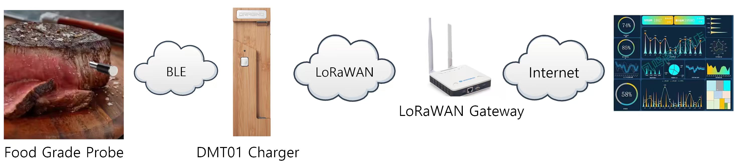
The system consists of two components:
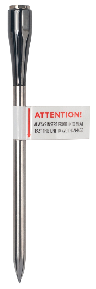
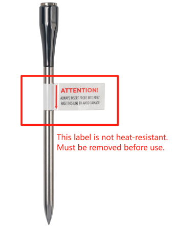
- Food-grade BLE High-Temperature Probe – A durable, high-heat resistant probe that measures internal food temperature during cooking.
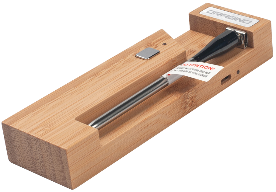
- Charging Base with BLE to LoRAWAN converter – This base not only charges the probe but also acts as a communication bridge. It receives temperature data from the BLE probe and transmits it via the LoRaWAN long-range wireless protocol to your IoT platform or monitoring system.
With its dual wireless support (BLE for close-range/small design and LoRaWAN for long-range data transmission), the DMT01 is ideal for both home cooking enthusiasts and commercial kitchen environments seeking smart, connected temperature monitoring.
1.2 Features
- Wireless Meat Thermometer – Designed for accurate and reliable cooking temperature monitoring
- Food-Grade Probe – Safe for food contact and dishwasher-compatible for easy cleaning
- BLE 5.1 Broadcasting – Supports real-time local data transmission via Bluetooth Low Energy
- LoRaWAN Connectivity – Enables long-range, low-power data transmission to IoT platforms
- Smart Uplink Triggering – Supports periodic data reporting and real-time alerts on temperature thresholds
1.3 Specification
Common DC Characteristics:
- Supply Voltage: +5v via USB Type-C
- Operating Temperature:
Food Probe Spec:
- Length: 126mm
- Diameter: 6mm
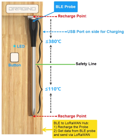
- Food temperature: -30 ~110 °C, Accuracy: ±0.5°C
- Ambient temperature: 0 ~380°C, Accuracy: ±5°C
- Wireless: BLE 5.1
- Distance: ≥ 30m (In an open environment)
- Battery: 4mAh
- Recharge time: < 2 hours
- Battery Duration: >30 hours
- IP Rate: IP67, Dish Washer proof
Charger Spec:
- BLE v5.1 + LoRaWAN
- Power Input: USB Type-C, +5v
- Battery: Li-ion , 3000mAh
- Recharge time: < 2 hours
1.4 Applications
- Commercial Kitchen
- Restaurant
- Catering
- Food Processing
- Central Kitchen
- Cloud Kitchen
- HACCP Monitoring
- Food Safety
- Meat Factory
- Industrial Cooking
1.5 Product Apperance
1.6 Working mode
**Deep Sleep Mode: **Sensor doesn't have any LoRaWAN activate. This mode is used for storage and shipping to save battery life.
Working Mode: In this mode, Sensor will work as LoRaWAN Sensor to Join LoRaWAN network and send out sensor data to server. Between each sampling/tx/rx periodically, sensor will be in IDLE mode), in IDLE mode, sensor has the same power consumption as Deep Sleep mode.
1.7 LED Status
The DMT01 uses a dual-color LED to indicate system status:
| LED Behavior | Description |
|---|---|
| Green breathing effect | Probe is inserted and charging (LED turns off immediately when probe is removed) |
| Red solid (3 seconds) | Mode switched successfully |
| Red blinking (15 seconds) | Charging base low battery (≤20% capacity) |
| Red/Green alternating blink (3 seconds) | Device reset in progress (after 3s long press) |
| Single green blink | BLE connection established between probe and base |
| Single red blink | The charger/repeater box has entered sleep and the probe is removed (blinks once after probe removal) |
| Green light: On for 1.5 seconds and Red light: Flashes once(Execute twice) | The charger/repeater box enters deep sleep |
1.8 Bluetooth Connection Management
This section describes the Bluetooth connection and reconnection behavior between the charging base and the probe.
Reconnection Process:
- When the Bluetooth connection is disconnected, the charging base will automatically initiate a reconnection process.
- The base will make 10 consecutive reconnection attempts, each attempt lasting 30 seconds.
- The total reconnection duration is 300 seconds (5 minutes).
Probe Behavior:
- After disconnection from the charging base, the probe will enter Bluetooth broadcast mode.
- In this mode, the probe can be discovered by other Bluetooth devices.
- The probe's Bluetooth broadcast name is: K10-BTS-P
Connection Recovery:
- If the probe returns within effective Bluetooth communication range within 5 minutes, the connection will be automatically restored. (Note: The actual effective range may vary depending on the usage environment)
- If the probe remains out of effective communication range for more than 5 minutes, it will maintain broadcast mode.
- To manually re-establish the connection: return the probe to the charging base and then remove it.

1.9 Button Function
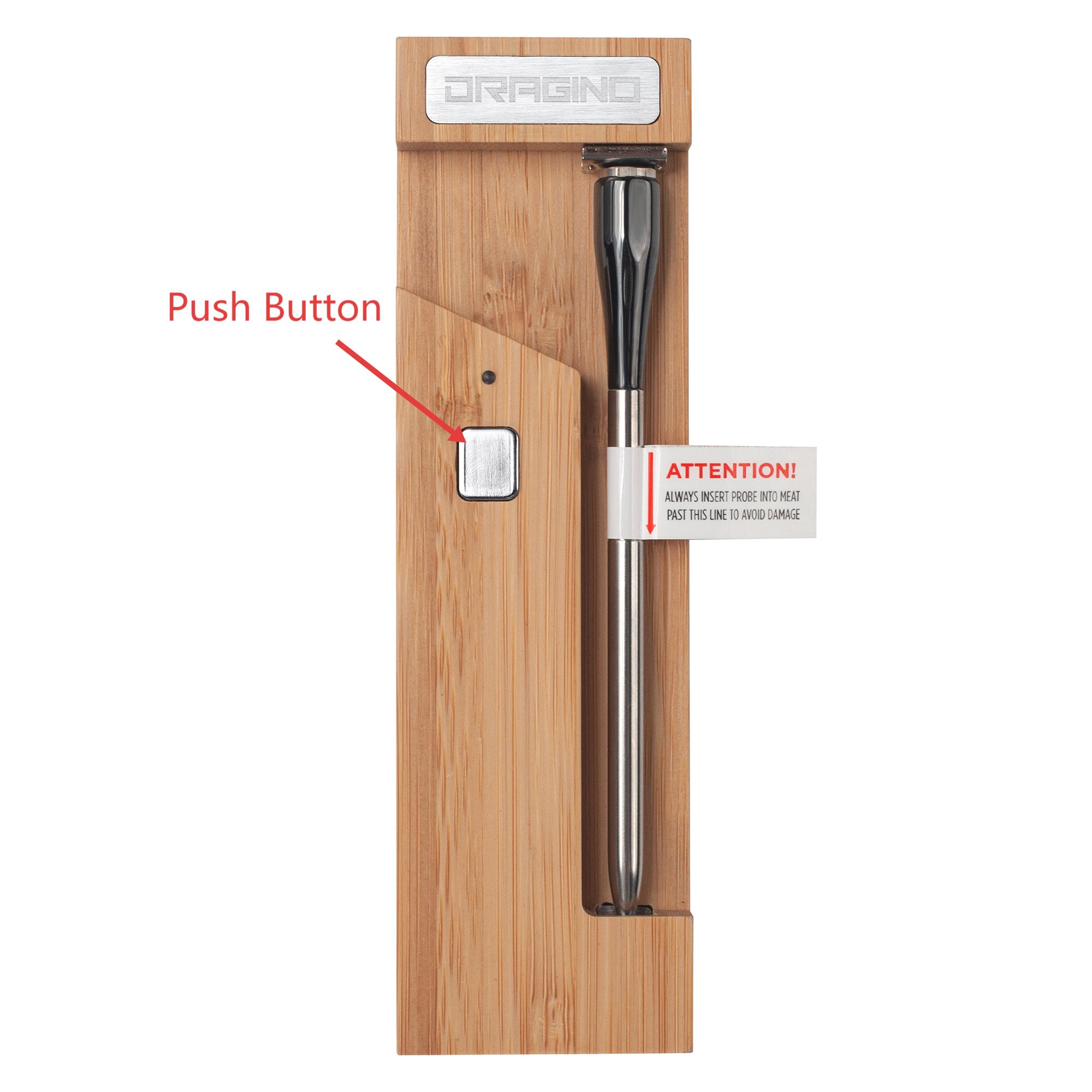
| Behavior on ACT | Function | Action |
|---|---|---|
| Active Device | **Red **and **Green **LEDs blink alternately for 3 seconds. DMT01 will enter working mode and start joining the LoRaWAN network. Please remove the probe before performing the activation operation. When the probe is placed in the repeater for charging, the green LED on the charger/repeater box will display a breathing effect. The LED turns off when the probe is removed. Note: Each time the device is activated, the DMT01 will automatically switch to the default BLE/LoRa mode. | |
| Entering a deep sleep state | When the device successfully enters the low power state, the LED light will flash green and red. When the light goes out, it successfully enters the low power state. When you need to wake up the device, you need to reset the device. Note: The probe needs to be safely placed in the relay box. |
Note: When the device is in deep sleep state and needs to be started, you need to take out the probe first, and then press and hold the ACT button on the charger/repeater box for 3 seconds. The charger/repeater box will reset the LoRa module and re-apply to join the LoRa network.
1.10 Power on device and Recharge Probe
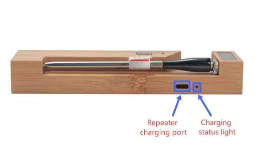
- When the repeater is charging, the charging indicator light will be solid red.
- When the repeater is fully charged, the charging indicator will be solid green.
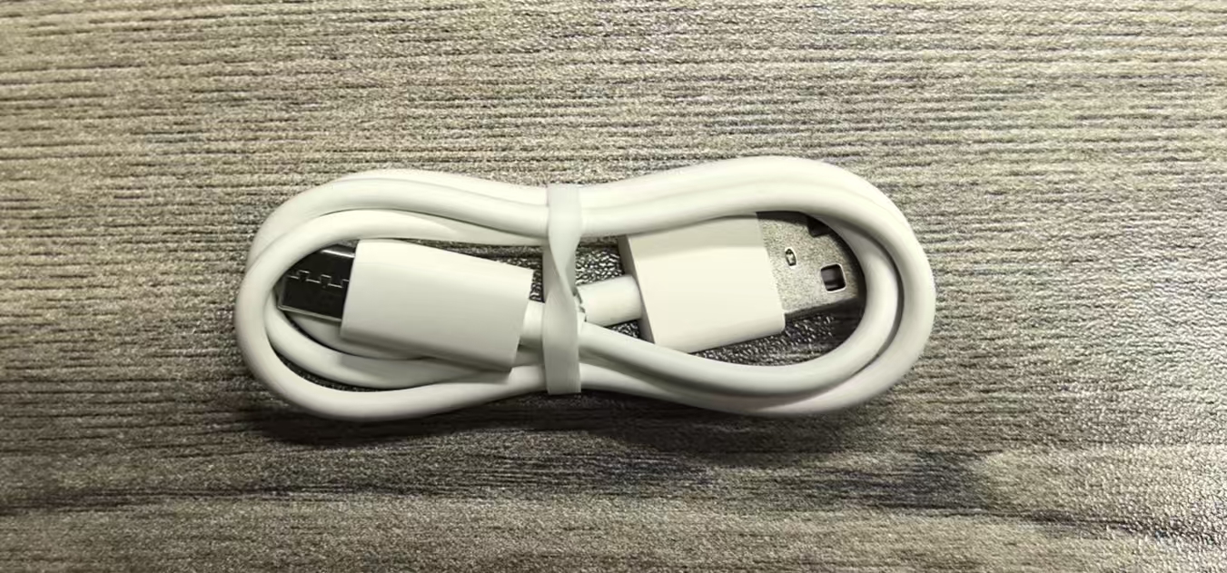
Warning: Use Only Supplied Cable
For optimal performance, please use the dedicated white USB cable provided to charge your DMT01 Repeater. This cable is designed with a specific charging protocol to ensure compatibility and safe charging. The use of third-party cables is not recommended and may prevent the device from charging properly.
Note: Due to uncertain transit and storage duration, your DMT01 may arrive with a depleted battery. It is recommended to charge the device immediately upon receipt using the dedicated white USB cable provided. If the LED on the front of the repeater does not show a green breathing light effect during charging, try removing the probe and reinserting it into the repeater.
2. Use DMT01
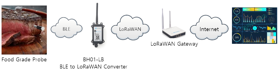
2.1 How it works
DMT01 include two parts,
- The food grade probe: Used to measure the temperature inside meat.
- The Charger with an integrated LoRaWAN End device: Connects the probe via BLE, retrieves the temperature, and sends it via LoRaWAN to the network server.
Consider the BLE coverage. There are two modes:
Connection Mode: The probe is nearby the charger/repeater box, within BLE range.
The probe will establish a connection to the charger/repeater box via BLE, and the data flow is as shown below.

Broadcast Mode: The probe is far away from the charger, outside the BLE range.
The probe will automatically switch to BLE broadcast mode and transmit the data via BLE. Any BLE scanner can pick up the signal and send it to the IoT server.
For example:
1) The user can use the BH01 BLE-to-LoRaWAN converter to pick up the BLE signal and forward it to the IoT server.
2) The user can use a mobile phone to receive the broadcast signal and process it further.
2.2 Activate Device
To activate the DMT01:
- Use the provided registration information (DevEUI, AppEUI, AppKey) to register the device with the LoRaWAN Network Server to enable OTAA (Over-the-Air Activation).
- Make sure there is LoRaWAN network coverage in your area that supports the network server you have chosen. If not, you can use a LoRaWAN gateway to extend the network coverage
- Press the button on the DMT01 for more than 3 seconds. The DMT01 will start connecting to the LoRaWAN network.
- After the DMT01 joins the LoRaWAN network, remove it (the probe) from the charger/repeater. The probe will start measuring temperature, and you will be able to see the data on the server.
2.3 Quick guide to connect to a LoRaWAN server (OTAA)
In this example, we use The Things Stack as the LoRaWAN network server to show you how to register the DMT01 with a LoRaWAN network server and how to activate it using OTAA. In this network diagram, the probe sends data packets to the charger/repeater unit via BLE. The repeater then converts those BLE data packets to LoRa packets and sends them to the Network Server.
In this example, we use the LPS8v2 as the LoRaWAN gateway.
Step 1: Create a device in The Things Stack with the OTAA registration information (keys) from DMT01.
Each DMT01 is shipped with a unique DevEUI, AppEUI, and AppKey. You can find it inside the package of the device. Please keep your registration information in a safe place and don't share with anyone.

You can enter this key in the LoRaWAN Network Server portal.
The following steps describe how to do it with The Things Stack network server portal. Follow the screenshots for correct configuration:
Create the application.
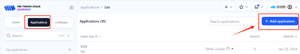
- On the home screen, click the + Add application button.
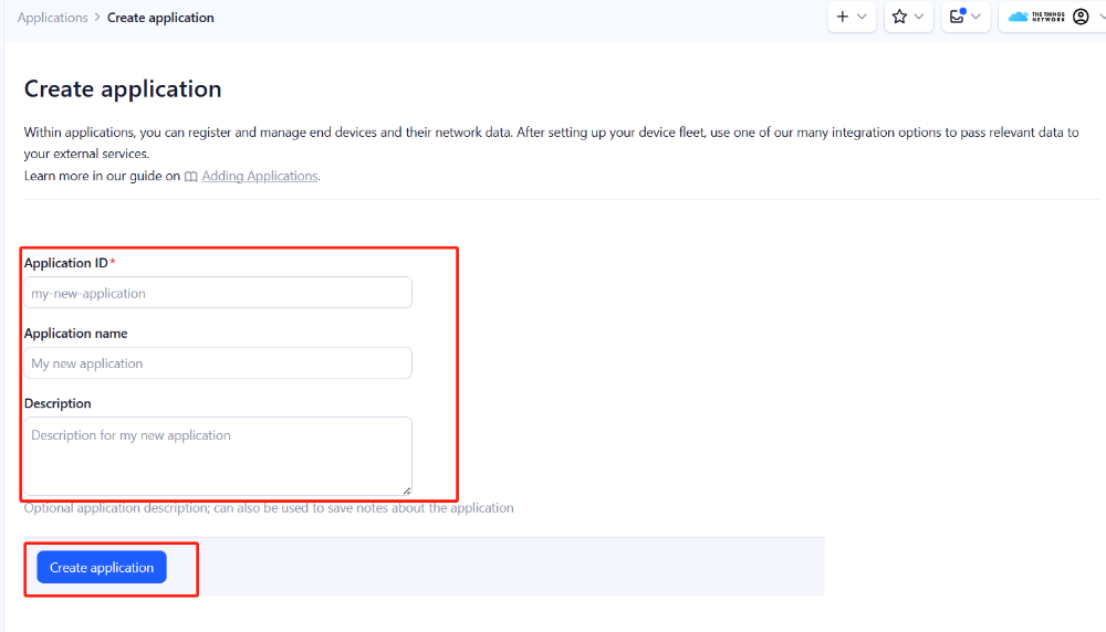
- On the Create application page, enter an Application ID to identify your **application **within The Things Stack and provide an Application name. Read https://thethingsindustries.com/docs/integrations/adding-applications for more information on how to do that.
- Click the Create application button.
Add devices to the created Application
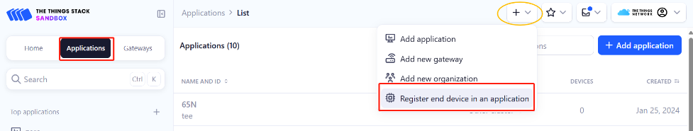
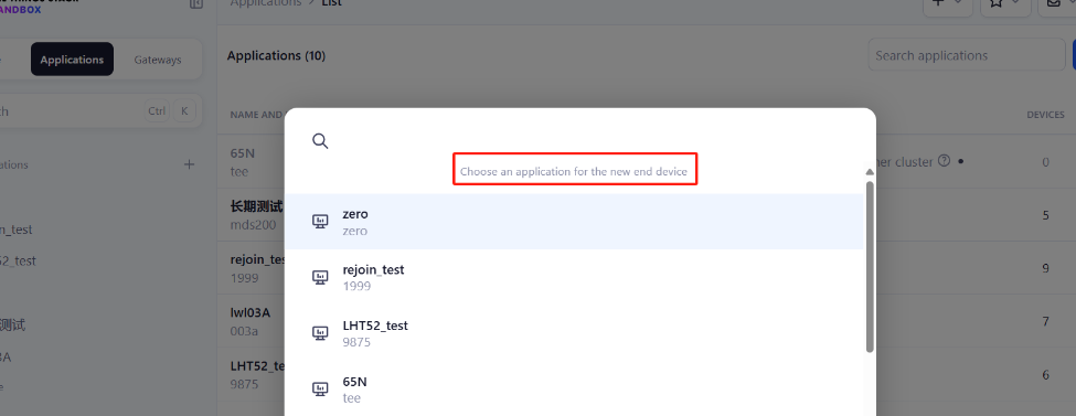
- After creating the application, you will be redirected to the Application overview page.
- On the Application overview page, click the + Register end device button.
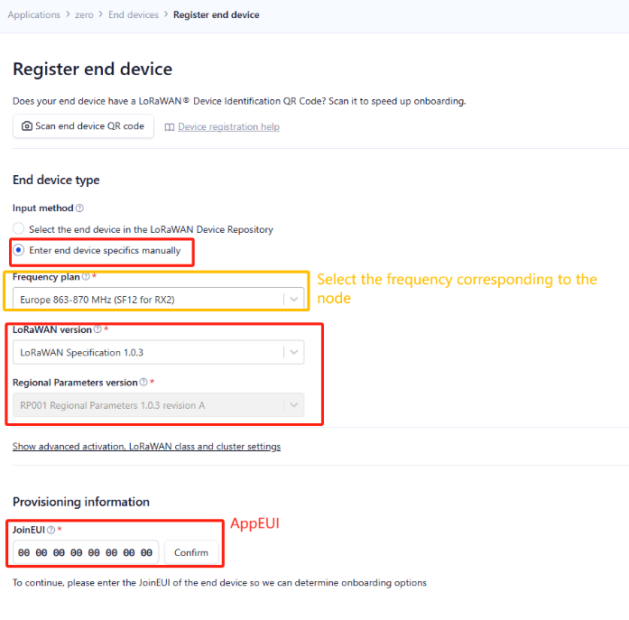
Enter end device specifics manually
We use Over The Air Activation (**OTAA) **to activate DMT01 with The Things Stack. OTAA is the most secure way of activating an end device with a LoRaWAN network server.
- On the Register end device page, select the ‘Enter end device specifics manually’ option under the input method.
- Select the correct Frequency plan and LoRaWAN version. The Regional parameters version will appear automatically based on the LoRaWAN version
The Frequency plan should match the frequency of the DMT01.
Using the registration information sheet that comes with the DMT01,
- Fill the JoinEUI. The DMT01 uses **AppEUI **instead of JoinEUI. You can enter it in the JoinEUI text box. Then click the **Confirm **button.
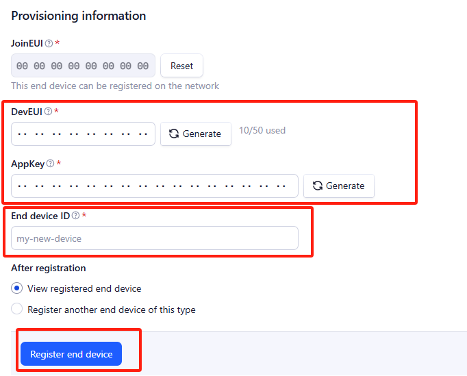
Add DevEUI and AppKey
- Enter the **DevEUI **and AppKey.
- Enter an End device ID that can be used to identify your DMT01 within this application.
Click the Register end device button.
**Step 2: **Add decoder
LoRaWAN uplink and downlink payloads are encoded. To understand the data, you need a small script to decode them. We use a JavaScript function for this. It is called a payload formatter. It reads the payload and extracts useful information, such as relay status, event type, and timestamp. We have written a JavaScript function to decode uplinks from the DMT01 device.
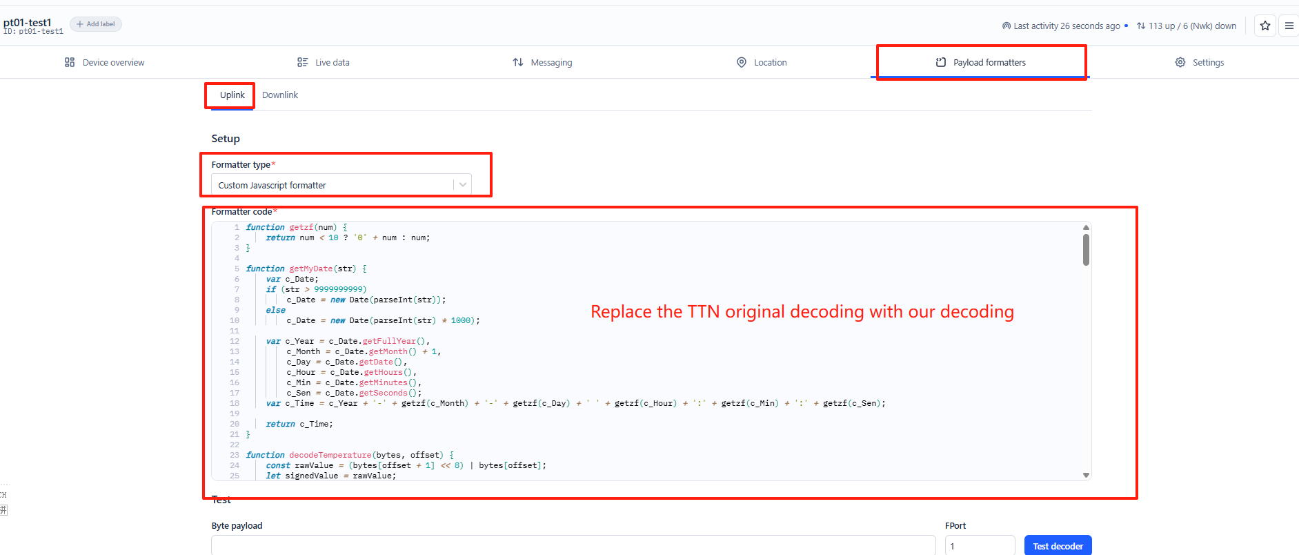
To add an uplink payload formatter code to The Things Stack, follow the steps below:
- Go to your DMT01 device page and click Payload formatters.
- Click, Uplink.
- Select Custom Javascript formatter from the **Formatter type **drop-down list.
- Now copy the Uplink Formatter code from here: https://github.com/dragino/dragino-end-node-decoder/tree/main/
- Then paste it in the **Formatter code **box:
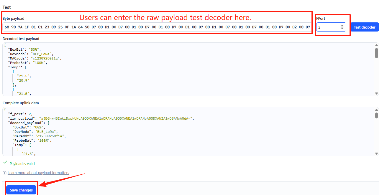
You can now test the formatter code with a sample payload.
- Enter 68 90 7A 1F 01 C1 23 09 25 0F 1A 64 50 D7 00 D1 00 D7 D1 00 D7 00 D1 00 in the Byte payload box.
- Change the **FPort **to 2 (because our payload formatter only accepts uplinks from FPort 2).
- Click the Test decoder button.
The payload will be decoded into the following JSON object and shown in the Decoded test payload box.
To save the payload formatter, click the Save changes button.
After applying the uplink payload formatter, you can see that all uplink payloads shown in the Live Data section are decoded into fields.
Step 3: Activate the DMT01
Press the **ACT **button for 3 seconds to activate the DMT01. After a successful join, it will start uploading messages to The Things Stack, and you can see them in the Live data panel.
2.3 LoRaWAN Payload
DMT01 uses different types of LoRaWAN payload formats.
2.3.1 Probe In-Place Detection and Status Reporting, FPort=6
This port is used for reporting probe placement status, charging events, and periodic keep-alive messages.
There are three primary triggering scenarios:
- When the probe is inserted into or removed from the charger/repeater box, an event packet is sent uplink.
- When the probe has reached full charge while placed in the charger/repeater box, a charging completion event packet is sent uplink.
- When the probe remains inserted in the charger/repeater box (without the box being manually put into deep sleep), a keep-alive status packet is automatically sent every 2 hours.
The payload includes the Timestamp, ProbeEvent, and the battery level of the charger/repeater box. The format is as follows:
| Device Status (FPort=6) | ||||
| Size (bytes) | 4 | 1 | 1 | |
| Value | Timestamp | ProbeEvent | charger/repeater box battery level (BoxBat) |
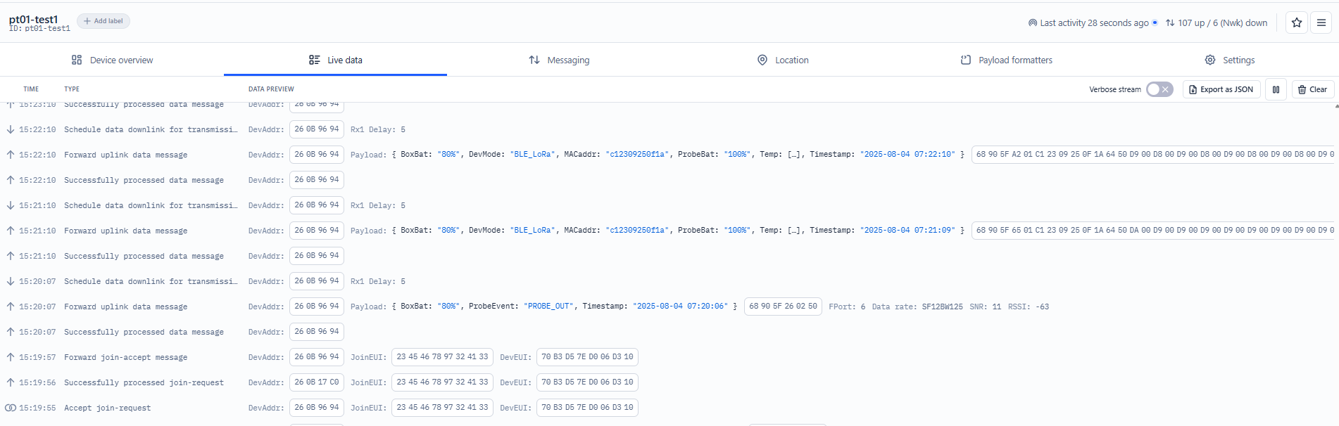
Example in The Things Stack:
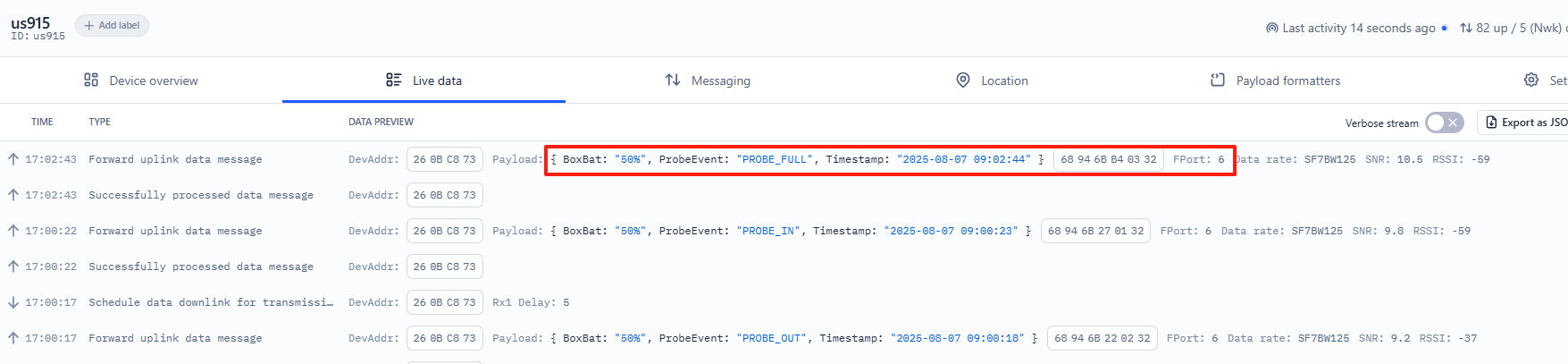
Timestamp: 0x68946BB4
ProbeEvent:
0x04 = KEEP_ALIVCE (indicates that the charger/repeater box is online)
**0x03 **= PROBE_FULL (indicates that the probe is fully charged)
**0x02 **= PROBE_OUT (indicates that the probe is taken out of the charger/repeater box)
**0x01 **= PROBE_IN (indicates that the probe is placed in the charger/repeater box)
BoxBat: 0x32 = 50%
2.3.1 Device Status, FPort=5
You can use the downlink command (0x26 01) to request DMT01 to send its configuration details, including the device configuration status. DMT01 will uplink a payload to the LoRaWAN Network Server via FPort = 5.
The Payload format is as below.
| Device Status (FPort=5) | |||||
| Size (bytes) | 1 | 2 | 1 | 1 | |
| Value | Sensor Model | Firmware Version | Frequency Band | Sub-band |
Example in The Things Stack:
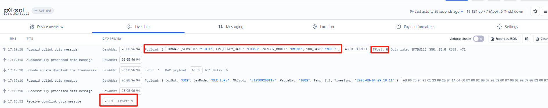
Sensor Model: For DMT01, this value is 0x4B
Firmware Version: 0x0101, which means v1.0.1
Frequency Band:
0x01: EU868
0x02: US915
0x03: IN865
0x04: AU915
0x05: KZ865
0x06: RU864
0x07: AS923
0x08: AS923-1
0x09: AS923-2
0x0a: AS923-3
0x0b: CN470
0x0c: EU433
0x0d: KR920
0x0e: MA869
Sub-Band:
AU915 and US915: value 0x00 ~ 0x08
CN470: value 0x0B ~ 0x0C
Other Bands: Always 0x00
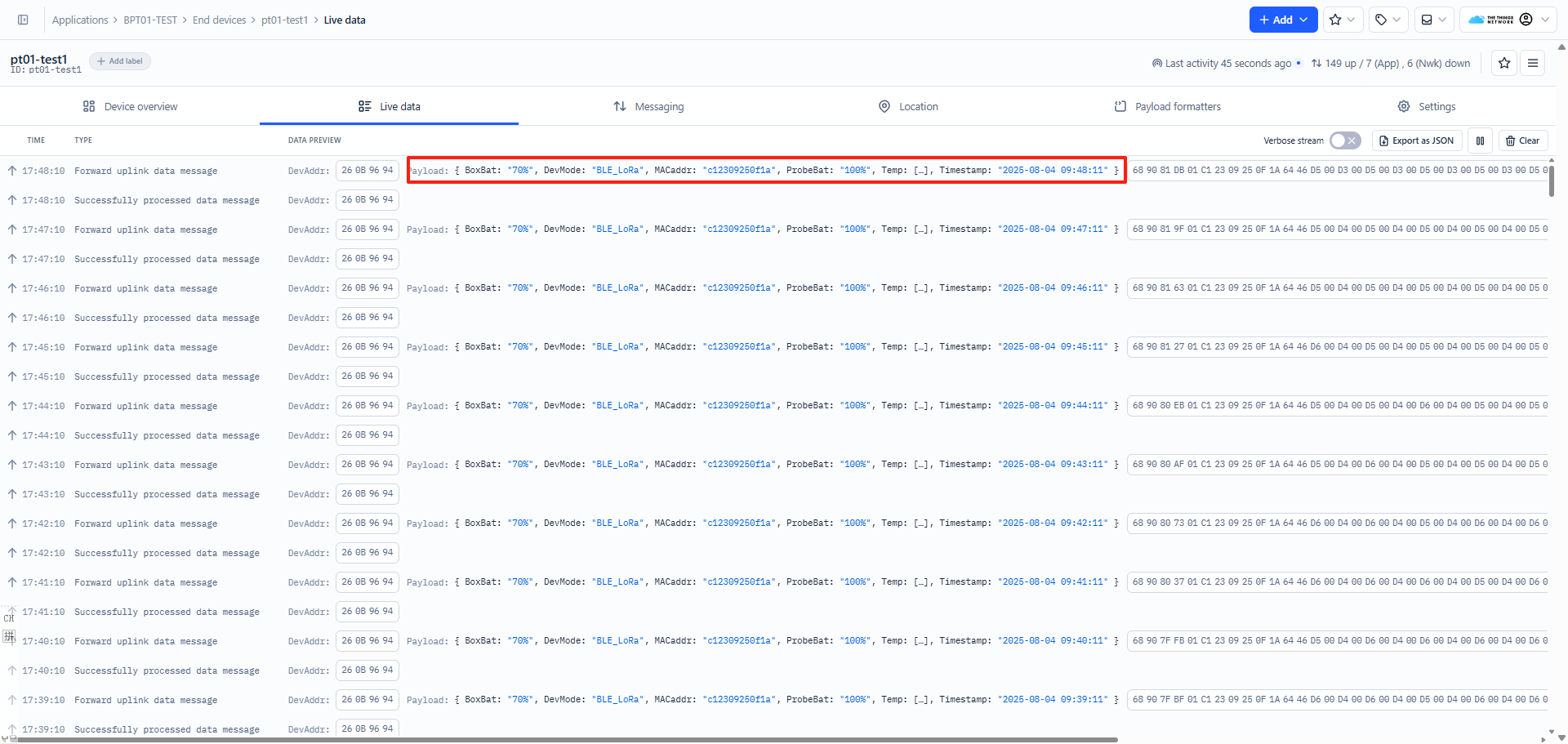
2.3.2 Sensor Data, FPort=2
This port is used for uplinking sensor data readings. After the DMT01 is connected to the LoRaWAN network and is in normal operation mode, once the probe is removed from the charger/repeater box, a BLE connection is established between the probe and the box. The charger/repeater box will then uplink sensor data packets periodically via FPort=2.
The uplink interval is determined by the probe sampling interval multiplied by the number of samples, as configured in the Multi-Sampling command. By default, the sampling interval is 6 seconds with 10 sample groups, resulting in an uplink every 60 seconds. Therefore, the charger/repeater box transmits this data packet every 1 minute by default.
The Payload format is as below.
| Size(bytes) | 4 | 1 | 6 | 1 | 1 | 2 | 2 |
|---|---|---|---|---|---|---|---|
| Value | Timestamp | DevMode | MACaddr | ProbeBat | BoxBat | Food temperature | Ambient temperature |
Unix Timestamp
UNIX Timestamp Example: 689085D7(H) = 1754301911(D)
Convert the decimal value using (https://www.epochconverter.com)) to get the corresponding time.
DevMode
Example:
If the payload is 0x01: BLE_LoRa
If the payload is 0x02: LoRa
If the payload is 0x03: BLE
MACaddr
Example:
If the payload is C12309250F1A, the MACaddr is C12309250F1A
ProbeBat
Example:
If the payload is 0x64 = 100%
BoxBat
Example:
If the payload is 0x46 = 70%
Food temperature
Because the food temperature data is in little-endian format, the order of the bytes needs to be swapped during decoding.
Example:
If the payload is: D300 = 00D3(H) , (00D3 & 8000 == 0), the **temp **=00D3H/10 = 211 /10 = 21.1 ℃
If the payload is: 7D80 = 807D(H), (807D & 8000 == 1), the **temp **= -(807D & 7FFF)/10 = -125/10=-12.5 ℃.
Ambient temperature
Because the food temperature data is in little-endian format, the order of the bytes needs to be swapped during decoding.
Example:
If the payload is: D300 = 00D3(H) , (00D3 & 8000 == 0), the **temp **=00D3H/10 = 211 /10 = 21.1 ℃
2.4 Bluetooth Broadcast Payload
2.4.1 Relay Box Broadcast Payload
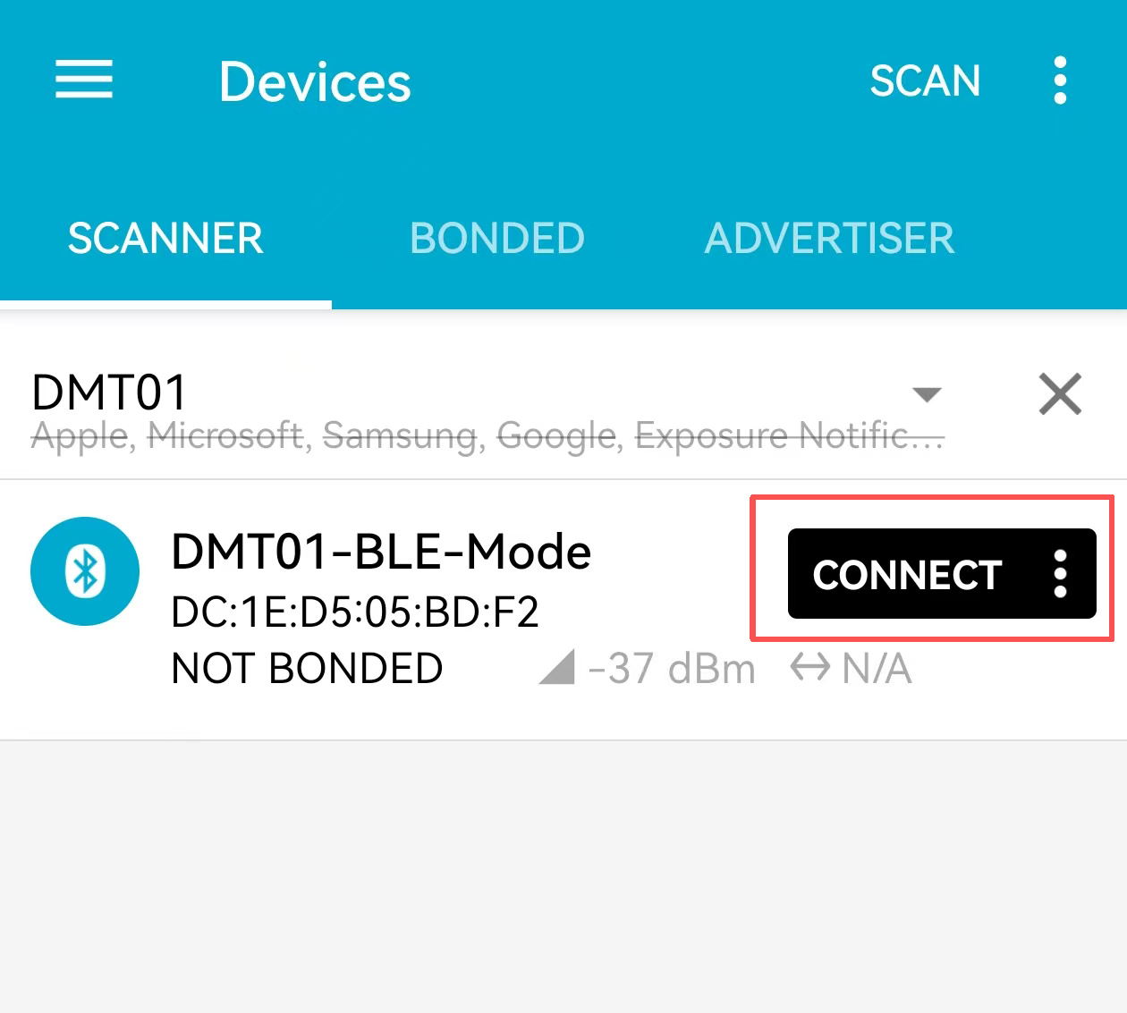
When the relay box is connected to the probe via Bluetooth, it periodically broadcasts its own status and measurement data of probe. Use a third-party mobile app (such as nRF Connect) to scan and obtain the broadcast data from the relay box.
Operation Steps:
1. Open the nRF Connect application
2. Start scanning for Bluetooth devices
3. Look for the device named in the scan results
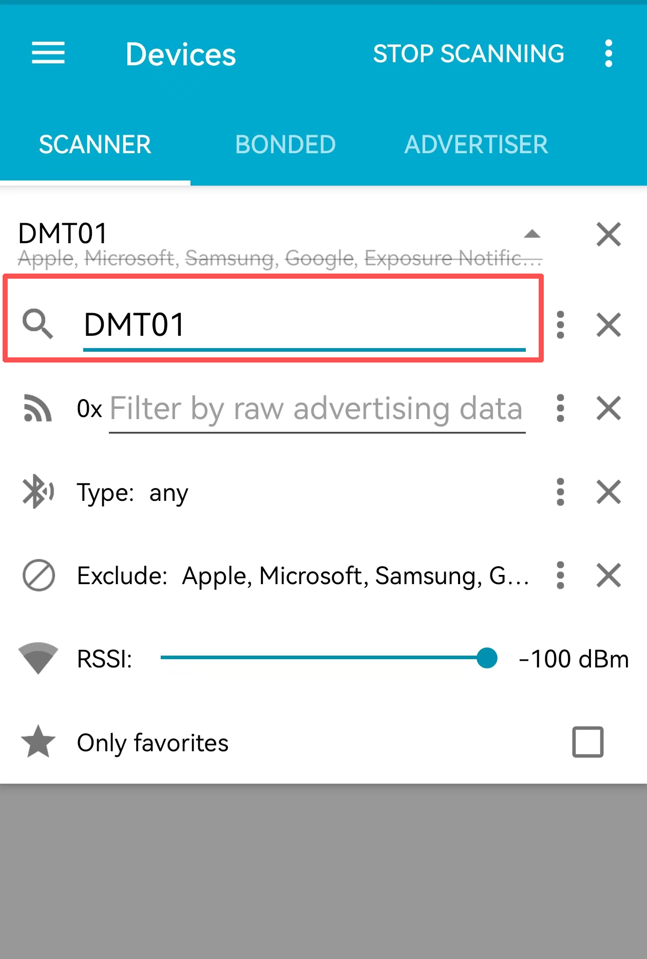
4. Click on the DMT01 device to establish a connection
5. Once connected, view and capture the raw broadcast data
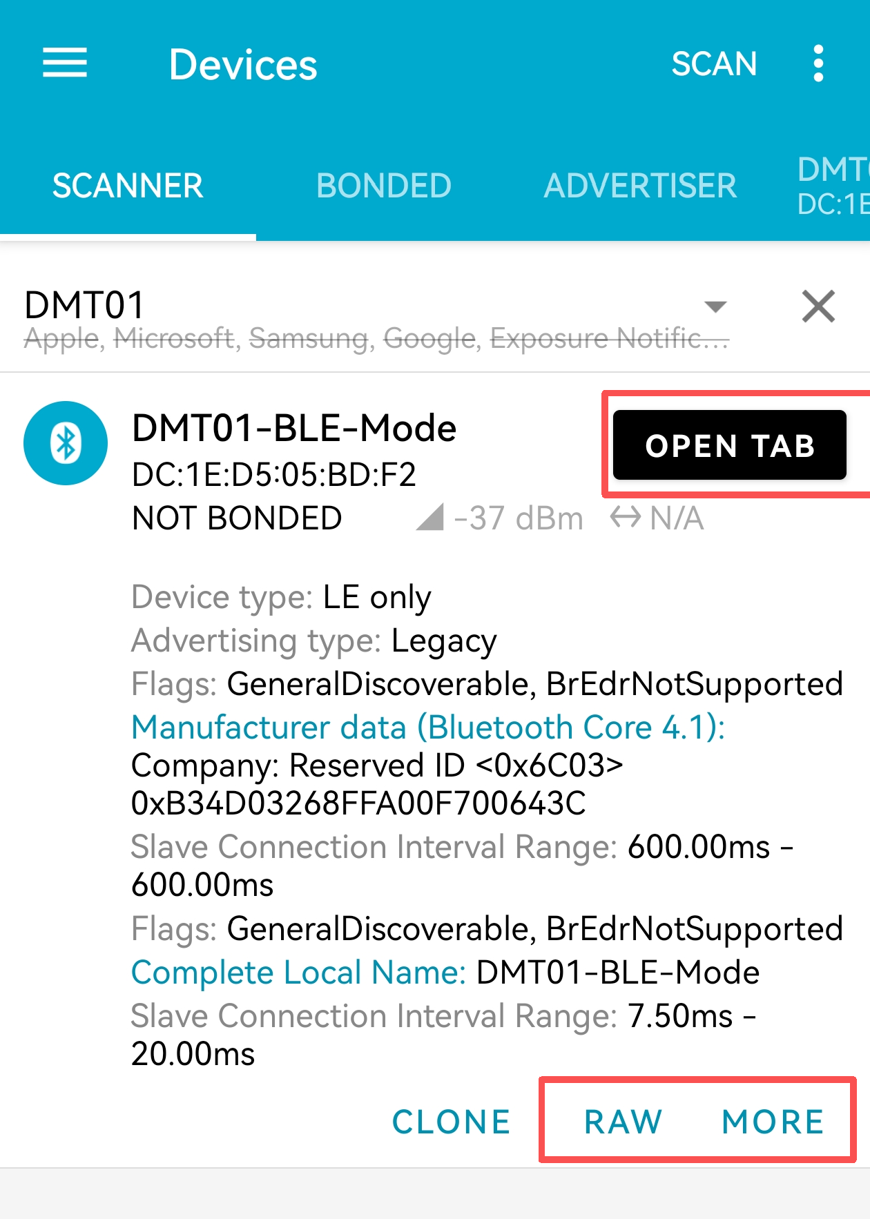
Example:
The following broadcast payload was captured using nRF Connect for Mobile app when connected to a DMT01 relay box:
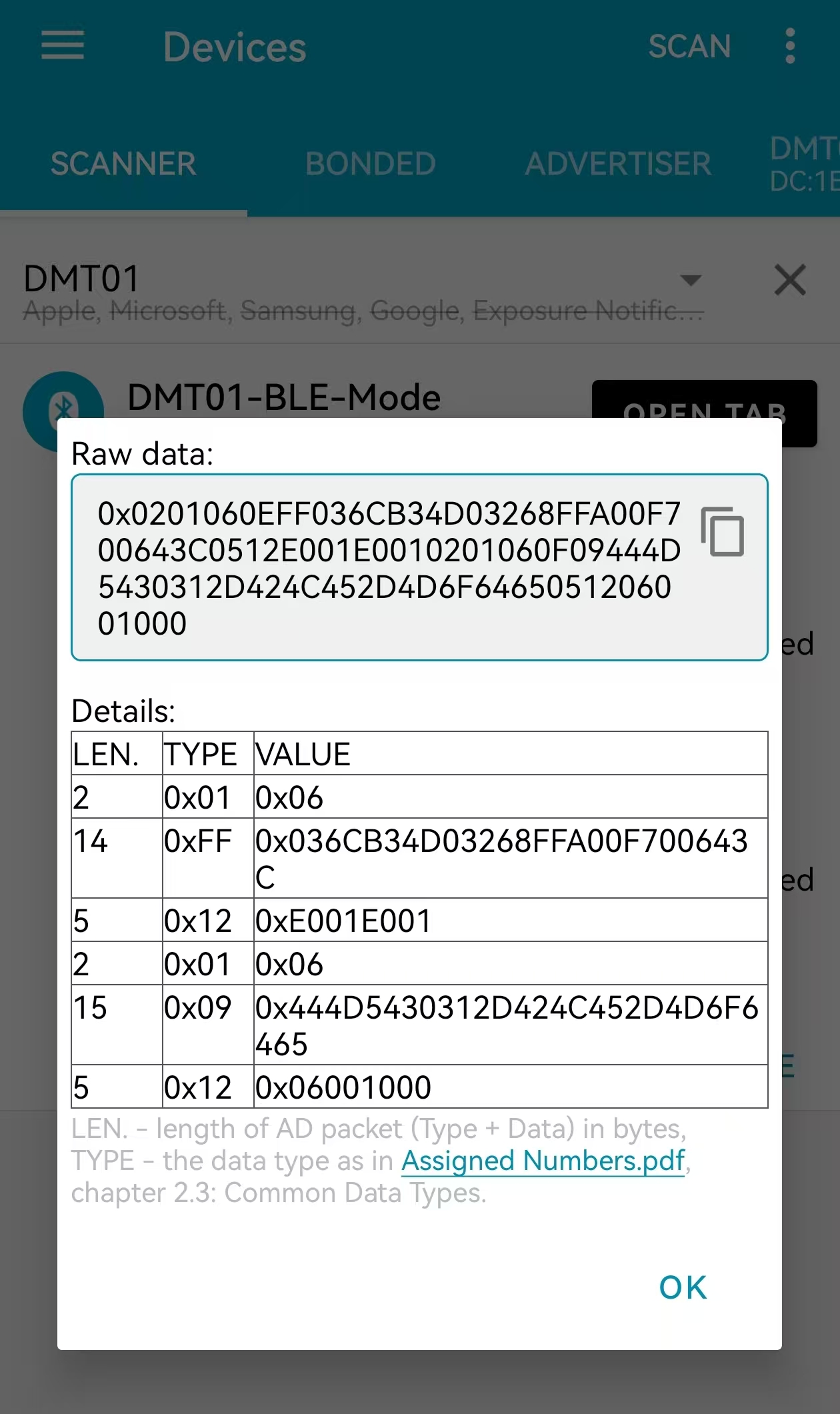
If the scanned payload is 0x0201060609444D5430310EFF **01C12309250F1AD100CD006446 **0512E001E001
**Note: **
- The first 12 bytes in the payload are the Bluetooth packet header data and do not need to be decoded.
- The last 6 bytes in the payload are the Bluetooth packet trailer data and do not need to be decoded.
So the payload is:01C12309250F1AD100CD006446
- Bluetooth data packet frame header
Example: 0x0201060609444D5430310EFF
- DevMode
Example:
![]()
If the payload is 0x01: BLE_LoRa
If the payload is 0x02: LoRa
If the payload is 0x03: BLE
- MACaddr
Example:
![]()
If the payload is C12309250F1A, the MACaddr is C12309250F1A
- ProbeBat
Example:
![]()
If the payload is 0x64 = 100%
- BoxBat
Example:
![]()
If the payload is 0x46 = 70%
- Food temperature
Because the food temperature data is in little-endian format, the order of the bytes needs to be swapped during decoding.
Example:
![]()
If the payload is: D100 = 0x00D1(H), (00D1 & 8000 == 0), the temp = 00D1H/10 = 209/10 = 20.9 ℃
If the payload is: BD80 = 80BD(H), (80BD & 8000 == 1), the **temp **= -(80BD & 7FFF)/10 = -189/10=-18.9 ℃.
- Ambient temperature
Because the food temperature data is in little-endian format, the order of the bytes needs to be swapped during decoding.
Example:
![]()
If the payload is: CD00 = 0x00CD(H), (00CD & 8000 == 0), the temp = 00CDH/10 = 205/10 = 20.5 ℃
- Bluetooth data packet frame tail
Example: 0x0512E001E001
2.4.2 Probe Broadcast Payload
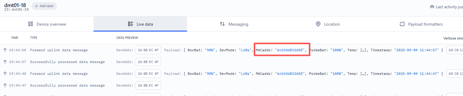
When the Bluetooth connection between the relay box and the probe is disconnected, the probe will automatically enter independent broadcast mode. In this state, the probe can be directly scanned and accessed using a mobile application such as nRF Connect. The probe broadcasts under the name K10-BTS-P, and can also be identified by its unique MAC address (e.g., 6C:B3:4D:03:26:8F). Example:
Operation Steps:
1. Disconnect the Bluetooth connection between the relay box and the probe: The distance between the relay box and the probe exceeds the effective Bluetooth range, causing an automatic disconnection.
2. Open the nRF Connect application on your mobile device.
3. Start scanning for nearby Bluetooth devices.
4. Look for the device named K10-BTS-P in the scan results.
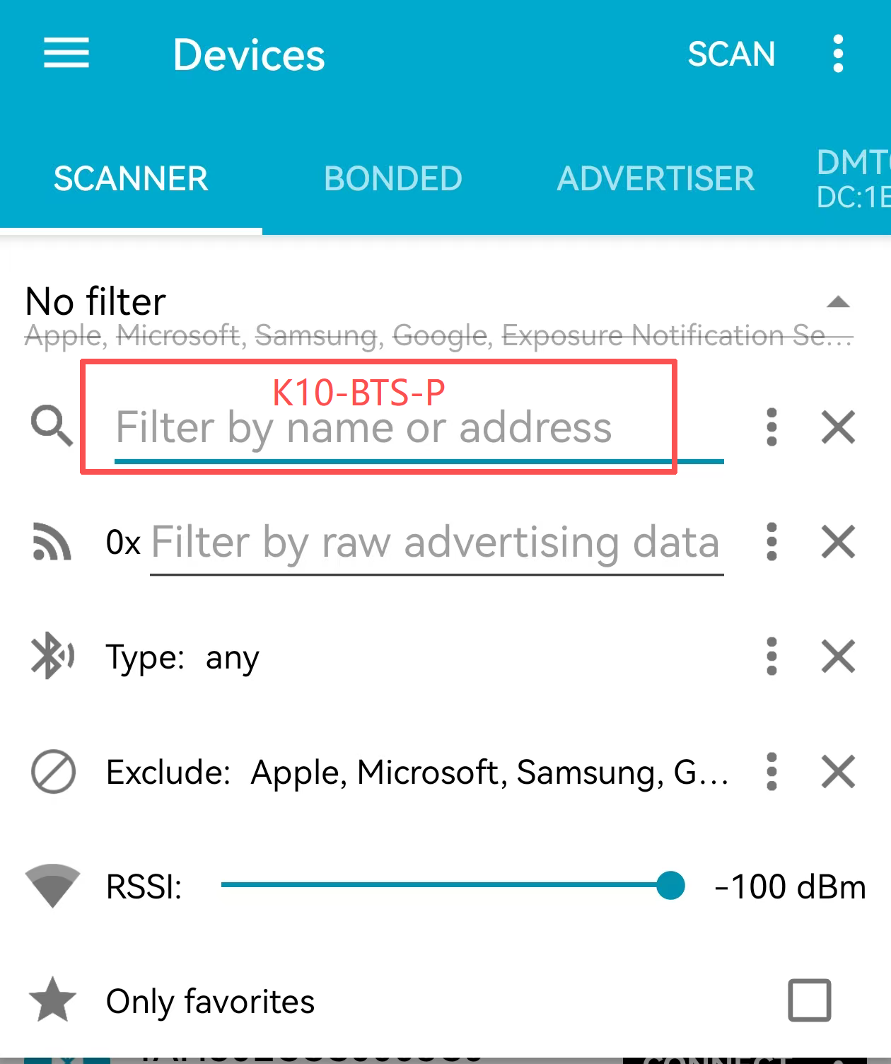
5. Select the target probe to connect.
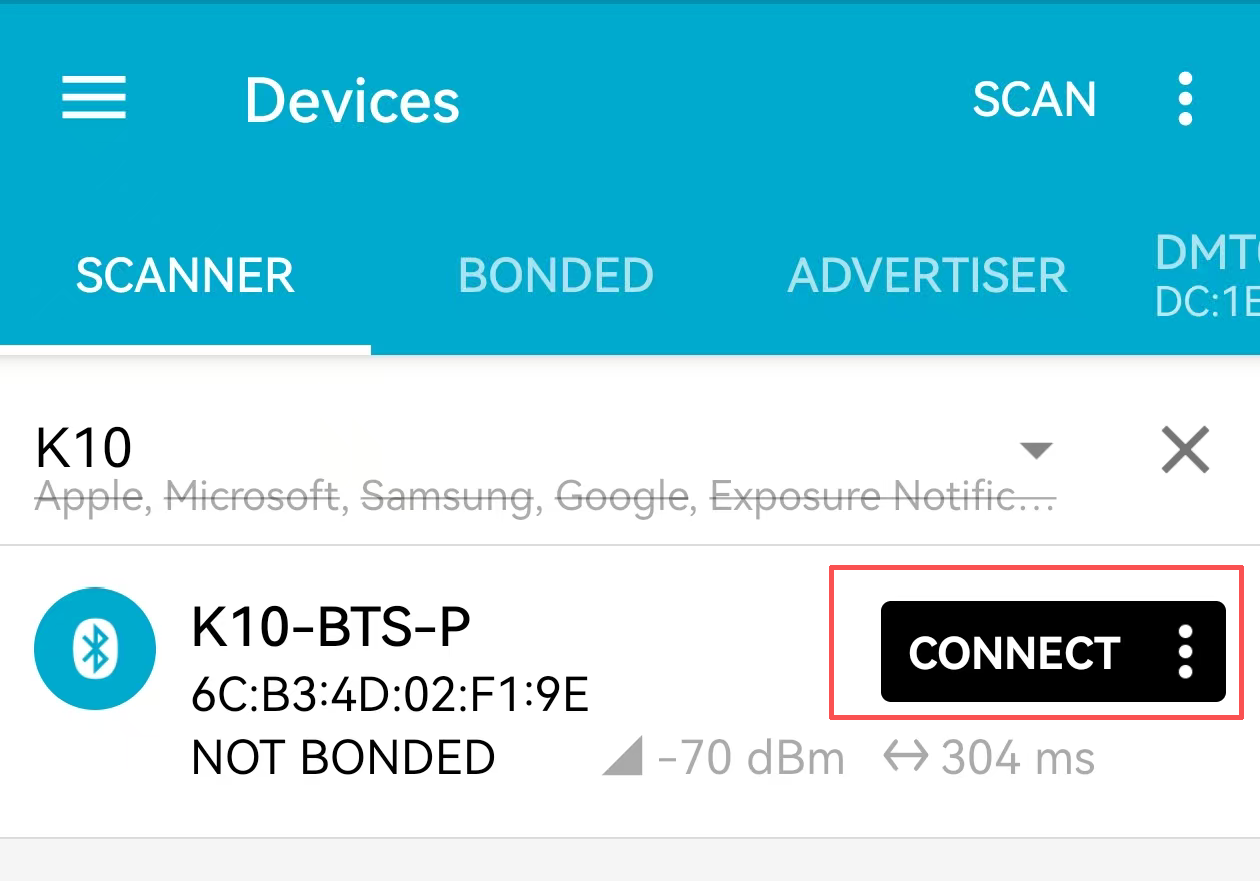
6. View and capture the raw broadcast data transmitted by the probe.
Example:
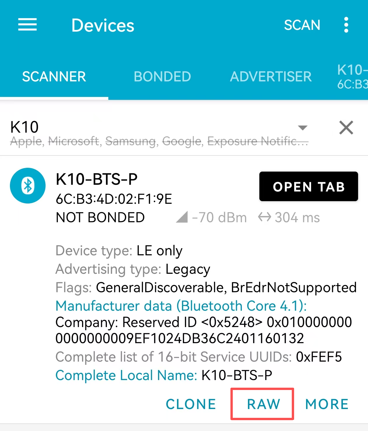
A typical broadcast payload from the probe may appear as follows:
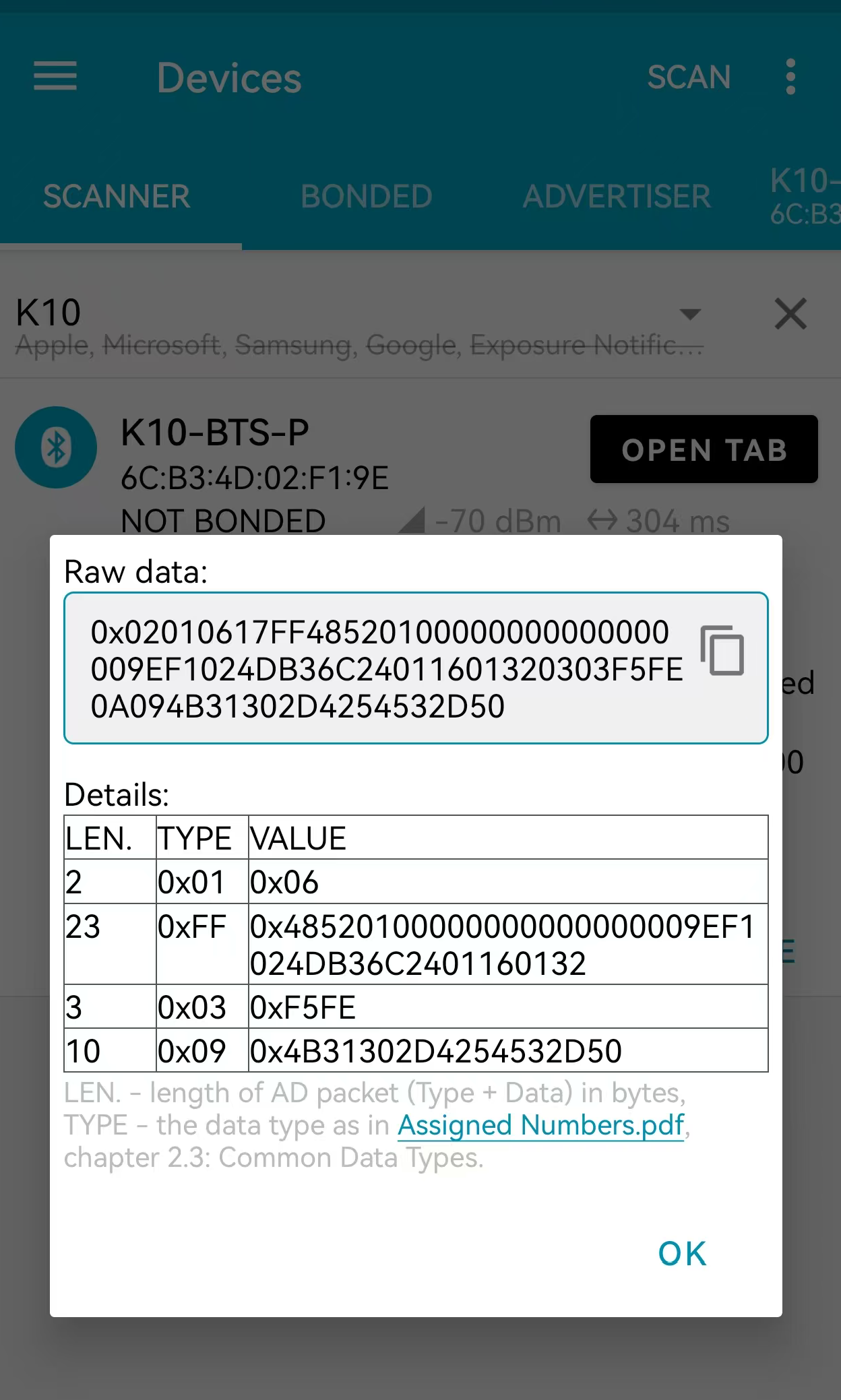
The raw data from the probe includes broadcast data and scan response data, which are parsed as follows:
**broadcast data: **
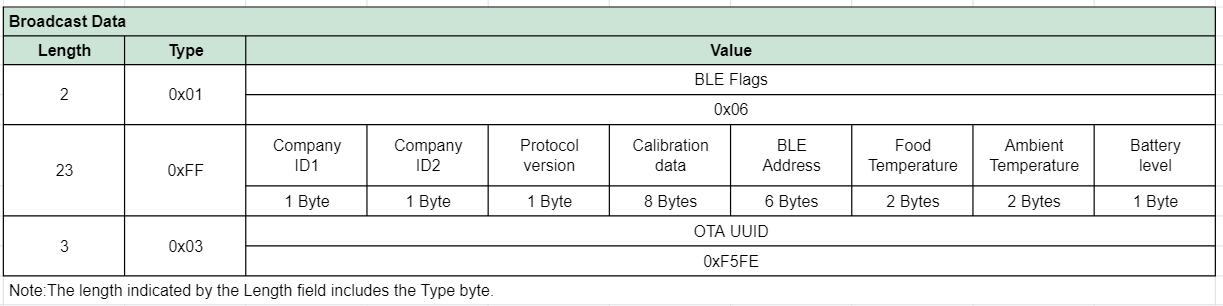
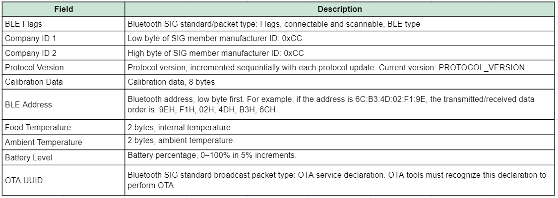
**Field Descriptions: **
scan response data:
The scan response packet contains the Bluetooth name, formatted as follows:

If the scanned payload is 0x020106 17FF4852010000000000000000 9EF1024DB36C 2401 1601 32 0303F5FE 0A094B31302D4254532D50
- BLE Flags
Example:
![]()
If the payload is 0x02: Indicates a byte length of 2 bytes.
![]()
If the payload is 0x01: Indicates data type 1.
![]()
If the payload is 0x06: Indicates Bluetooth flag bit 06.
- BLE address
Example:
![]()
The BLE address is 6C:B3:4D:02:F1:9E
Food temperature
Ex1:
If the payload is: ![]()
Because the food temperature data is in little-endian format, the order of the bytes needs to be swapped during decoding.
If the payload is 2401 = 0x0124(H), (0124 & 8000 == 0), the temp = 0124H/10 = 292/10 = 29.2 ℃
Ex2:
If the payload is: BD80 = 80BD(H), (80BD & 8000 == 1), the **temp **= -(80BD & 7FFF)/10 = -189/10=-18.9 ℃.
- Ambient temperature
Ex1:
If the payload is: ![]()
Because the Ambient temperature data is in little-endian format, the order of the bytes needs to be swapped during decoding.
If the payload is 1601 = 0x0116(H), (0116 & 8000 == 0), the temp = 0016H/10 = 278/10 = 27.8 ℃
- Battery level
![]()
If the payload is 0x32 : 0x32(H)=50(D), Indicates Battery level is 50%.
2.5 Use the BH01-LB to capture the Bluetooth Payload
When the meat probe is out of the DMT01 Bluetooth range, it will automatically switch to BLE broadcast mode, and the sensor data can be captured by the BH01-LB via BLE and sent to the LoRaWAN Network Server.
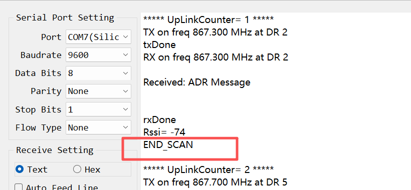
2.5.1 BH01-LB Scanning Operation
By default, the BH01-LB/LS device supports scanning for DMT01 probes and uploading data via LoRaWAN.
The BH01-LB/LS device can scan multiple probes simultaneously and upload their data at the same time. Uploaded data can be viewed on a LoRaWAN platform (e.g., The Things Stack).
You can modify the scanning mechanism of the BH01-LB/LS to disable scanning for other beacons and restrict it to scanning only DMT01 probes:
Method 1: Send AT+MODEL=0300 via the serial port to disable scanning for other Bluetooth beacons.
- Method 2: Send 0x080300 via the platform to disable scanning for other Bluetooth beacons.
2.5.2 Payload of BH01-LB/LS (For The Things Stack)
In this mode, the uplink payload contains a total of 18+n bytes. Uplink packets use FPort=2.
Note: The maximum size of a data packet is 252 bytes. If the data packet exceeds 252 bytes, the packet will be split into multiple packets for uplink transmission.
decoder file:BH01-LB_Decode_V1.0.1.txt
After parsing the BH01-LB data using our standard decoder, the probe data can be viewed intuitively, example in TTN:
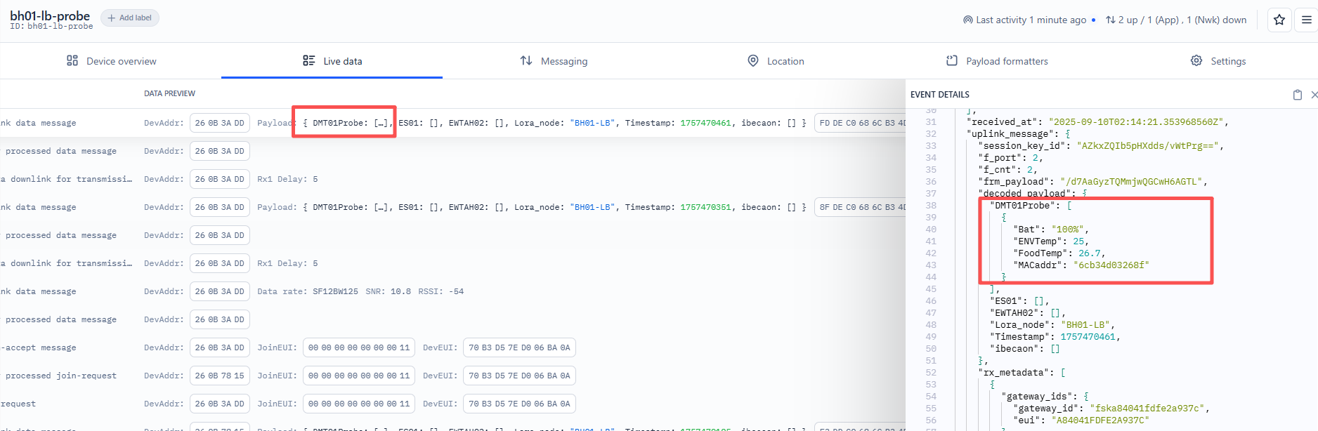
For example, the payload 0xD143A468C12309250F1A0406D000D10064CB equals 18 bytes.
Unit timestamp
Because the food temperature data is in little-endian format, the order of the bytes must be swapped during decoding.
Example (UNIX Timestamp): D143A468 (hex) = 68A443D1 (decimal)
Paste the decimal value into (https://www.epochconverter.com)) to get the corresponding time.
MACaddr
Example:
If the payload is C12309250F1A, the MACaddr is C12309250F1A
Working Mode
Example:
If the payload is 04, the BH01-LB/LS working mode is mode 4.
Please refer to this link for detailed instructions: BH01-LB/LS
Payload length
Example:
If the payload is 06, the payload is 6 bytes.
Food temperature
Because the food temperature data is in little-endian format, the order of the bytes must be swapped during decoding.
Example:
If the payload is D000 = 00D0(H), (00D0 & 8000 == 0), the temp =00D0H/10 = 208/10 = 20.8 ℃
If the payload is: BD80 = 80BD(H), (80BD & 8000 == 1), the **temp **= -(80BD & 7FFF)/10 = -189/10=-18.9 ℃.
Ambient temperature
Because the food temperature data is in little-endian format, the order of the bytes must be swapped during decoding.
Example:
If the payload is D100= 00D1(H), (00D1 & 8000 == 0), the temp =00D1H/10 = 209/10 = 20.9 ℃
Probe battery
Example:
If the payload is 0x64, the Probe battery = 100%
Probe RSSI
Note:
By default, this byte is not processed during decoding.
If desired, the backslash preceding the RSSI character can be removed during decoding.
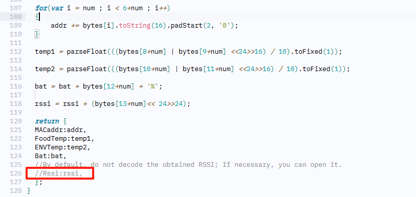
Example:
If the payload is 0xCB, the Probe RSSI = -53db
2.5.3 Important Notes
To ensure successful data capture and transmission via the BH01-LB device, please note the following important considerations:
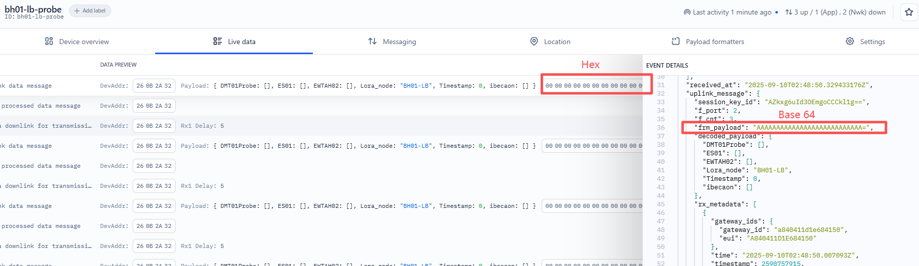
1. Connection Status Verification
The Bluetooth connection between the DMT01 relay box and the probe will only be disconnected when the distance between them exceeds the effective Bluetooth transmission range (typically around 35 meters in open space). Only when the connection is completely broken will the probe automatically switch to BLE broadcast mode, making it detectable by the BH01-LB device.
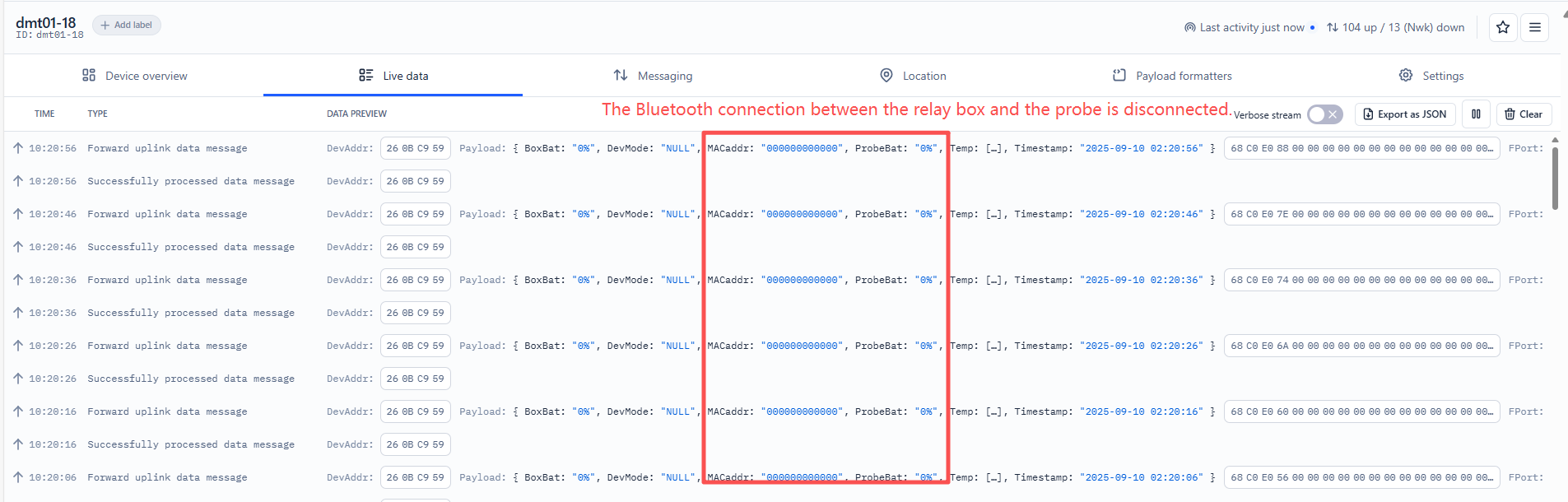
Indicator: When the DMT01 relay box and probe are disconnected, the LoRa uplink data from the DMT01 (except for the timestamp) will show all zeros, as illustrated in the figure below:
2. BH01-LB Bluetooth Scanning Behavior
The BH01-LB device activates its Bluetooth scanning function only during specific transmission events. Scanning occurs in the following situations:
- Periodic transmission: When the automatic uplink interval (configured via AT+TDC command, default: 20 minutes) is reached.
- Manual trigger: When the ACT button is pressed for 1-3 seconds.
- Device initialization: When the reset button is pressed to restart the device.
During these scanning windows, the BH01-LB searches for nearby BLE broadcast probe.
3. Empty Payload Handling
If the BH01-LB does not detect any probe during its scanning window, the uplink payload will consist entirely of zeros.
2.6 Datalog Feature
The Datalog feature ensures that the IoT Server can receive all sampling data from the sensor, even if the LoRaWAN network is down. For each sample, the DMT01 stores the reading for future retrieval.
2.6.1 How Datalog works
The DMT01 waits for an ACK for every uplink. If the LoRaWAN network is unavailable, the DMT01 marks these records as non-ACK messages, stores the sensor data, and sends all messages at 10-second intervals after network recovery.
a) The DMT01 performs an ACK check for each data record to ensure that every piece of data reaches the server.
b) The DMT01 sends data in CONFIRMED Mode, but it will not re-transmit a packet if an ACK is not received; instead, it marks it as a NON-ACK message. In a future uplink, if the DMT01 receives an ACK, it assumes the network connection is restored and resends all NON-ACK messages
2.6.2 Enable Datalog
Using the platform downlink 07 01, you can enable the device to automatically send non-ACK messages. Once enabled, the LC01 will wait for an acknowledgment (ACK) for every uplink. If the LoRaWAN network is unavailable, the DMT01 will mark these records as non-ACK messages, store the sensor data, and continue checking for network availability at 10-second intervals to resend all stored messages once the network is restored.
a) The DMT01 performs an ACK check for each data record to ensure it successfully reaches the server.
b) When automatic sending of non-ACK messages is enabled, the DMT01 transmits data in CONFIRMED mode. If an ACK is not received, it does not resend the packet; instead, it marks it as a non-ACK message. During subsequent uplinks, if the DMT01 receives an ACK, it considers the network restored and will resend all stored non-ACK messages.
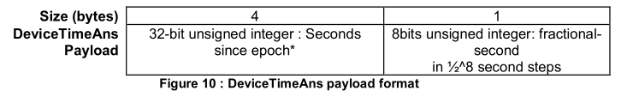
2.6.3 Unix Timestamp
DMT01 uses Unix Timestamp based on the following format.
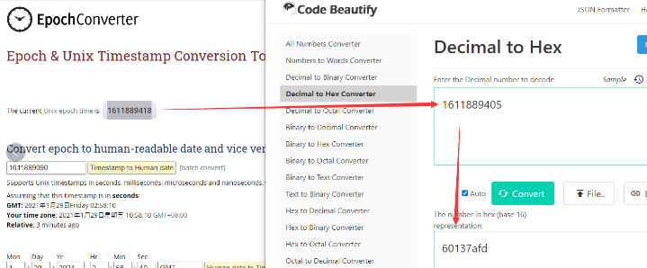
You can get the current UNIX epoch time from link, https://www.epochconverter.com/ . Once you have the UNIX epoch time, convert it to hex using a decimal to hex converter, for example using Code Beautify.
Below is the graphical example of how to do that:
2.6.4 Set Device Time
You need to run downlink command 28 01 to enable time synchronization.
Once the LC01 joins the LoRaWAN network, it will send the MAC command DeviceTimeReq, and the server will reply with DeviceTimeAns to provide the current time to the LC01. If the LC01 fails to receive the time from the server, it will use its internal time and wait for the next time request. (By default, this occurs once every 10 days.)
Information
The LoRaWAN network server must support LoRaWAN v1.0.3 (MAC v1.0.3) or higher to use this MAC command feature. ChirpStack, The Things Stack v3, and Loriot support it, but The Things Stack v2 does not. If the network server does not support this command, it will discard the uplink packet containing it. As a result, the user will lose the time request packet when the automatic time synchronization function is enabled on TTN v2.
Downlink Command: 0x28
- Example: 0x28 01 // Automatic time synchronization Enabled
- Example: 0x28 00 // Automatic time synchronization Disable.
2.6.5 Datalog Uplink payload (FPort=3)
The Datalog uplinks use the following payload format.
Retrieval data payload:
| Size(bytes) | 4 | 1 | 6 | 1 | 1 | 1 | 1 | 2 | 2 |
|---|---|---|---|---|---|---|---|---|---|
| Value | Timestamp | DevMode | MACaddr | ProbeBat | BoxBat | Message Type | tempData Length | Food temperature | Ambient temperature |
No ACK Message: This message indicates that the payload is from an uplink message that did not receive an ACK from the server previously (for the PNACKMD=1 feature).
Poll Message Flag: 1: This message indicates a poll message reply.
-
Poll Message Flag is set to 1.
-
Each data entry is 11 bytes, to save airtime and battery, devices will send max bytes according to the current DR and Frequency bands.
For example, in US915 band, the max payload for different DR is:
a) DR0: max is 11 bytes so one entry of data
b) DR1: max is 53 bytes so devices will upload 4 entries of data (total 44 bytes)
c) DR2: total payload includes 11 entries of data
**d) DR3: **total payload includes 22 entries of data.
If the device doesn't have any data in the polling time, it will uplink 11 bytes of 0
For example, if you send the downlink command, 316892FD706893103005, the Start time and Stop time bytes as follows.
- Start time: 6892FD70 = time 25/8/6 07:00:00
- Stop time: 68931030 = time 25/8/6 08:20:00
For example, consider the DMT01 uplinks the following payload:
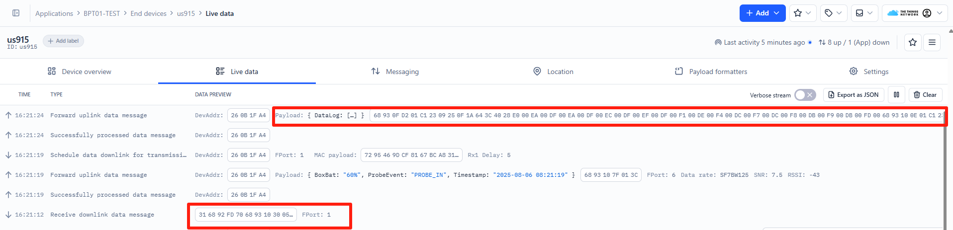
68930FD201C12309250F1A643C4028E000EA00DF00EA00DF00EC00DF00EF00DF00F100DE00F400DC00F700DC00F800DB00F900DB00FD00
6893100E01C12309250F1A643C4028DE000401FF00090105010D0103011001030112011A011401150115010E0117010A01170104011801
Where the first 55 bytes is for the first entry:
68930FD2 01 C12309250F1A 64 3C 40 28 E000 EA00 DF00 EA00 DF00 EC00 DF00 EF00 DF00 F100 DE00 F400 DC00 F700 DC00 F800 DB00 F900 DB00 FD00
Unix time is 0x68930FD2=1754468306s=25/8/6 08:18:00
DevMode is 0x01 = BLE_LoRa
**MACaddr **is 0xC12309250F1A = C12309250F1A
**ProbeBat **is 0x64 = 100%
**BoxBat **is 0x3c = 60%
Message Type is 0x40 = POLL_REPLY
**tempDataLength **is 0x28 = 40(Represents the total number of temperature bytes of the current group)
Food temperature is 0xE000 = 00E0/10 = 22.4℃
Ambient temperature is 0xEA00 = 0x00EA/10=23.4℃
Food temperature is 0xDF00 = 00FD/10 = 25.3℃
Ambient temperature is 0xEA00 = 0x00EA/10=23.4℃
One set of data contains 10 sets of data, and so on...
2.7 DMT01 Working Mode (Relay Box)
Note: Since DMT01_BLE firmware v1.0.5 & DMT01_LoRa firmware v1.0.3, for details, please refer to FAQ 5.2.
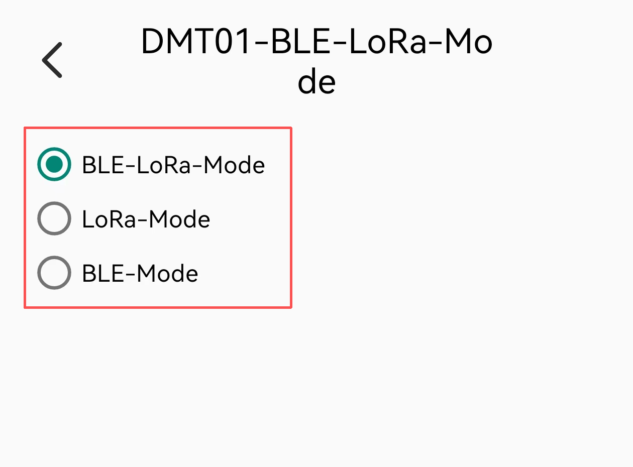
The DMT01 relay/charging box supports three operating modes:
- BLE/LoRa Mode (Default): Relay box provides simultaneous Bluetooth broadcast and LoRaWAN connectivity.
- LoRa-Only Mode: Relay box provides LoRaWAN communication only.
- BLE-Only Mode: Relay box provides Bluetooth broadcast only.
Important: The temperature probe operates independently and continuously broadcasts via Bluetooth. The probe connects to the relay box through Bluetooth communication.
2.7.1 Mode Switching Methods
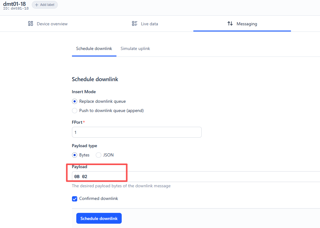
2.7.1.1 LoRaWAN Downlink Command
Switch relay box modes via LoRaWAN downlink command:
| **Command ** | ** Relay Box Mode** |
|---|---|
| 0x0B 0x01 | BLE/LoRa Mode |
| 0x0B 0x02 | LoRa-Only Mode |
| 0x0B 0x03 | BLE-Only Mode |
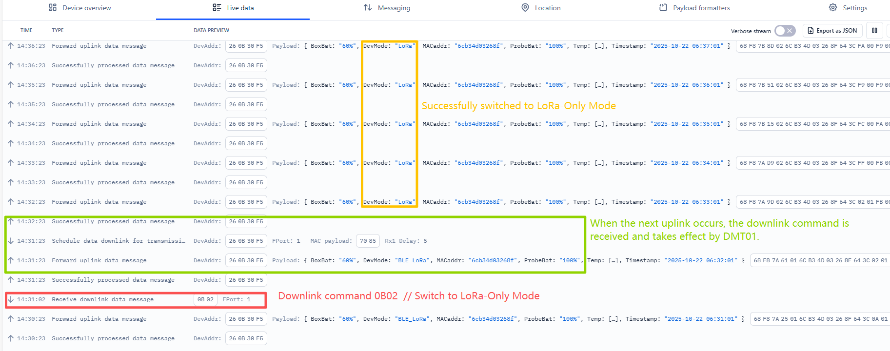
Example in TTN:
2.7.1.2. Bluetooth Configuration (Devices.tool APP)
To download the software, please click: Devices.tool APP V1.11.0 or later
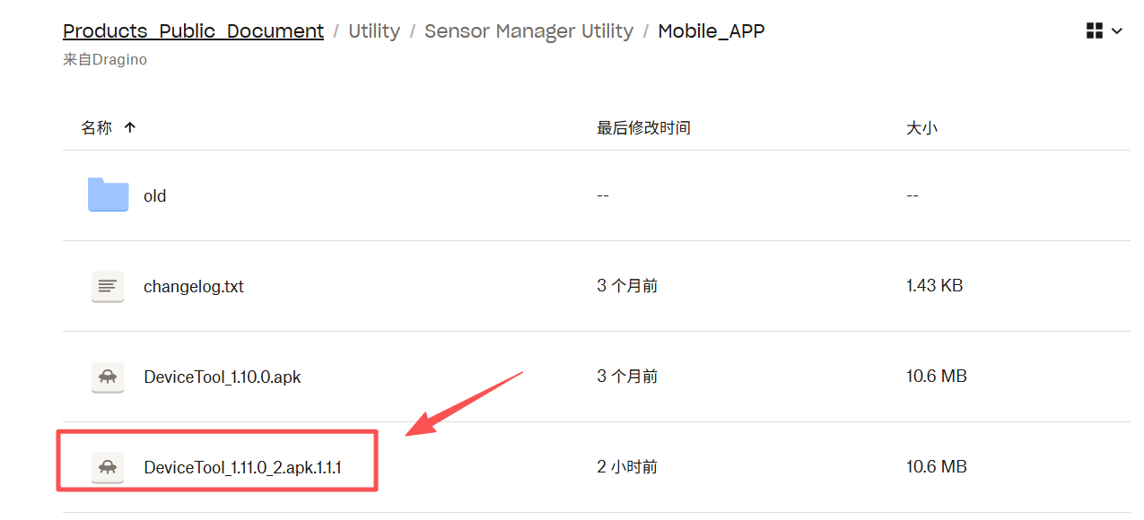
Note: This software is only applicable to Android phones.
Switch relay box modes via Bluetooth configuration:
① Open Devices.tool APP
② Tap the three dots in the upper right corner
③ Select "DMT01config"
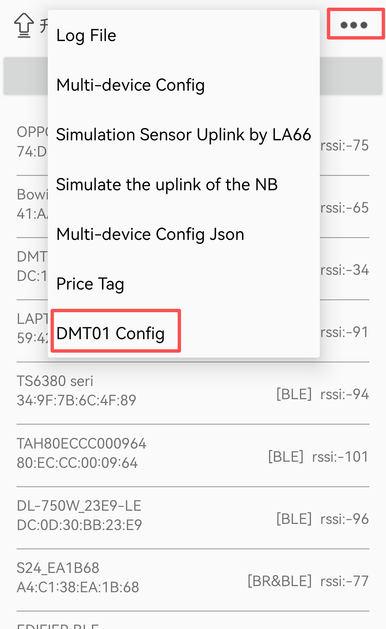
④ Scan and connect to the device
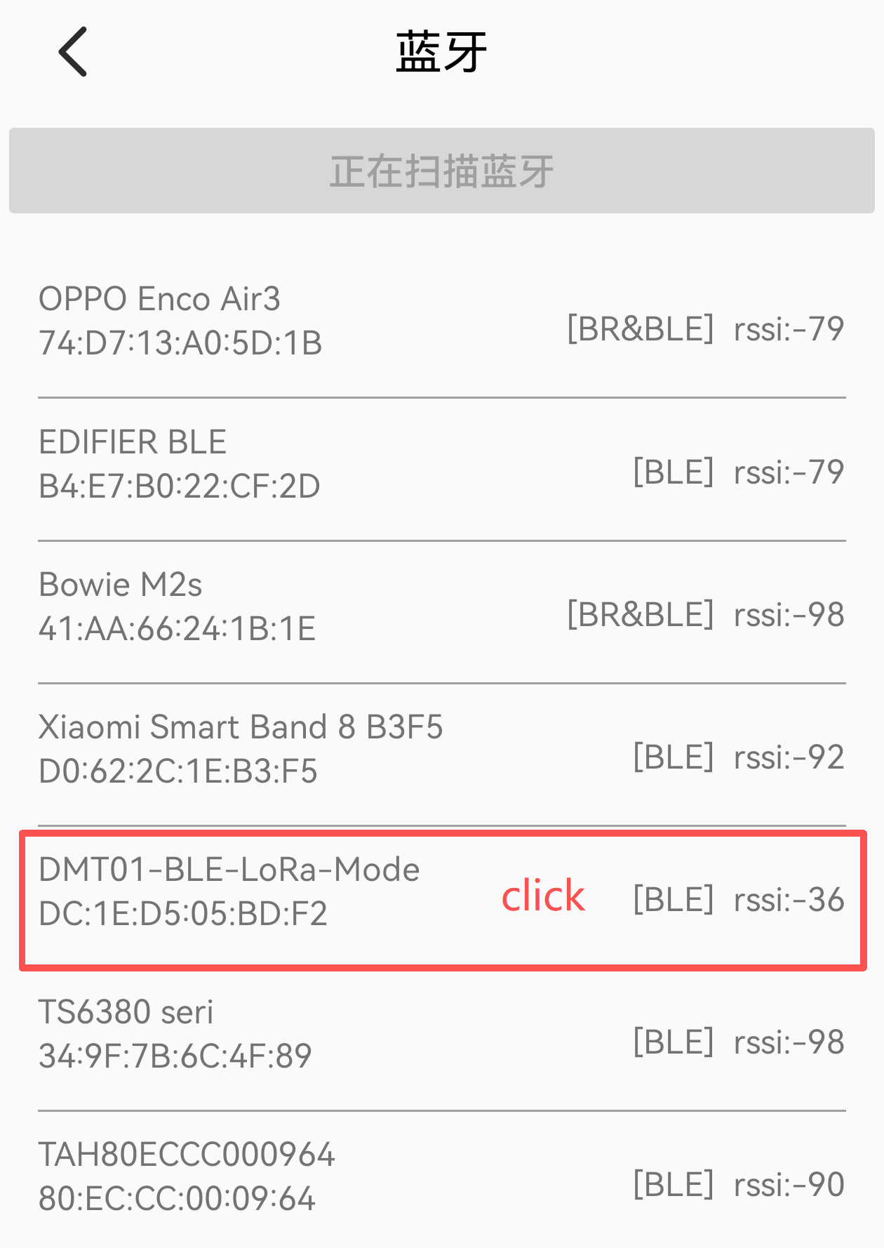
⑤ Configure the operating mode
⑥ After completing Bluetooth configuration, please disconnect the Bluetooth connection.
Note: When switching relay box modes, the LED will show solid red for 3 seconds to indicate successful mode change.
2.7.2 Bluetooth Broadcast Names
| **Relay Box Mode ** | Bluetooth Broadcast Name |
|---|---|
| BLE/LoRa Mode | DMT01-BLE-LoRa-Mode |
| BLE-Only Mode | DMT01-BLE-Mode |
Note:
- For relay box Bluetooth configuration and OTA updates, connect using the broadcast names listed above.
- No matter if it's for the relay box's Bluetooth configuration, downlink configuration, or OTA updates, the probe must be removed.
3. Configure DMT01
The DMT01 supports the following configuration method:
- LoRaWAN Downlink: For instructions on different platforms, see the IoT LoRaWAN Server section.
3.1 General Commands
These commands are to configure:
- General system settings like: uplink interval.
- LoRaWAN protocol & radio related command.
They are same for all Dragino Devices which support DLWS-005 LoRaWAN Stack. These commands can be found on the wiki:
/docs/wiki/Configuration/end-node/at-commands-downlink/
Note: DMT01 can only be configured using Downlink commands and does not support configuration using AT commands.
3.2 Downlink Commands Set
These commands are valid only for the DMT01.
3.2.1 Set Transmit Interval Time
Feature: Set the LoRaWAN end device's transmit Interval. Also known as TDC time.
AT Command:
There is no AT command to set TDC time.
Downlink Command: 0x01
Format: Command Code (0x01) followed by 3 bytes time value.
If the downlink payload is 0100003C, it means the end device's transmit Interval is set to 0x00003C = 60 seconds, with the type code 0x01.
- Example 1: Downlink Payload: 0100001E // Sets the transmit interval (TDC) to 30 seconds
- Example 2: Downlink Payload: 0100003C // Sets the transmit interval (TDC) to 60 seconds
3.2.2 Get Device Status
Feature: Send a LoRaWAN downlink to request the device's status.
Downlink Payload: 0x26 01
The end device will upload device status via FPort=5. See the payload section for details.
3.2.3 Clear Flash Record
Feature: Clear flash storage for the data log feature.
AT Command:
There is no AT command to clear flash storage for the data log feature
Downlink Command: 0x08
- Example: 0x0801 // Clears all saved data in flash.
3.2.4 Confirmed Mode
Feature: Mode for sending data that requires acknowledgment.
AT Command:
There is no AT command to control whether Confirmed Mode is enabled or disabled.
Downlink Command: 0x07
- Example: 0x07 01 // Enable the confirmed mode.
- Example: 0x07 00 // Disabled the confirmed mode.
3.2.5 Set the synchronization time interval
Feature: Set how often time synchronization is performed (default: 10 days; unit: days).
Downlink Command: 0x28
- Example: 0x28 01 // Synchronize once a day
- Example: 0x28 03 // Synchronize once every three days
3.2.6 Alarm Mode
Feature: When the sampled food temperature falls below or exceeds the set thresholds, the device will automatically trigger an alarm. (The alarm mode applies only to the food probe temperature.)
Downlink Command: 0x09
Format: Command Code (0x09) followed by 4 bytes.
Example: 09 aa aa bb bb
| Parameter | Function |
|---|---|
| aa aa | Minimum temperature threshold (Minimum must not be lower than -30℃) |
| bb bb | Maximum temperature threshold (Maximum must not be higher than 110℃) |
Example 1 : 0x09 00 64 03 84
Minimum Threshold = 0x0064 (100) → 100 / 10 = 10.0°C
Maximum Threshold = 0x0384 (900) → 900 / 10 = 90.0°C
Example 2 : 0x09 00 00 00 00 // Disable threshold alarm mode
Note:
- When the temperature exceeds the set minimum or maximum thresholds, sampling will be performed at 6-second intervals. Each set of temperature data will be immediately uploaded to the server.
- The minimum and maximum alarm temperatures must be within the food temperature range of -30 °C to 110 °C.
3.2.7 Multi sampling
Feature: Perform multiple samples and upload the data together in a single transmission.
Downlink Command: 0x0A
Format: Command Code (0x0A) followed by 3 bytes.
Example: 0A aa aa bb
| Parameter | Function |
|---|---|
| aa aa | Sampling interval (range: 6~65535s) |
| bb | Sampling times (range: 1~12 times) |
Example: 0x0A 00 06 0A //Default configuration. Sampling occurs once every 6 seconds, and data is uploaded after 10 samples (i.e., uploading occurs once every 1 minute).
4. Firmware update
The user can upgrade the firmware of the DMT01 charger/repeater box. The charger/repeater box includes two pieces of software
-
LoRa part: OTA firmware update via LoRa.
-
BLE and controller part:
4.1 Update LoRa software
he user can update the DMT01 charger firmware to:
- Change the frequency band/region.
- Add new features.
- Fix bugs.
Firmware and the changelog can be downloaded from : Firmware download link
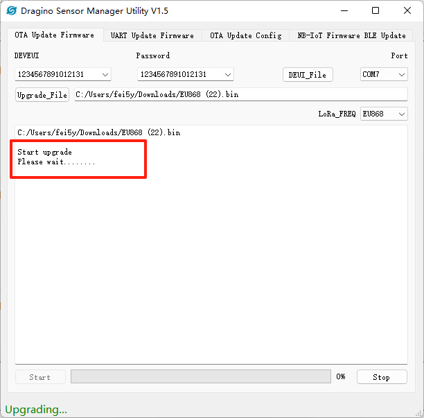
Methods to Update Firmware:
- OTA firmware update wirelessly : Firmware OTA Update for LoRaWAN End Node
**Note: During the OTA update process, if the OTA Update Tool displays "Please wait...", remove the temperature probe and press the button for 3 seconds to reset the DMT01 charger/repeater box. This will allow the update tool to connect to the DMT01 charger/repeater box more quickly. **
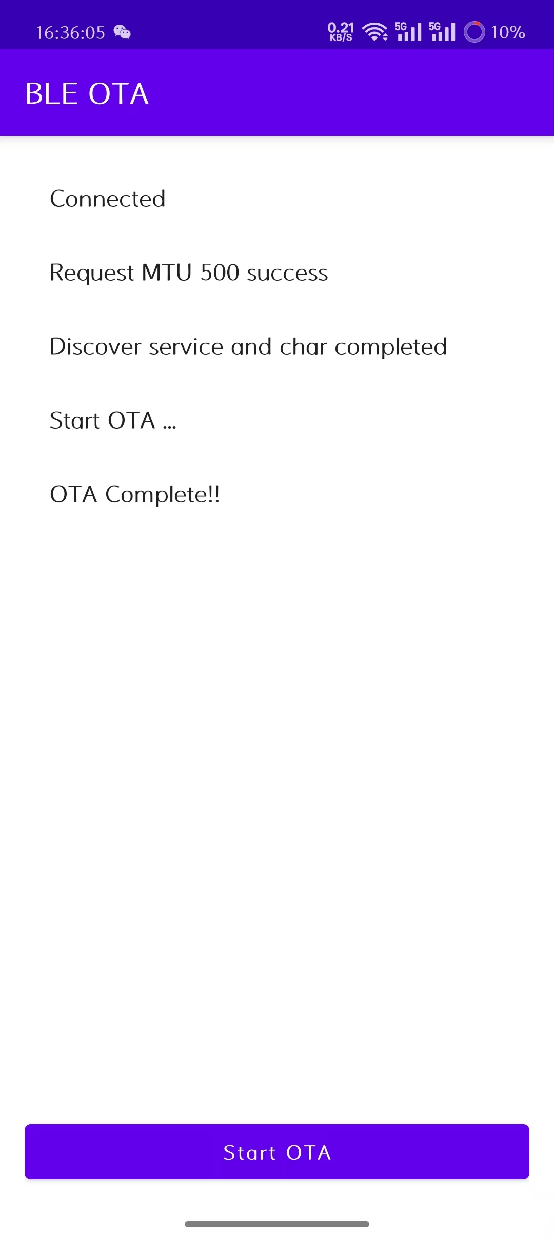
4.2 Update BLE software
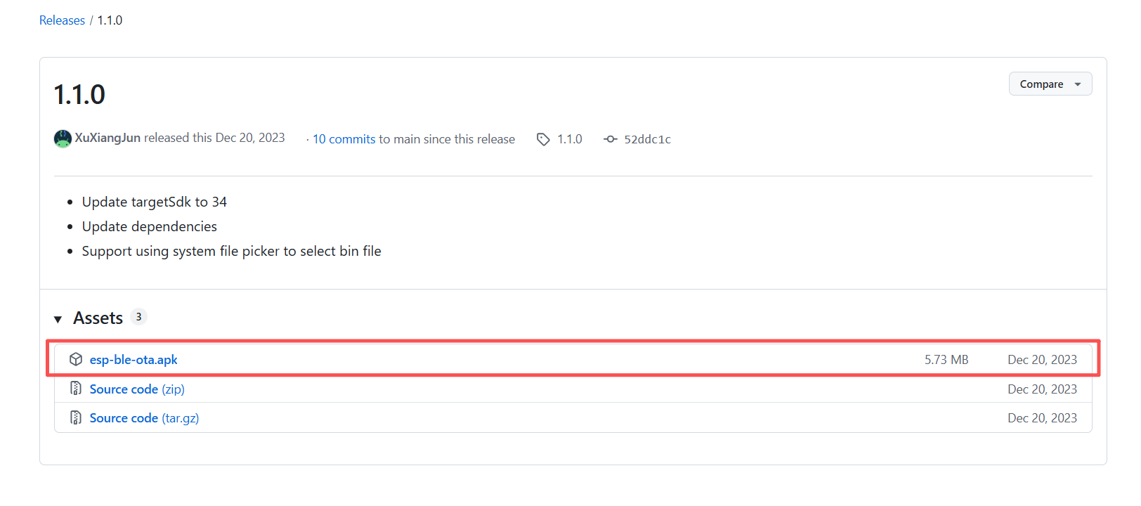
Step 1:
- Download the app EspBleOTA on your mobile phone.
- Download link for the APK file (Android): APK file
Step 2:
- After installing the app on your phone, open EspBleOTA.
Note:
1. This tool is only available for Android phones.
2. When you open the app, it will request permission to use your phone's Bluetooth. Please grant permission when prompted. Otherwise the app will not be able to search for Bluetooth devices.
3. You need to pull down the scan display window to rescan for BLE devices.
Step 3:
- Select the Bluetooth device named DMT01 in the scan display window and click to connect.
Note: Before upgrading, you need to save the firmware in the directory of the phone. When upgrading, you need to enter the saved path and select the firmware.
Step 4:
- Wait until the update is complete.
5. FAQ
5.1 Why can't I get dynamic temperature data from the K10-BTS-P probe?
Currently, the K10-BTS-P probe (software version VX1.0.0.3) only performs dynamic temperature measurement when it maintains a Bluetooth connection with the DMT01 relay box. Once the probe disconnects from the relay box, temperature sampling stops, and the temperature data remains unchanged from the value at the moment of disconnection.
To enable the probe to continue temperature measurement and provide dynamic data even during Bluetooth broadcast mode (when disconnected from the relay box), you need to upgrade the probe firmware from VX1.0.0.3 to** VX1.0.0.4**.
How to Upgrade K10-BTS-P Probe
1. Download Required Software and Firmware
- Mobile tool for firmware upgrade: SUOTA APP (Applicable only to Android phones)
Download link: SUOTA
- K10-BTS-P Firmware File
Download link: K10-BTS-P-OTA-VX1.0.0.4
2. Upgrade Steps:
We also provide an operational video demonstration to help you better understand the upgrade process. You can watch it here: K10-BTS-P Probe Upgrade Operation Video
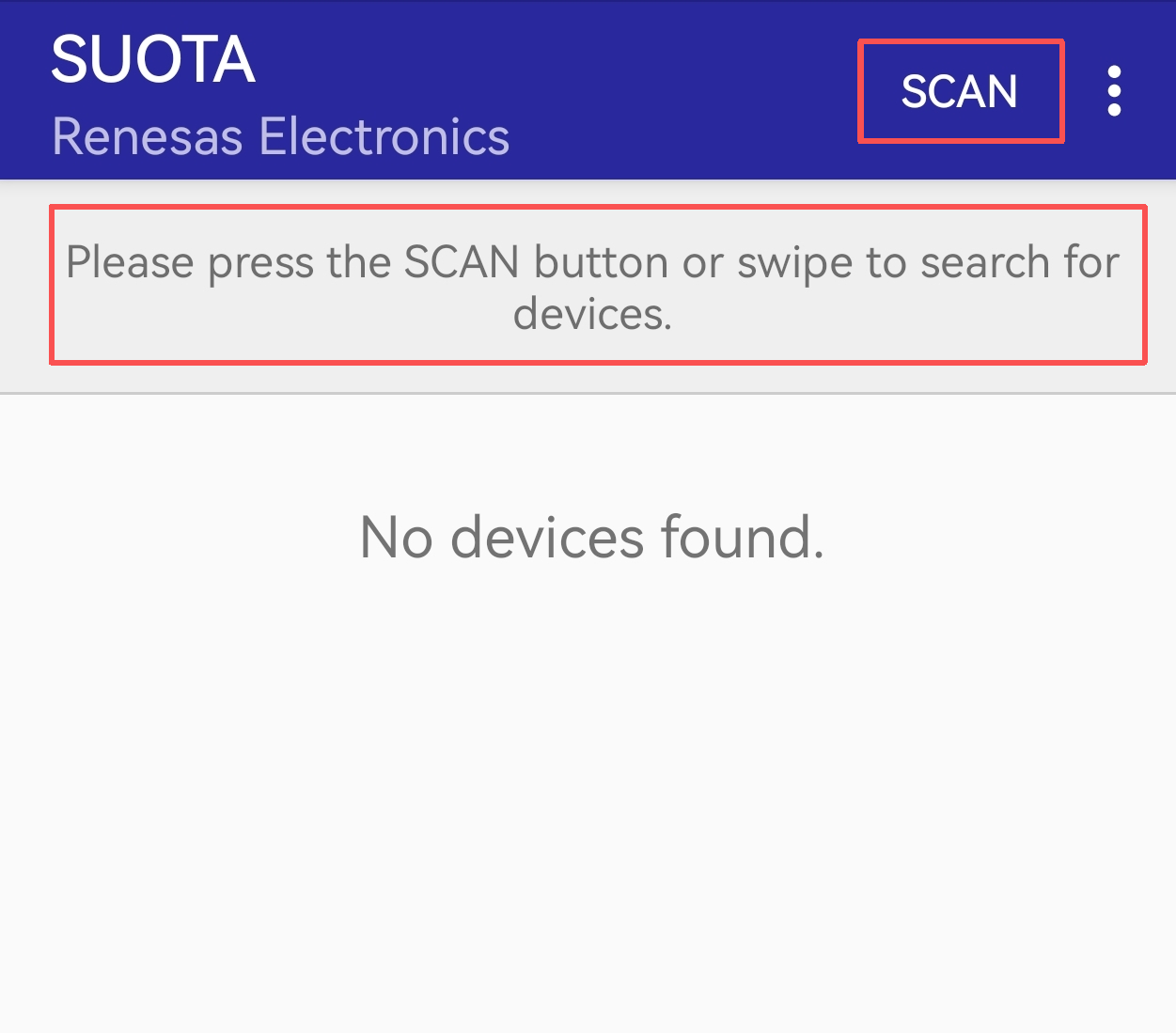
- Install and open the SUOTA upgrade tool.
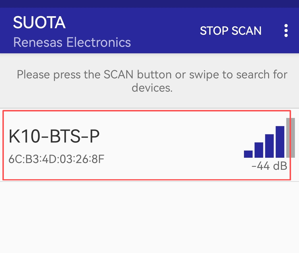
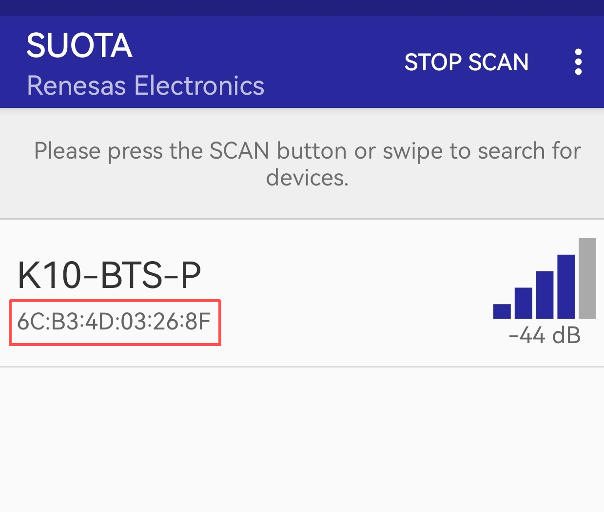
- Tap the "SCAN" button in the upper right corner to scan for the probe.
Note: Ensure the probe is disconnected from the DMT01 relay box and not connected to any other Bluetooth tools.Applicable only to Android phones
- Select the scanned K10-BTS-P probe from the list to connect.
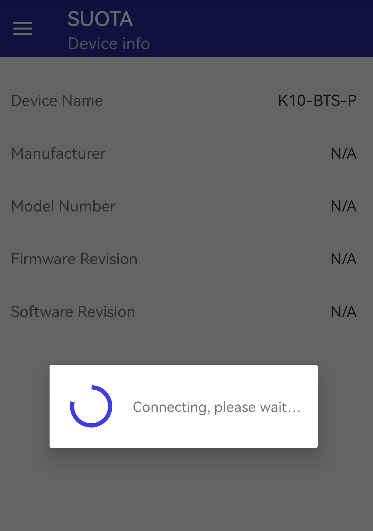
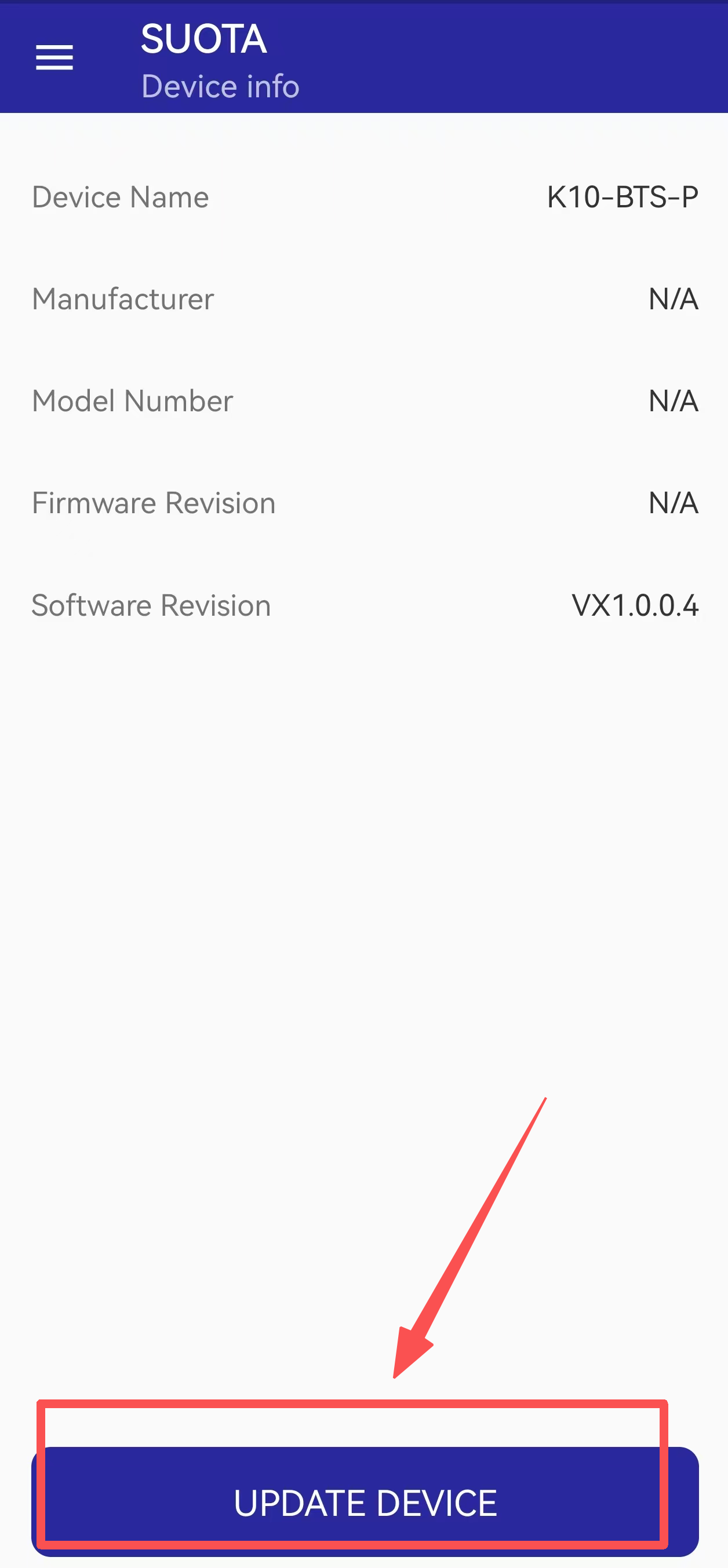
- After successful connection, tap "UPDATE DEVICE".
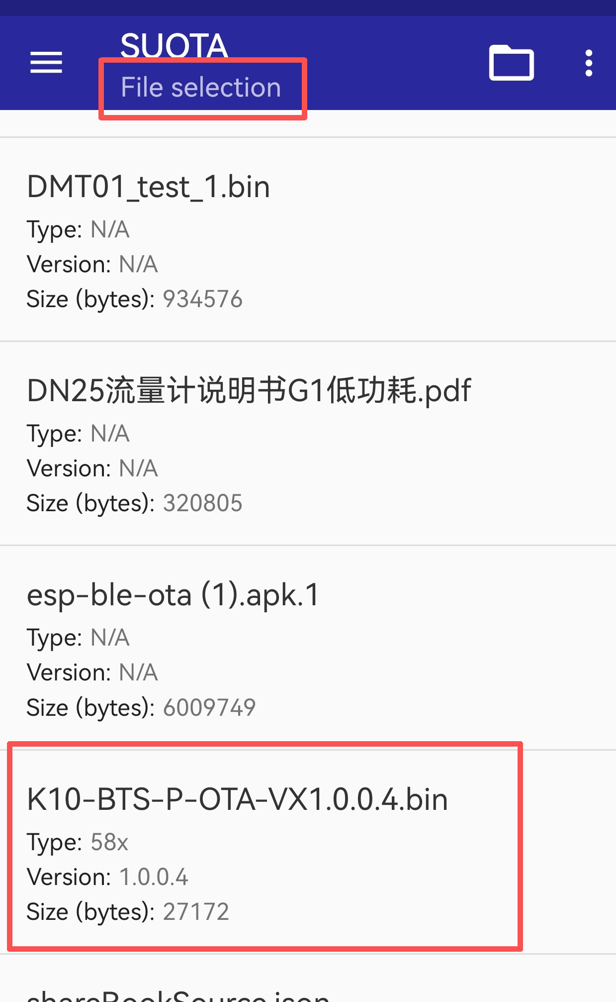
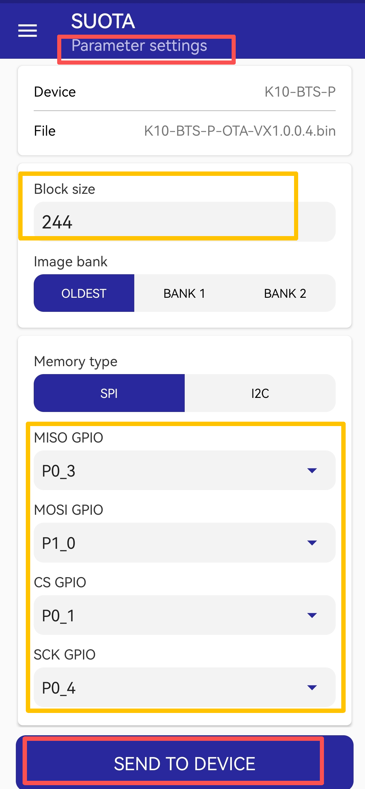
- Select the firmware file: K10-BTS-P-OTA-VX1.0.0.4.bin.
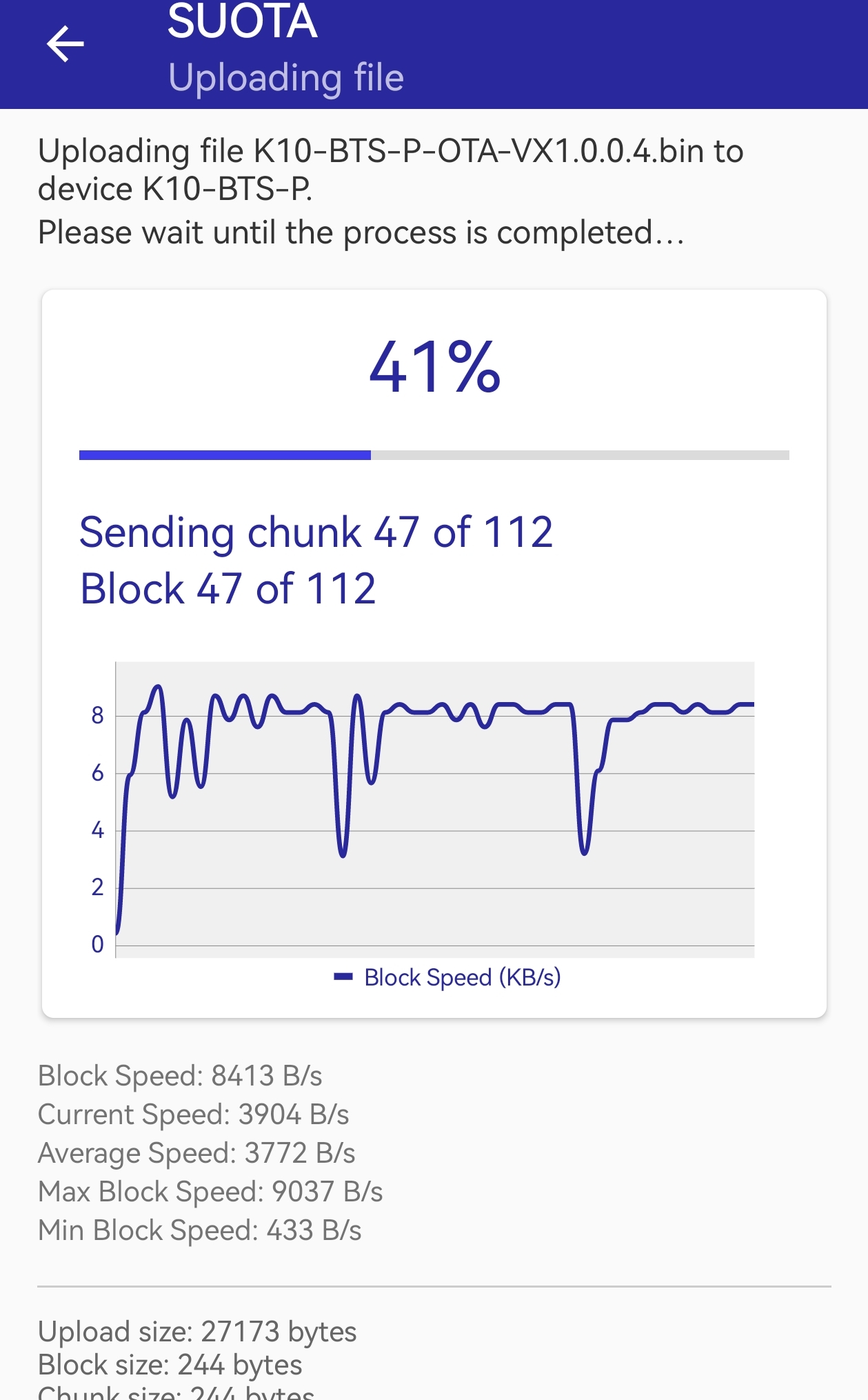
- Configure the upgrade parameters and Tap "SEND TO DEVICE" to start the upgrade.
(Please refer to the screenshot for parameter settings)
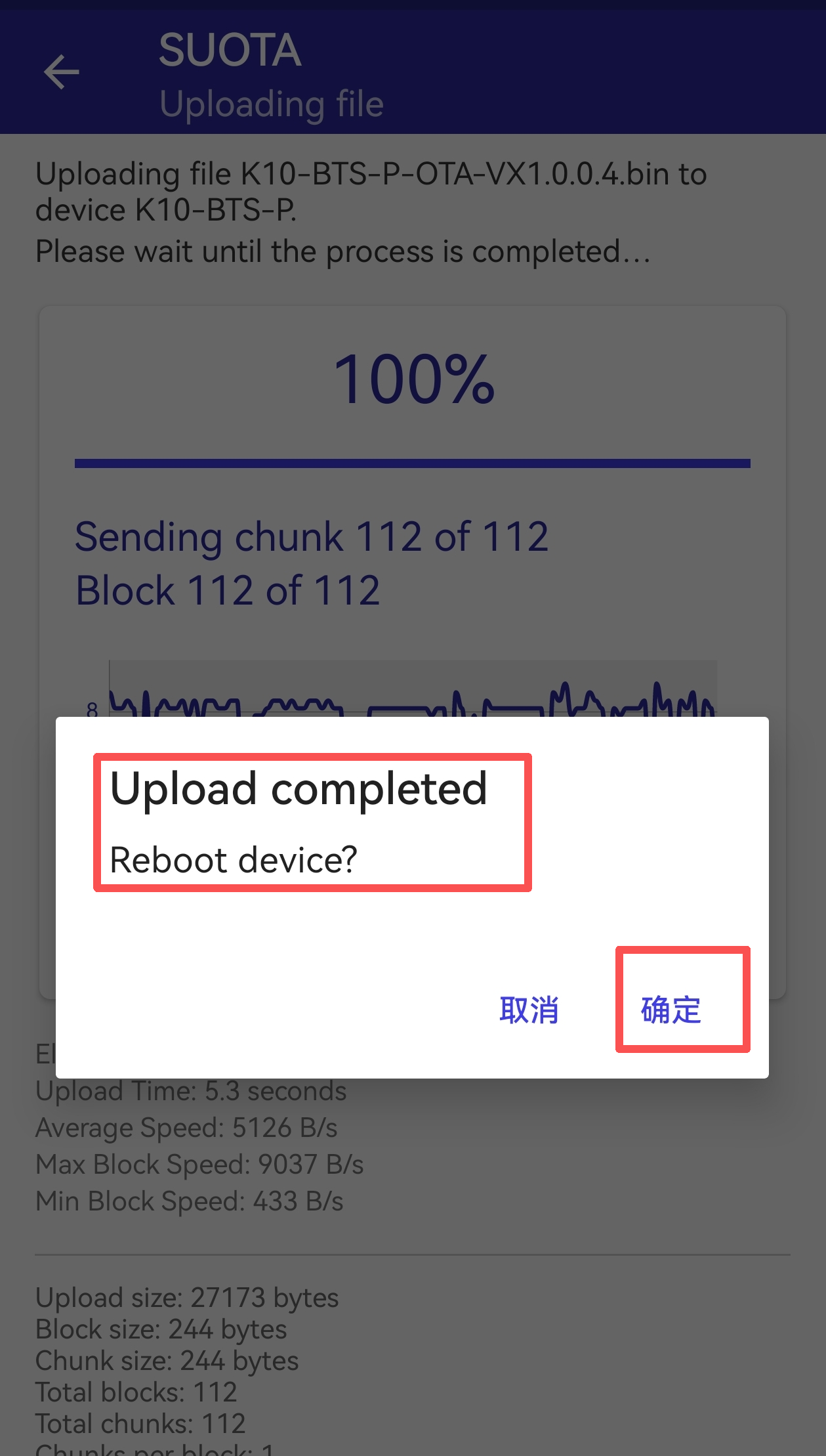
- Once the upgrade is complete, a confirmation dialog will appear. Tap "Confirm" to reboot the device.
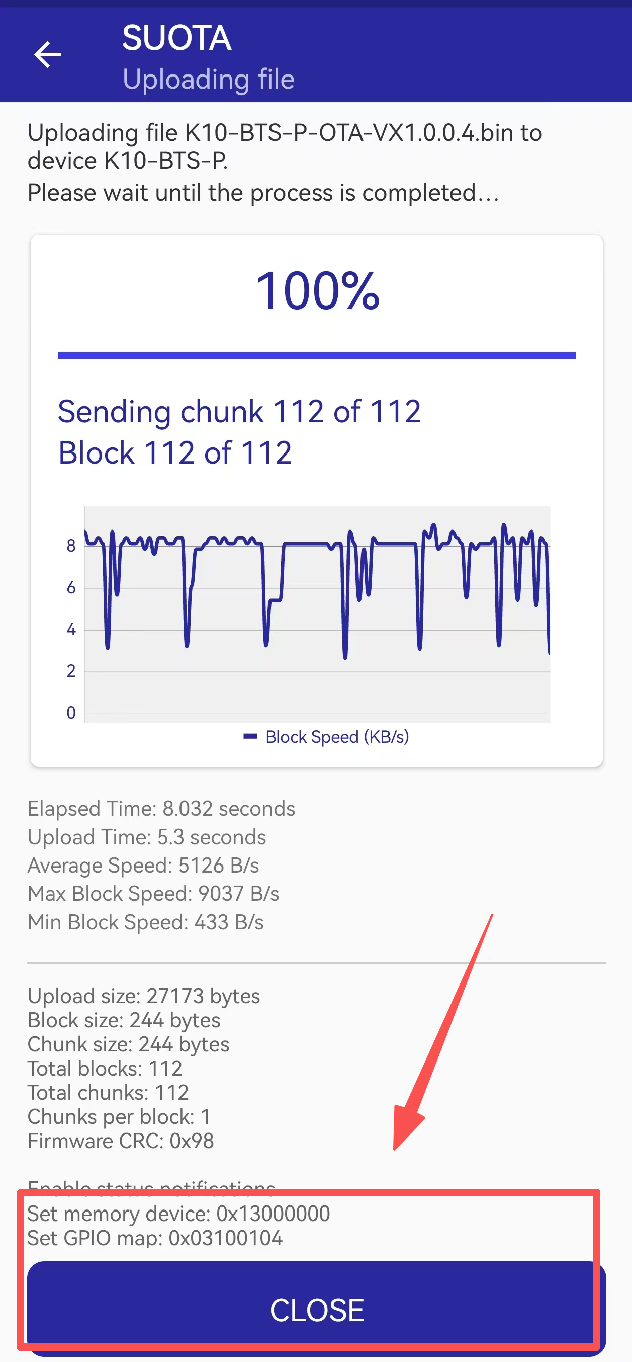
- Tap "CLOSE" to exit. SUOTA will automatically disconnect from the probe.
3. Verify the Upgrade
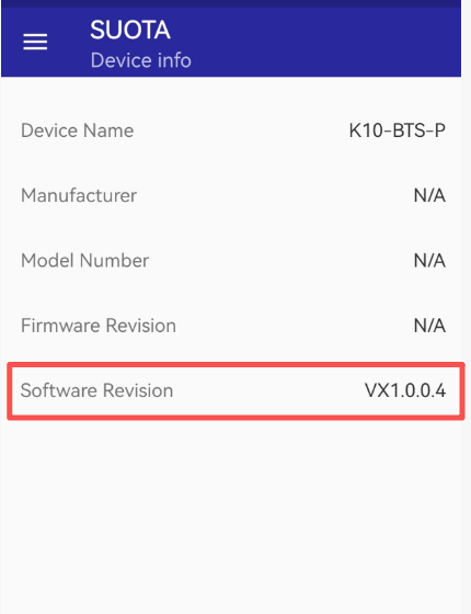
After tapping "CLOSE", SUOTA will automatically return to the scanning screen.
Locate the probe that was just upgraded (you can identify it by the probe's MAC address).
Tap to connect to the probe again.
Once connected successfully, SUOTA will display the current software version of the probe, as shown in the screenshot below: Confirm that the version displayed is VX1.0.0.4.
4. Post-Upgrade Verification of Dynamic Temperature Data:
After the successful upgrade, the K10-BTS-P probe will continuously measure temperature even when in Bluetooth broadcast mode (disconnected from the relay box).
For example, using the nRF Connect Bluetooth tool to scan for the probe in broadcast mode will show real-time changes in temperature data, as demonstrated in the animated illustration below:
5.2 Why can't I switch the working mode via LoRaWAN downlink or BLE configuration?
If you are unable to switch the DMT01's working mode using LoRaWAN downlink commands or BLE configuration, it is most likely because your device is running an older version of the firmware.
Reason: In previous firmware versions, the operating mode could only be switched using the physical button on the relay box. To prevent accidental mode changes caused by unintended button presses, we removed the button-switching function and introduced remote switching via LoRaWAN and BLE in the firmware update.
Solution:
1. Firmware Version Requirement
You need to upgrade your device firmware to a version that supports this feature. The functionality is available starting from:
- DMT01_BLE firmware v1.0.5
- DMT01_LoRa firmware v1.0.3
How to check your firmware version: You can easily identify which firmware your device has by checking its Bluetooth broadcast name during a scan:
| **Bluetooth Device Name ** | ** Firmware Version ** | Supports LoRa/BLE Mode Switching? |
|---|---|---|
| DMT01 | Old Firmware | No - Firmware upgrade required. |
| DMT01-BLE-LoRa-Mode or DMT01-BLE-Mode | New Firmware (v1.0.5/v1.0.3 or above) | Yes - You can switch modes via LoRaWAN downlink or BLE configuration. |
2. Configuration Tool Version Requirement
To perform the mode switching via BLE configuration, you must use **DeviceTool ** version V1.11.0 or later. Earlier versions of the tool do not support this new functionality.
6. Order Info
Part Number: DMT01-XX
XX:
- EU433: Frequency bands EU433
- EU868: Frequency bands EU868
- KR920: Frequency bands KR920
- CN470: Frequency bands CN470
- AS923: Frequency bands AS923
- AU915: Frequency bands AU915
- US915: Frequency bands US915
- IN865: Frequency bands IN865
- CN779: Frequency bands CN779
7. Packing Info
Package Includes:
- DMT01 - Digital Meat Thermometer x 1
Dimension and weight:
- Package Size / pcs : 190*80*50mm
- Weight / pcs : 310g
8. Support
- Support is available Monday to Friday, from 09:00 to 18:00 GMT+8. Due to different time zones, we cannot offer live support. However, your questions will be answered as soon as possible within the above-mentioned schedule.
- Please provide as much information as possible regarding your inquiry (product models, a detailed description of the problem, and steps to reproduce it) and send an email to support@dragino.com.
0