RS485-LN
1. Introduction
1.1 What is RS485-LN RS485 to LoRaWAN Converter
The Dragino RS485-LN is a RS485 to LoRaWAN Converter. It converts the RS485 signal into LoRaWAN wireless signal which simplify the IoT installation and reduce the installation/maintaining cost.
RS485-LN allows user to monitor / control RS485 devices and reach extremely long ranges. It provides ultra-long range spread spectrum communication and high interference immunity whilst minimizing current consumption. It targets professional wireless sensor network applications such as irrigation systems, smart metering, smart cities, building automation, and so on.
For data uplink, RS485-LN sends user-defined commands to RS485 devices and gets the return from the RS485 devices. RS485-LN will process these returns according to user-define rules to get the final payload and upload to LoRaWAN server.
For data downlink, RS485-LN runs in LoRaWAN Class C. When there downlink commands from LoRaWAN server, RS485-LN will forward the commands from LoRaWAN server to RS485 devices.
Demo Dashboard for RS485-LN connect to two energy meters: https://app.datacake.de/dashboard/d/58844a26-378d-4c5a-aaf5-b5b5b153447a
1.2 Specifications
Hardware System:
- STM32L072xxxx MCU
- SX1276/78 Wireless Chip
- Power Consumption (exclude RS485 device):
- Idle: 32mA@12v
- 20dB Transmit: 65mA@12v
Interface for Model:
- RS485
- Power Input 7~ 24V DC.
LoRa Spec:
- Frequency Range:
- Band 1 (HF): 862 ~ 1020 Mhz
- Band 2 (LF): 410 ~ 528 Mhz
- 168 dB maximum link budget.
- +20 dBm - 100 mW constant RF output vs.
- +14 dBm high efficiency PA.
- Programmable bit rate up to 300 kbps.
- High sensitivity: down to -148 dBm.
- Bullet-proof front end: IIP3 = -12.5 dBm.
- Excellent blocking immunity.
- Low RX current of 10.3 mA, 200 nA register retention.
- Fully integrated synthesizer with a resolution of 61 Hz.
- FSK, GFSK, MSK, GMSK, LoRaTM and OOK modulation.
- Built-in bit synchronizer for clock recovery.
- Preamble detection.
- 127 dB Dynamic Range RSSI.
- Automatic RF Sense and CAD with ultra-fast AFC.
- Packet engine up to 256 bytes with CRC
1.3 Features
- LoRaWAN Class A & Class C protocol (default Class C)
- Frequency Bands:
CN470、EU433、KR920、US915、EU868、AS923、AU915、IN865、RU864、MA869 - AT Commands to change parameters
- Remote configure parameters via LoRa Downlink
- Firmware upgradable via program port
- Support multiply RS485 devices by flexible rules
- Support Modbus protocol
- Support Interrupt uplink (Since hardware version v1.2)
1.4 Applications
- Smart Buildings & Home Automation
- Logistics and Supply Chain Management
- Smart Metering
- Smart Agriculture
- Smart Cities
- Smart Factory
1.5 Firmware Change log
RS485-LN Image files – Download link and Change log
1.6 Hardware Change log
v1.2: Add External Interrupt Pin.
v1.0: Release
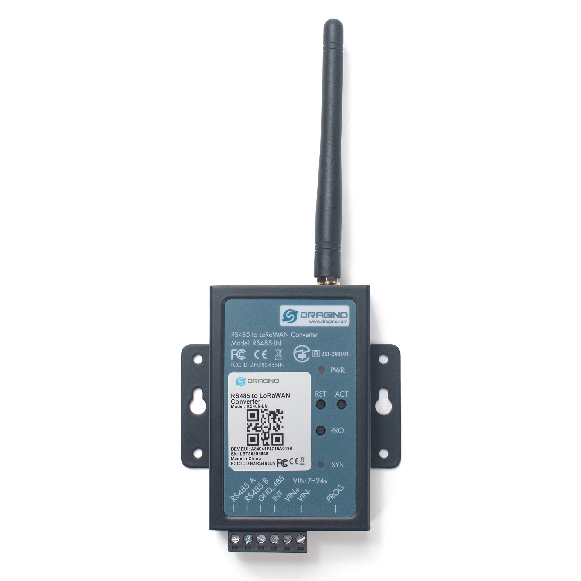
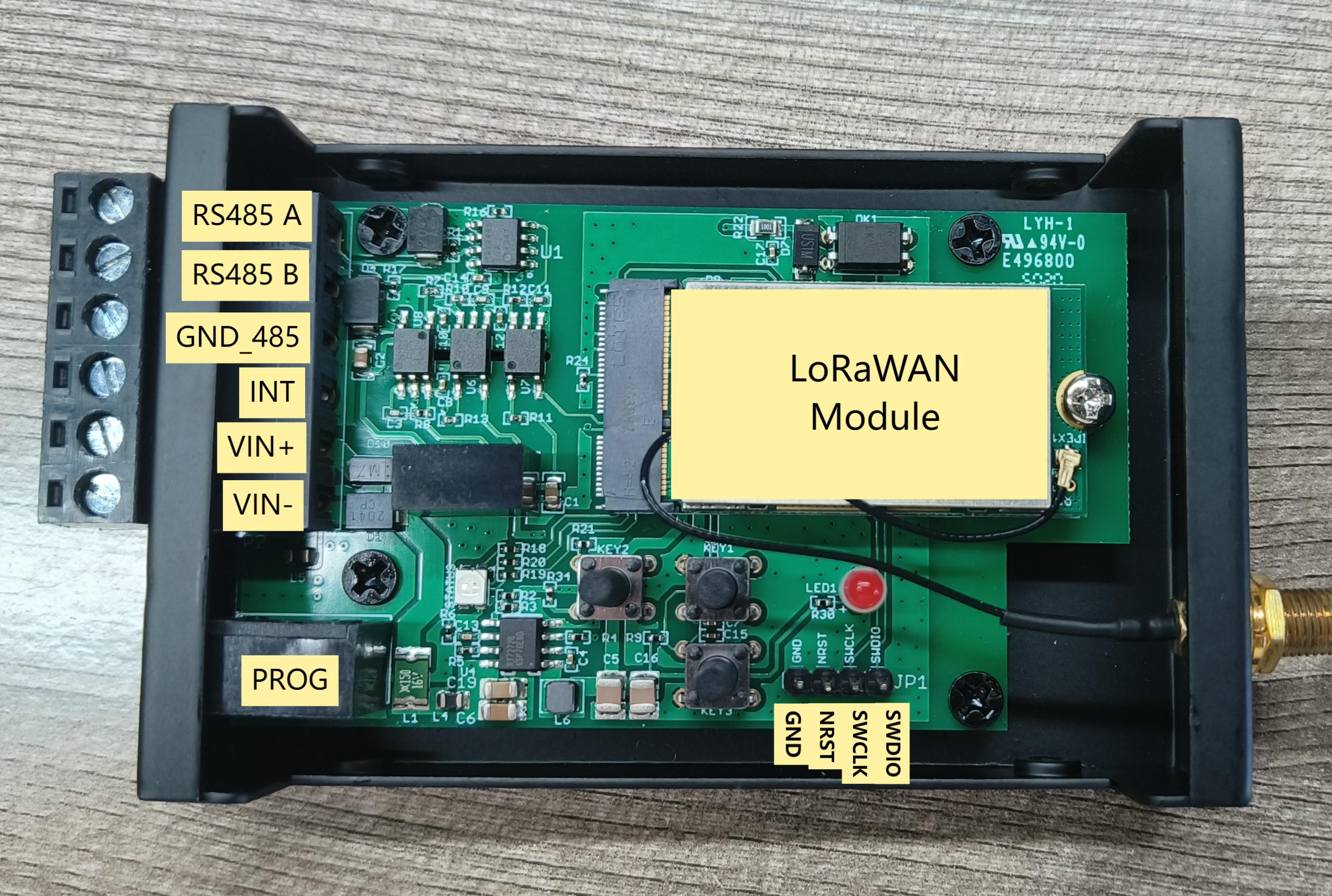
1.7 Pin Definitions
The following diagram shows the V1.2 hardware version.
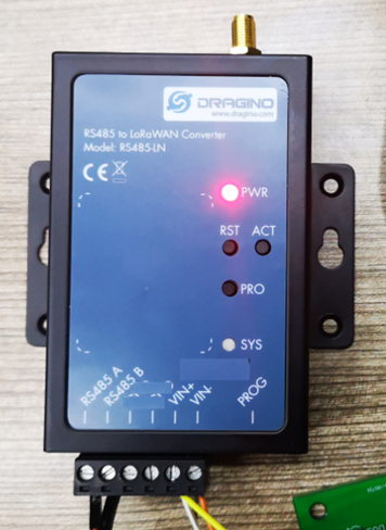
2. Power ON Device
The RS485-LN can be powered by 7 ~ 24V DC power source. Connection as below
- Power Source VIN to RS485-LN VIN+
- Power Source GND to RS485-LN VIN-
Once there is power, the RS485-LN will be on.
3. Operation Mode
3.1 How it works?
The RS485-LN is configured as LoRaWAN OTAA Class C mode by default. It has OTAA keys to join network. To connect a local LoRaWAN network, user just need to input the OTAA keys in the network server and power on the RS485-LN. It will auto join the network via OTAA.
3.2 Example to join LoRaWAN network
Here shows an example for how to join the TTN V3 Network. Below is the network structure, we use LG308 as LoRaWAN gateway here.
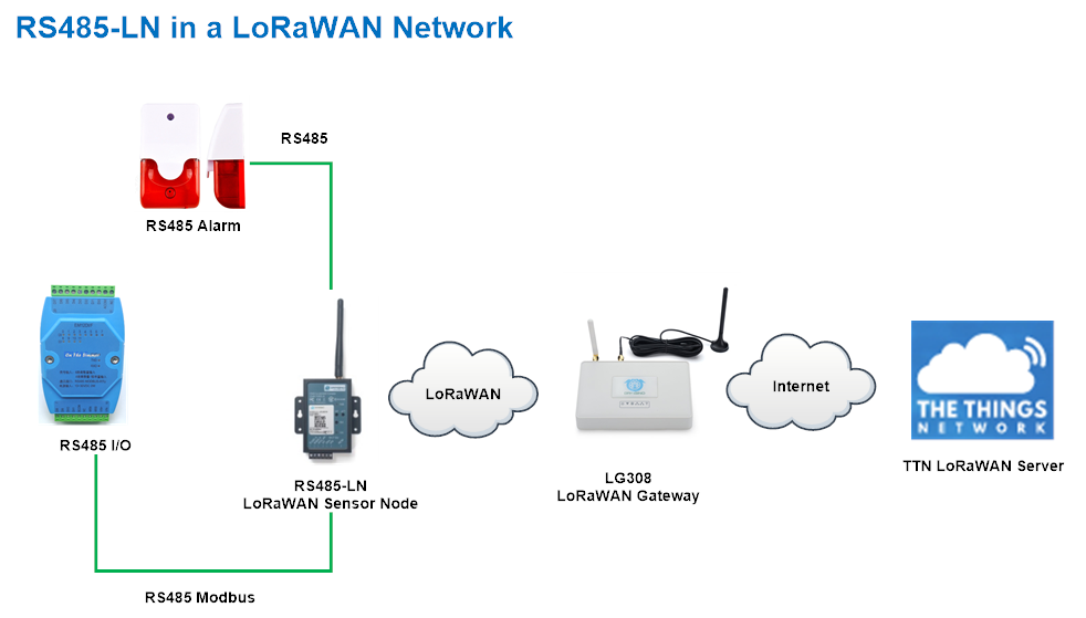
The RS485-LN in this example connected to two RS485 devices for demonstration, user can connect to other RS485 devices via the same method. The connection is as below:
485A+ and 485B- of the sensor are connected to RS485A and RA485B of RS485-LN respectively.
The LG308 is already set to connect to TTN V3 network . So what we need to now is only configure the TTN V3:
Step 1: Create a device in TTN V3 with the OTAA keys from RS485-LN.
Each RS485-LN is shipped with a sticker with unique device EUI:
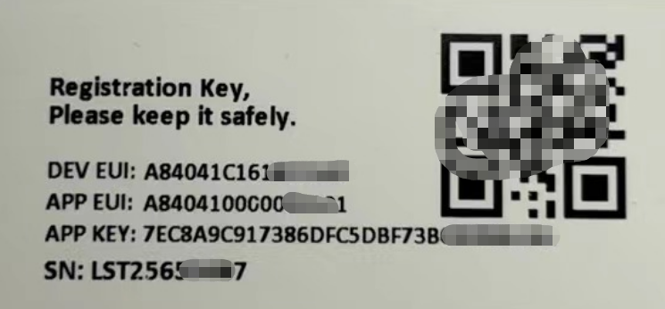

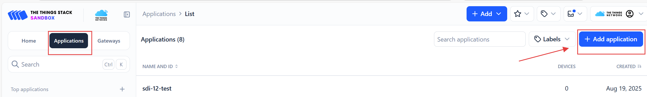
You can enter this key in the LoRaWAN Server portal. Below is TTN screen shot:
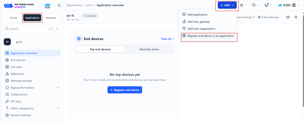
Create the application.
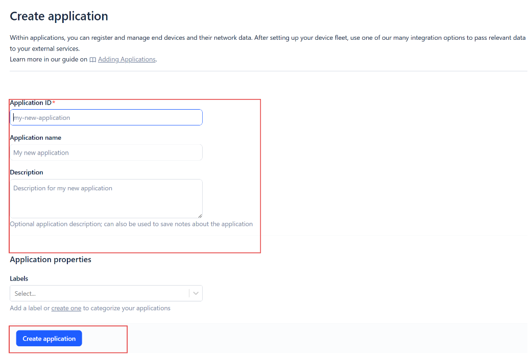
Add devices to the created Application.
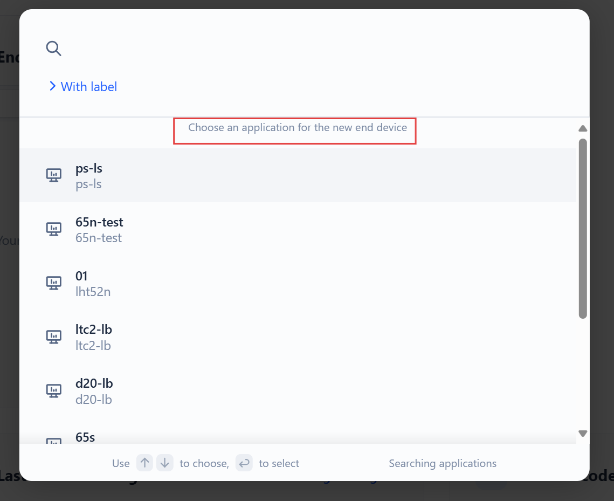
Enter end device specifics manually.
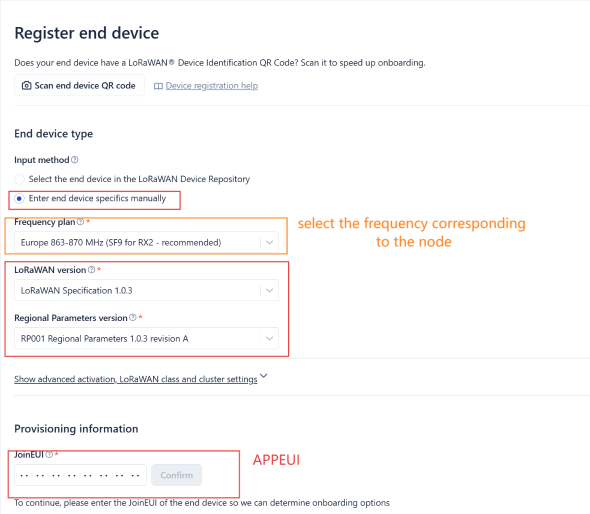
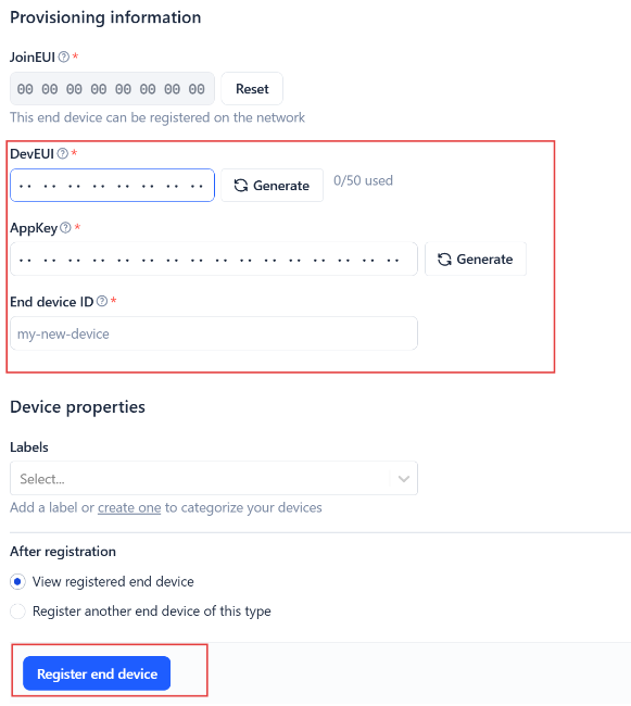
Add DevEUI and AppKey. Customize a platform ID for the device.
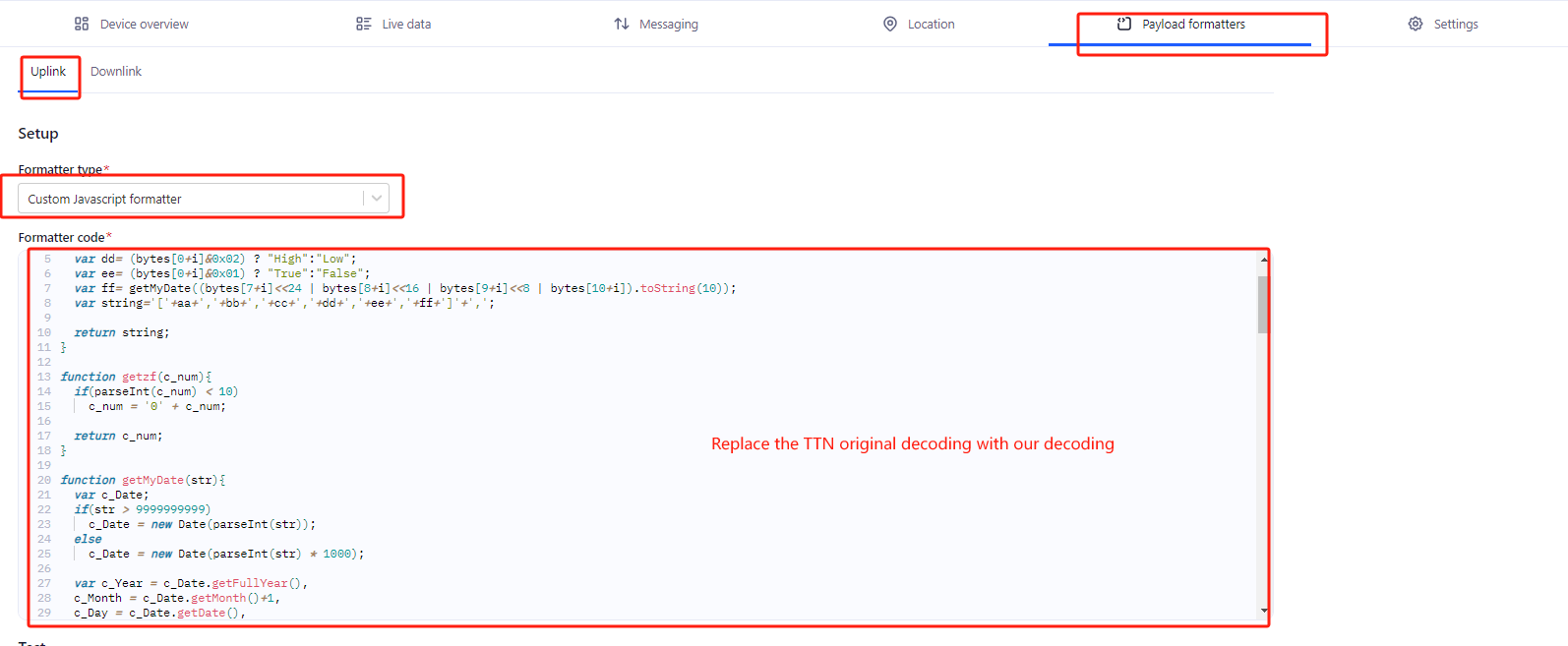
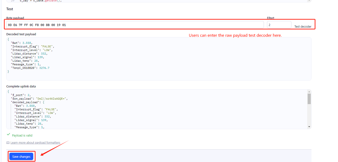
Step 2: Add decoder.
In TTN, user can add a custom payload so it shows friendly reading.
Click this link to get the decoder: https://github.com/dragino/dragino-end-node-decoder/tree/main/
Below is TTN screen shot:
Step 3: Activate on RS485-LN.
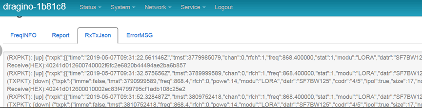
Press the button for 5 seconds to activate the RS485-LN. Power on RS485-BL and it will auto join to the TTN V3 network. After join success, it will start to upload message to TTN V3 and user can see in the panel.
3.3 Configure Device to Read RS485 Sensors
There are plenty of RS485 and TTL level devices in the market and each device has different commands to read the valid data. To support these devices in most flexible, RS485-LN supports flexible command set. User can use Dragino RS485 Tool, AT Commands or LoRaWAN Downlink Command to configure how RS485-LN should read the sensor and how to handle the return from RS485 or TTL sensors.
Note: below description and commands are for firmware version >v1.1, if you have firmware version v1.0. Please check the user manual v1.0 or upgrade the firmware to v1.1
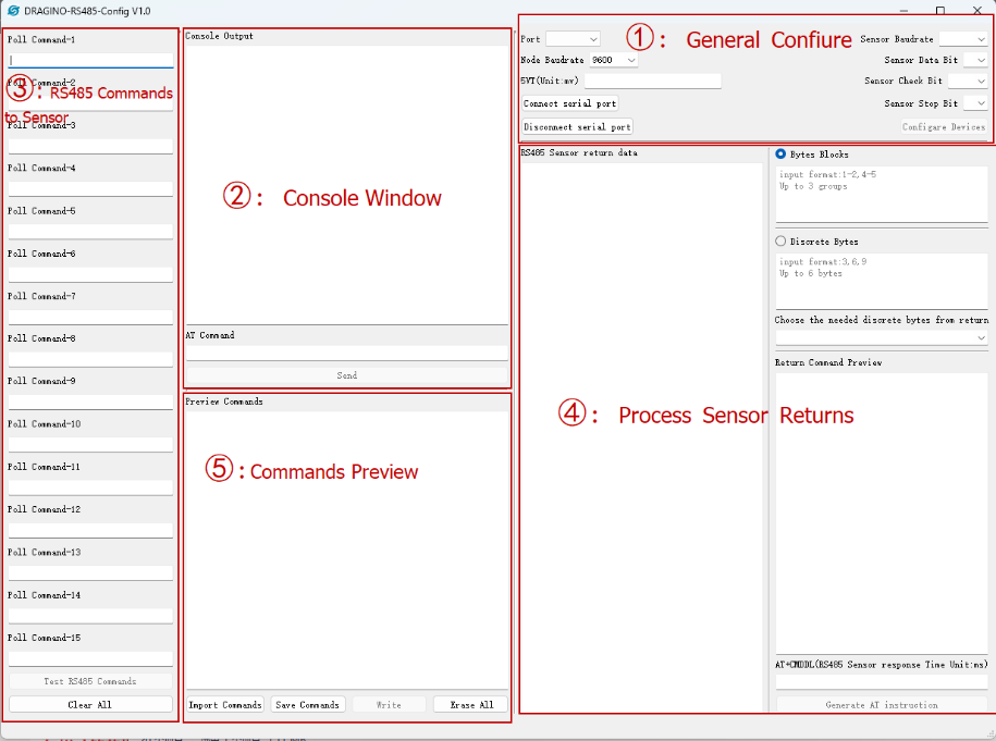
3.3.1 Method 1 -- via RS485 Configure Tool
Use the RS485 Configure tool is the recommand method. Please see the instruction of how to use the tool:
3.3.2 Method 2 -- via AT Commands
3.3.2.1 Configure UART settings for RS485 communication
To use RS485-LN to read data from RS485 sensors, connect the RS485-LN A/B traces to the sensors. The related commands for UART settings are:
| AT Commands | Description | Example |
|---|---|---|
| AT+BAUDR | Set the baud rate (for RS485 connection). Default Value is: 9600. | AT+BAUDR=9600 Options: (1200,2400,4800, 14400,19200,115200) |
| AT+PARITY | Set UART parity (for RS485 connection) | AT+PARITY=0 Option: 0: no parity, 1: odd parity, 2: even parity |
| AT+STOPBIT | Set serial stopbit (for RS485 connection) | AT+STOPBIT=0 for 1bit AT+STOPBIT=1 for 1.5 bit AT+STOPBIT=2 for 2 bits |
3.3.3 Configure sensors
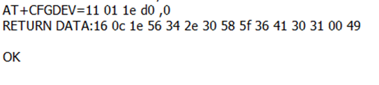
Some sensors might need to configure before normal operation. User can configure such sensor via PC and RS485 adapter or through RS485-LN AT Commands AT+CFGDEV. Each AT+CFGDEVequals to send a RS485 command to sensors. This command will only run when user input it and won't run during each sampling.
| AT Commands | Description | Example |
|---|---|---|
| AT+CFGDEV | This command is used to configure the RS485/TTL devices; they won’t be used during sampling. AT+CFGDEV=xx xx xx xx xx xx xx xx xx xx xx xx, mm: 0: no CRC, 1: add CRC-16/MODBUS in the end of this command | AT+CFGDEV=xx xx xx xx xx xx xx xx xx xx xx xx,m |
3.3.4 Configure read commands for each sampling
During each sampling, we need confirm what commands we need to send to the RS485 sensors to read data. After the RS485 sensors send back the value, it normally include some bytes and we only need a few from them for a shorten payload.
To save the LoRaWAN network bandwidth, we might need to read data from different sensors and combine their valid value into a short payload.
This section describes how to achieve above goals.
During each sampling, the RS485-LN can support 15 commands to read sensors. And combine the return to one or several uplink payloads.
Each RS485 commands include two parts:
1. What commands RS485-LN will send to the RS485 sensors. There are total 15 commands from AT+COMMAD1, ATCOMMAND2,…, to AT+COMMANDF. All commands are of same grammar.
2. How to get wanted value the from RS485 sensors returns from by 1). There are total 15 AT Commands to handle the return, commands are AT+DATACUT1,AT+DATACUT2,…, AT+DATACUTF corresponding to the commands from 1). All commands are of same grammar.
3. Some RS485 device might has longer delay on reply, so user can use AT+CMDDLto set the timeout for getting reply after the RS485 command is sent. For example AT+CMDDL1=1000 to send the open time to 1000ms
After we got the valid value from each RS485 commands, we need to combine them together with the command AT+DATAUP.
Below are examples for the how above AT Commands works.
AT+COMMANDx :This command will be sent to RS485 devices during each sampling, Max command length is 14 bytes. The grammar is:
| AT+COMMANDx=xx xx xx xx xx xx xx xx xx xx xx xx,m ** xx xx xx xx xx xx xx xx xx xx xx xx: The RS485 command to be sent ** m: 0: no CRC, 1: add CRC-16/MODBUS in the end of this command |
|---|
For example, if we have a RS485 sensor. The command to get sensor value is: 01 03 0B B8 00 02 46 0A. Where 01 03 0B B8 00 02 is the Modbus command to read the register 0B B8 where stored the sensor value. The 46 0A is the CRC-16/MODBUS which calculate manually.
In the RS485-LN, we should use this command AT+COMMAND1=0103 0B B8 00 02,1 for the same.
If a single command exceeds 14 bytes, you can use the command splicing function.
When AT+CMDDLx=1, the commands of AT+COMMANDx and AT+COMMAND(x+1) will be merged.
Examples: To send 00 01 02 03 04 05 06 07 08 09 0A 0B 0C 0D 0E 0F data it should be configured:
                `AT+COMMAND1=00` 01 02 03 04 05 06 07 08 09 0A 0B 0C 0D,0

                `AT+COMMAND1=1`

                `AT+COMMAND2=0E` 0F,0
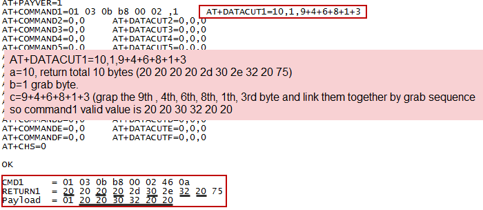
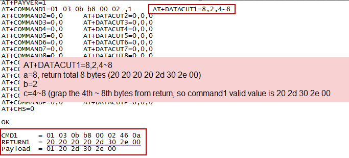
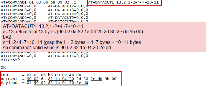
AT+DATACUTx :This command defines how to handle the return from AT+COMMANDx, max return length is 100 bytes.
AT+DATACUTx=a,b,c
|
|---|
Examples:
- Grab bytes
- Grab a section
- Grab different sections
3.3.5 Compose the uplink payload
Through AT+COMMANDx and AT+DATACUTx we got valid value from each RS485 commands, Assume these valid value are RETURN1, RETURN2, .., to RETURNx. The next step is how to compose the LoRa Uplink Payload by these RETURNs. The command is AT+DATAUP.
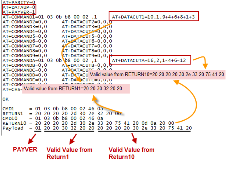
Examples: AT+DATAUP=0
Compose the uplink payload with value returns in sequence and send with A SIGNLE UPLINK.
Final Payload is Battery Info+PAYVER + VALID Value from RETURN1 + Valid Value from RETURN2 + … + RETURNx
Where PAYVER is defined by AT+PAYVER below is an example screen shot.
Examples: AT+DATAUP=1
Compose the uplink payload with value returns in sequence and send with Multiply UPLINKs.
Final Payload is PAYVER + PAYLOAD COUNT + PAYLOAD# + DATA
1. PAYVER: Defined by AT+PAYVER
2. PAYLOAD COUNT: Total how many uplinks of this sampling.
3. PAYLOAD#: Number of this uplink. (from 0,1,2,3…,to PAYLOAD COUNT)
4. DATA: Valid value: max 8 bytes for each uplink so each uplink <= 11 bytes. For the last uplink, DATA will might less than 8 bytes
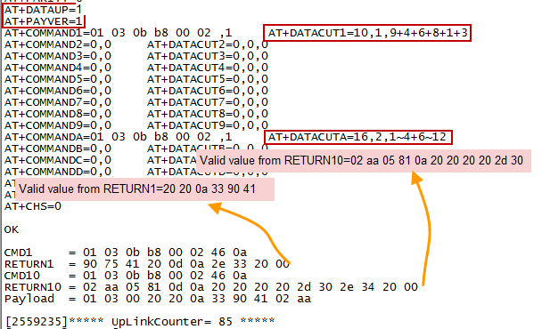
So totally there will be 3 uplinks for this sampling, each uplink include 8 bytes DATA
DATA1=RETURN1 Valid Value + the first two of Valid value of RETURN10= 20 20 0a 33 90 41 02 aa
DATA2=3rd ~ 10th byte of Valid value of RETURN10= 05 81 0a 20 20 20 20 2d
DATA3=the rest of Valid value of RETURN10= 30 Notice: In firmware v1.3, the Max bytes has been changed according to the max bytes in different Frequency Bands for lowest SF. As below:
* For AU915/AS923 bands, if UplinkDwell time=0, max 51 bytes for each uplink.
* For AU915/AS923 bands, if UplinkDwell time=0, max 11 bytes for each uplink.
* For US915 band, max 11 bytes for each uplink.
* For all other bands: max 51 bytes for each uplink.
** When AT+DATAUP=1,the maximum number of segments is 15, and the maximum total number of bytes is 1500; When AT+DATAUP=1and AT+ADR=0,the maximum number of bytes of each payload is determined by the DR value. (Since v1.4.0)**
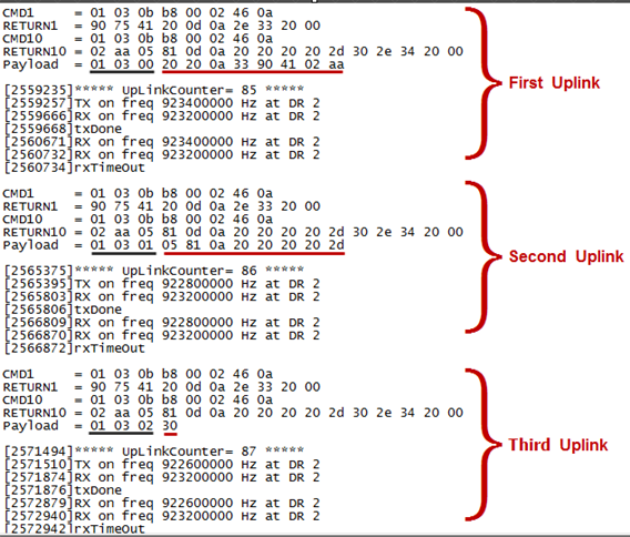
Below are the uplink payloads:
3.3.6 Uplink on demand
Except uplink periodically, RS485-LN is able to uplink on demand. The server send downlink command to RS485-LN and RS485 will uplink data base on the command.
Downlink control command: 0x08 command: Poll an uplink with current command set in RS485-LN.
** 0xA8 command**: Send a command to RS485-LN and uplink the output from sensors.
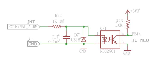
3.3.7 Uplink on Interrupt
RS485-LN support external Interrupt uplink since hardware v1.2 release.
3.3.7.1 Set Interrupt Mode
Before using the interrupt function of the INT pin, users can set the interrupt triggering mode as required.
AT command:
-
AT+INTMOD// Set the trigger interrupt mode -
AT+INTMOD=0// Disable Interrupt -
AT+INTMOD=1// Trigger by rising and falling edge -
AT+INTMOD=2// Trigger by falling edge (default) -
AT+INTMOD=3// Trigger by rising edge
Downlink Commands: 0x06
Format: Command Code (0x06) followed by 3 bytes.
Example1: Downlink Payload: 06 00 00 01// AT+INTMOD=1
Example2: Downlink Payload: 06 00 00 03//AT+INTMOD=3
3.3.7.2 Practical application
The following uses the default interrupt triggering mode (AT+INTMOD=2 as an example to show the interrupt function of INT:
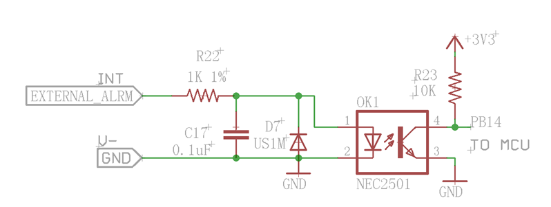
When a high voltage is given to the INT pin and then the level of the INT pin changes from high to low, the interrupt is triggered by a falling edge and the RS485-LN sends an uplink data.
Note: The level that triggers the interrupt ranges from 3.3V to 24V. Generally, it is recommended to use less than 12V. Example:
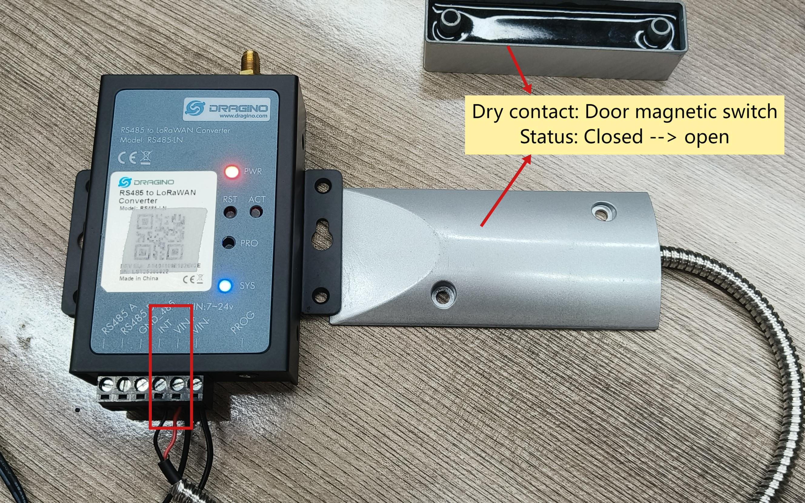
- Use a dry contact to connect the INT pin and VIN+ pin of the RS485-LN.
When the dry contact is closed, INT and VIN+ conduct and INT is high.
Disconnecting the dry contact, the level of the INT pin changes from high to low, triggering an interrupt (triggered along the falling edge), and the RS485-LN sends an uplink data.
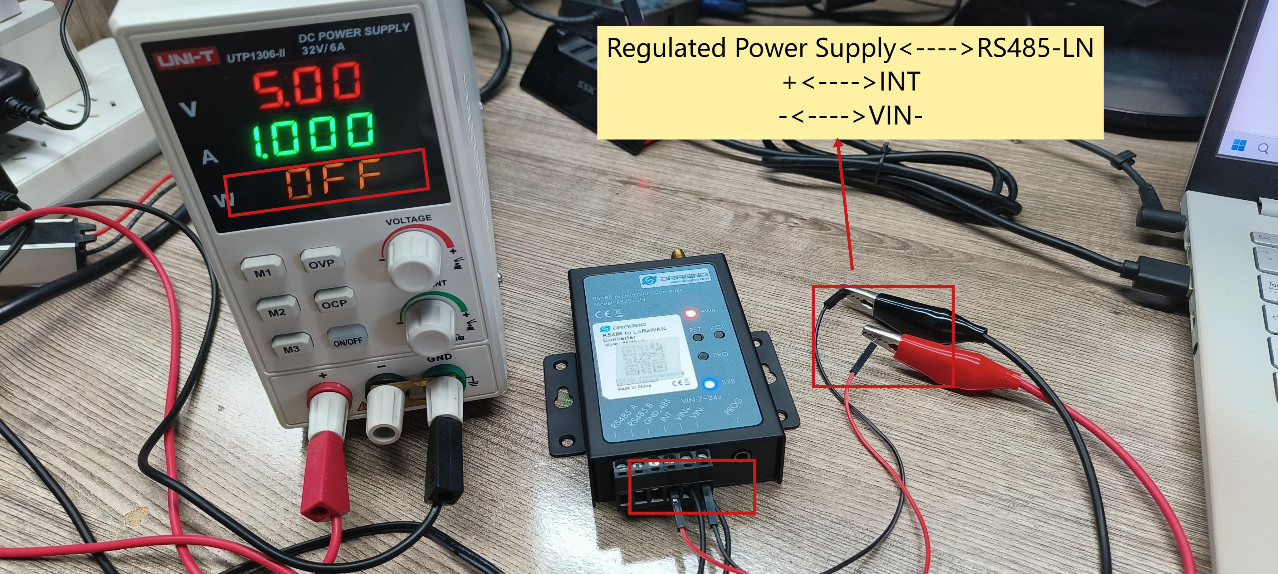
- Use a regulated power supply or a wet contact to connect the 485-LN to trigger the interruption.(This section uses a regulated power supply as an example.)
The positive pole of the stabilized power supply is connected to the INT pin of RS485-LN, and the negative pole of the stabilized power supply is connected to the VIN- pin of RS485-LN.
When the regulated power supply is operating, a high voltage is given to the INT pin and the INT level is high. When the regulated power supply is turned off, the level of the INT pin changes from
high to low, at which time an interrupt is triggered (triggered along the falling edge), and the device will send an uplink data.
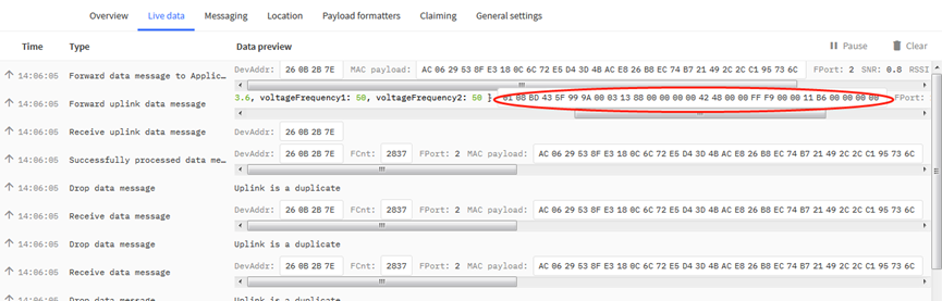
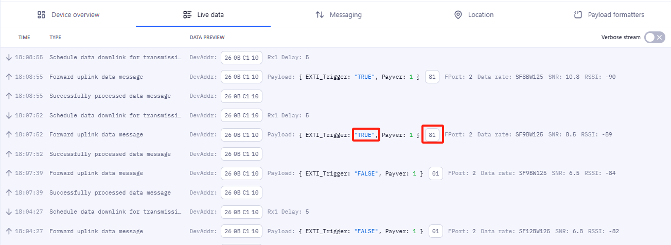
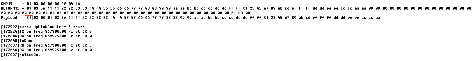
- Example of interrupt data in TTN.
The first byte of the payload of the interrupted packet is 0x81.
3.4 Uplink Payload
| Size(bytes) | 1 | Length depends on the return from the commands |
|---|---|---|
| Value | PAYLOAD_VER | If the valid payload is too long and exceed the maximum support payload length in server, server will show payload not provided in the LoRaWAN server. |
Below is the decoder for the first 3 bytes. The rest bytes are dynamic depends on different RS485 sensors.
3.5 Configure RS485-LN via AT or Downlink
User can configure RS485-LN via AT Commands or LoRaWAN Downlink Commands
There are two kinds of Commands:
Common Commands: They should be available for each sensor, such as: change uplink interval, reset device. For firmware v1.3, user can find what common commands it supports: AT Commands and Downlink Command
Sensor Related Commands: These commands are special designed for RS485-LN. User can see these commands below:
3.5.1 Common Commands
They should be available for each of Dragino Sensors, such as: change uplink interval, reset device. For firmware v1.3, user can find what common commands it supports: End Device AT Commands and Downlink Command
3.5.2 Downlink Response(Since firmware v1.4)
Response feature is added to the server's downlink, a special package with a FPort of 200 will be uploaded immediately after receiving the data sent by the server.
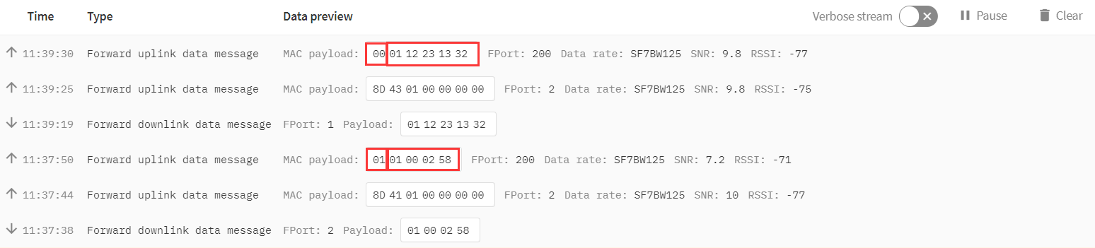
The first byte of this package represents whether the configuration is successful, 00 represents failure, 01 represents success. Except for the first byte, the other is the previous downlink. (All commands except A8 type commands are applicable)
3.5.3 Sensor related commands
RS485 Debug Command
This command is used to configure the RS485 devices; they won't be used during sampling. Max Length of AT+CFGDEVis 40 bytes.
-
AT Command
AT+CFGDEV=xxxx xx xx xx xx xx xx xx xx xx xx,m m: 0: no CRC, 1: add CRC-16/MODBUS in the end of this commandDownlink Payload
Format: ** A8 MM NN XX XX XX XX YY**
Where:
MM: 1: add CRC-16/MODBUS ; 0: no CRC
NN: The length of RS485 command
XX XX XX XX: RS485 command total NN bytes
YY: How many bytes will be uplink from the return of this RS485 command,
if YY=0, RS485-LN will execute the downlink command without uplink;
if YY\>0, RS485-LN will uplink total YY bytes from the output of this RS485 command; Fport=200
if YY=FF, RS485-LN will uplink RS485 output with the downlink command content; Fport=200.
Example 1: --> Configure without ask for uplink (YY=0)
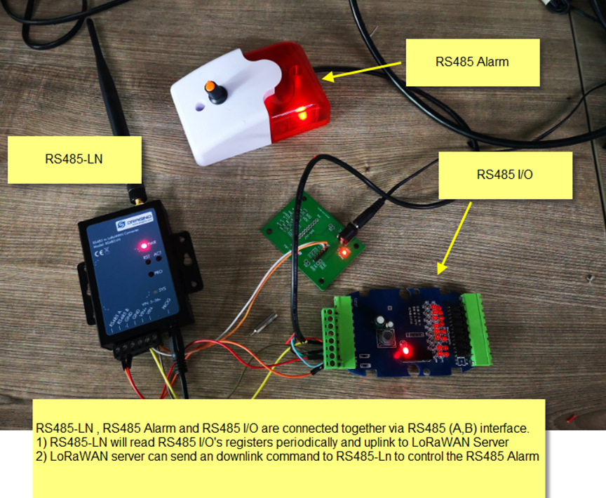
To connect a Modbus Alarm with below commands.
The command to active alarm is: 0A 05 00 04 00 01 4C B0. Where 0A 05 00 04 00 01 is the Modbus command to read the register 00 40 where stored the DI status. The 4C B0 is the CRC-16/MODBUS which calculate manually.
The command to deactivate alarm is: 0A 05 00 04 00 00 8D 70. Where 0A 05 00 04 00 00 is the Modbus command to read the register 00 40 where stored the DI status. The 8D 70 is the CRC-16/MODBUS which calculate manually.
So if user want to use downlink command to control to RS485 Alarm, he can use:
A8 01 06 0A 05 00 04 00 01 00: to activate the RS485 Alarm
A8 01 06 0A 05 00 04 00 00 00: to deactivate the RS485 Alarm
A8 is type code and 01 means add CRC-16/MODBUS at the end, the 3rd byte is 06, means the next 6 bytes are the command to be sent to the RS485 network, the final byte 00 means this command don’t need to acquire output.
Example 2:
Check TTL Sensor return:
Set Payload version
This is the first byte of the uplink payload. RS485-LN can connect to different sensors. User can set the PAYVER field to tell server how to decode the current payload.
-
**AT Command:
AT+PAYVER** Set PAYVER field = 1Downlink Payload: 0xAE 01 --> Set PAYVER field = 0x01
** 0xAE 0F** --> Set PAYVER field = 0x0F
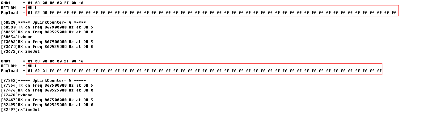
1 ) Add the interrupt flag at the highest bit of the Payver byte, that is, Byte7 of the first byte. (Since v1.4.0)
2 ) if the data intercepted by AT+DATACUTor AT+MBFUNis empty, it will display NULL, and the payload will be filled with n FFs.
Set RS485 Sampling Commands
AT+COMMANDx or AT+DATACUTx
These three commands are used to configure how the RS485-LN polling data from Modbus device. Detail of usage please see : polling RS485 device.
**AT Command: AT+COMMANDx: ** Configure RS485 read command to sensor.
** AT+DATACUTx: ** Configure how to handle return from RS485 devices.
Downlink Payload: 0xAF downlink command can be used to set AT+COMMANDx or AT+DATACUTx.
Note : if user use AT+COMMANDx to add a new command, he also need to send AT+DATACUTx downlink.
Format: ** AF MM NN LL XX XX XX XX YY**
Where:
MM: the ATCOMMANDor AT+DATACUTto be set. Value from 01 ~ 0F,
NN: 0: no CRC; 1: add CRC-16/MODBUS ; 2: set the AT+DATACUTvalue.
LL: The length of AT+COMMANDor AT+DATACUTcommand
XX XX XX XX: AT+COMMAND or AT+DATACUTcommand
YY: If YY=0, RS485-LN will execute the downlink command without uplink; if YY=1, RS485-LN will execute an uplink after got this command.
Example:
AF 03 01 06 0A 05 00 04 00 01 00: Same as AT+COMMAND3=0A05 00 04 00 01,1
AF 03 02 06 10 01 05 06 09 0A 00: Same as AT+DATACUT3=16,1,5+6+9+10
AF 03 02 06 0B 02 05 07 08 0A 00: Same as AT+DATACUT3=11,2,57+810
Fast command to handle MODBUS device AT+MBFUN is valid since v1.3 firmware version. The command is for fast configure to read Modbus devices. It is only valid for the devices which follow the MODBUS-RTU protocol.
This command is valid since v1.3 firmware version
AT+MBFUNcan auto read the Modbus function code: 01, 02, 03 or 04. AT+MBFUN has lower priority vs AT+DATACUTcommand. If AT+DATACUTcommand is configured, AT+MBFUN will be ignore.
Example:
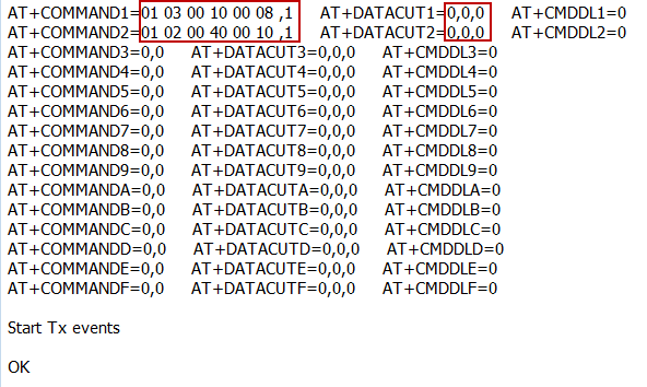
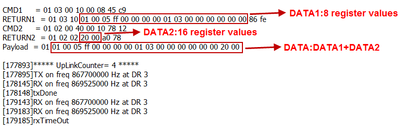
AT+MBFUN=1 and AT+DATACUT1``AT+DATACUT2 are not configure (0,0,0). So RS485-LN.
AT+COMMAND1=01 03 00 10 00 08,1 --> read slave address 01 , function code 03, start address 00 01, quantity of registers 00 08.
AT+COMMAND2=01 02 00 40 00 10,1 --> read slave address 01 , function code 02, start address 00 40, quantity of inputs 00 10.
Downlink Command: A9 aa --> Same as AT+MBFUN=aa
RS485 command timeout
Some Modbus device has slow action to send replies. This command is used to configure the RS485-LN to use longer time to wait for their action.
Default value: 0, range: 0 ~ 65 seconds
-
** AT Command: AT+CMDDLaa=hex(bb cc)*1000 Example: AT+CMDDL1=1000** to send the open time to 1000ms
** Downlink Payload: 0x AA aa bb cc** Same as: AT+CMDDLaa=hex (bb cc)
Example: 0xAA 01 03 E8 --> Same as AT+CMDDL1=1000 ms
Uplink payload mode
Define to use one uplink or multiple uplinks for the sampling.
The use of this command please see: Compose Uplink payload
- ** AT Command: AT+DATAUP=0 AT+DATAUP=1 0xAD 01 00 00 14 -->** Same as
AT+DATAUP=1,20000// (00 00 14 is 20 seconds)
Each uplink is sent to the server at 20-second intervals when segmented.
** Downlink Payload: 0xAD 00 -->** Same as AT+DATAUP=0
** 0xAD 01 -->** Same as AT+DATAUP=1 //Each uplink is sent to the server one after the other as it is segmented.
(Since firmware v1.4.0)
** AT Command: AT+DATAUP=1Timeout Downlink Payload: 0xAD 01 00 00 14 -->** Same as AT+DATAUP=1,20000 // (00 00 14 is 20 seconds)
Each uplink is sent to the server at 20-second intervals when segmented.
Cut data separation processing(Since Version 1.4.2)
AT+NEWLINEcommand, which only takes effect when AT+DATAUP=1or AT+DATAUP=1,timeout.
When not set, each part of AT+DATAUPis sent according to the maximum number of bytes of DR.
When setting, each part of AT+DATAUPis sent according to the value set by AT+NEWLINE
** AT Command:**
*AT+NEWLINE=ALL *The data cut out by each AT+COMMANDx command is sent separately as an uplink.
AT+NEWLINE=ALL equal: AT+NEWLINE=1+2+3+4+5+6+7+8+9+10+11+12+13+14+15
*AT+NEWLINE=a+b+c *The data returned by all commands is divided into three parts, COMMAND(1a) is the first part, COMMAND(a+1b) is the second part,COMMAND(b+1~c) is the third part.
*AT+NEWLINE=NULL *Turn off the functionality of this AT command.
** Downlink Payload:**
AT+NEWLINE=ALL ---> 0xAC 01
AT+NEWLINE=NULL ---> 0xAC 00*
AT+NEWLINE= a+b+c ---> 0xAC number of bytes a b c
AT+NEWLINE= 1+5+15 ---> 0xAC 03 01 05 0F
Manually trigger an Uplink
Ask device to send an uplink immediately.
** AT Command:**
No AT Command for this, user can press the ACT button for 1 second for the same.
** Downlink Payload: 0x08 FF**, RS485-LN will immediately send an uplink.
Clear RS485 Command
The AT+COMMANDx and AT+DATACUTx settings are stored in special location, user can use below command to clear them.
** AT Command: AT+CMDEAR=mmnn** mm: start position of erase ,nn: stop position of erase
Etc. AT+CMDEAR=1,10 means erase AT+COMMAND1``AT+DATACUT1to AT+COMMAND10``AT+DATACUT10
Example screen shot after clear all RS485 commands.
The uplink screen shot is:

** Downlink Payload: 0x09 aa bb** same as AT+CMDEAR=aa,bb
Set Serial Communication Parameters
Set the Rs485 serial communication parameters:
AT Command:
- Set Baud Rate
** AT+BAUDR=9600** // Options: (200~115200) When using low baud rate or receiving multiple bytes, you need to use AT+CMDDLto increase the receive timeout (the default receive timeout is 400ms), otherwise data will be lost
- Set UART Parity
** AT+PARITY=0** // Option: 0: no parity, 1: odd parity, 2: even parity
- Set STOPBIT
** AT+STOPBIT=0** // Option: 0 for 1bit; 1 for 1.5 bit ; 2 for 2 bits
Downlink Payload: A7 01 aa bb: Same AT+BAUDR=hex(aa bb)*100
Example:
A7 01 00 60 same as AT+BAUDR=9600
A7 01 04 80 same as AT+BAUDR=115200
-
A7 02 aa: Same as
AT+PARITY=aa(aa value: 00 , 01 or 02) -
A7 03 aa: Same as
AT+STOPBIT=aa(aa value: 00 , 01 or 02)
**Configure Databit (Since Version 1.4.0) AT Command: AT+DATABIT=7 **// Set the data bits to 7
** AT+DATABIT=8 **// Set the data bits to 8
Downlink Payload: A7 04 07: Same as AT+DATABIT=7
** A7 04 08**: Same as AT+DATABIT=8
**Encrypted payload(Since Version 1.4.0) AT Command: AT+DECRYPT=1 ** // The payload is uploaded without encryption
** AT+DECRYPT=0 ** // Encrypt when uploading payload (default)
**Get sensor value(Since Version 1.4.0) AT Command: AT+GETSENSORVALUE=0 ** // The serial port gets the reading of the current sensor
** AT+GETSENSORVALUE=1 ** // The serial port gets the current sensor reading and uploads it.
**Resets the downlink packet count(Since Version 1.4.0) AT Command: AT+DISFCNTCHECK=0 ** // When the downlink packet count sent by the server is less than the node downlink packet count or exceeds 16384, the node will no longer receive downlink packets (default)
** AT+DISFCNTCHECK=1 ** // When the downlink packet count sent by the server is less than the node downlink packet count or exceeds 16384, the node resets the downlink packet count and keeps it consistent with the server downlink packet count.
When the limit bytes are exceeded, upload in batches(Since Version 1.4.0) AT Command: AT+DISMACANS=0 // When the MACANS of the reply server plus the payload exceeds the maximum number of bytes of 11 bytes (DR0 of US915, DR2 of AS923, DR2 of AU195), the node will send a packet with a payload of 00 and a port of 4. (default)
** AT+DISMACANS=1** // When the MACANS of the reply server plus the payload exceeds the maximum number of bytes of the DR, the node will ignore the MACANS and not reply, and only upload the payload part.
** Downlink Payload: 0x21 00 01 ** // Set the DISMACANS=1
Copy downlink to uplink (Since Version 1.4.0) AT Command: AT+RPL=5 // After receiving the package from the server, it will immediately upload the content of the package to the server, the port number is 100.
Example:aa xx xx xx xx // aa indicates whether the configuration has changed, 00 is yes, 01 is no; xx xx xx xx are the bytes sent.
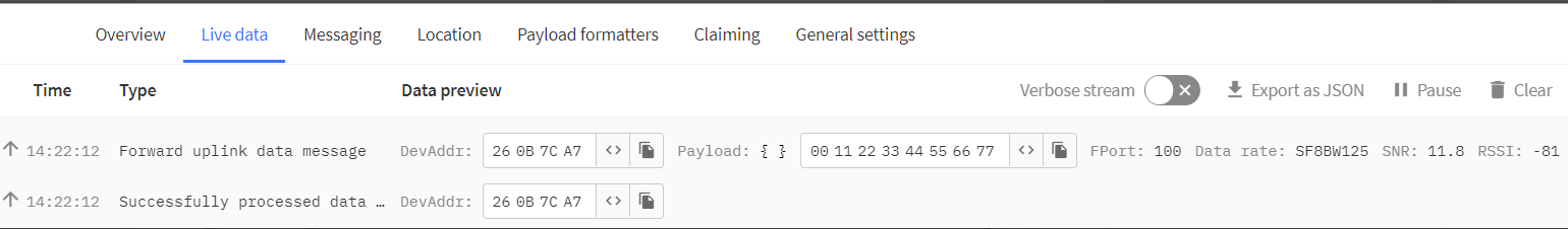
For example, sending 11 22 33 44 55 66 77 will return invalid configuration 00 11 22 33 44 55 66 77.
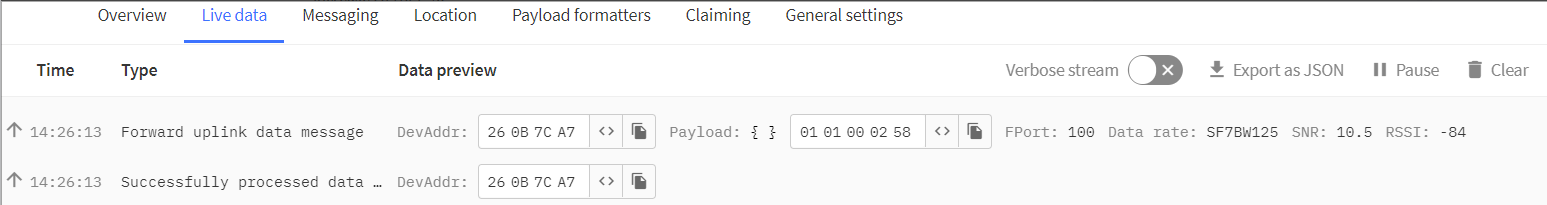
For example, if 01 00 02 58 is issued, a valid configuration of 01 01 00 02 58 will be returned.
Query version number and frequency band 、TDC(Since Version 1.4.0)
- **Downlink Payload: 26 01 ** // Downlink 26 01 can query device upload frequency, frequency band, software version number, TDC time.
Example:

** Monitor RS485 communication of other devices(Since Version 1.4.0) AT Command:**
AT+RXMODE=1,10 // When the RS485-LN receives more than 10 bytes from the RS485, it immediately sends the uplink of the received data.
AT+RXMODE=2,500// RS485-LN uploads data as uplink from the first byte received by RS485 to the data received within 500ms after that.
AT+RXMODE=0,0// Disable this mode (default)
**Downlink Payload: A6 aa bb bb ** // same as AT+RXMODE=aa,bb
3.6 Listening mode for RS485 network
This feature support since firmware v1.4
RS485-LN supports listening mode, it can listen the RS485 network packets and send them via LoRaWAN uplink. Below is the structure. The blue arrow shows the RS485 network packets to RS485-LN.
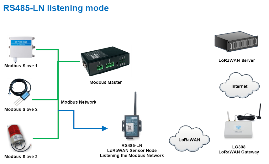
To enable the listening mode, use can run the command ** AT+RXMODE**.
| Command example | Function |
|---|---|
| AT+RXMODE=1,10 | Enable listening mode 1, if RS485-LN has received more than 10 RS485 commands from the network. RS485-LN will send these commands via LoRaWAN uplinks. |
| AT+RXMODE=2,500 | Enable listening mode 2, RS485-LN will capture and send a 500ms content once from the first detect of character. Max value is 65535 ms |
| AT+RXMODE=0,0 | Disable listening mode. This is the default settings. |
| A6 aa bb cc same as AT+RXMODE=aa,(bb<<8 | cc) |
**Downlink Command: 0xA6 aa bb cc ** same as AT+RXMODE=aa,(bb\<<8| cc)
Example:
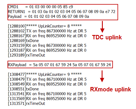
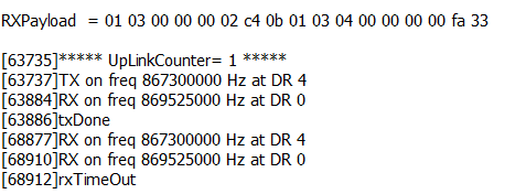
The RS485-LN is set to AT+RXMODE=2,1000
There is a two Modbus commands in the RS485 network as below:
The Modbus master send a command: 01 03 00 00 00 02 c4 0b
And Modbus slave reply with: 01 03 04 00 00 00 00 fa 33
RS485-LN will capture both and send the uplink: 01 03 00 00 00 02 c4 0b 01 03 04 00 00 00 00 fa 33
Notice: Listening mode can work with the default polling mode of RS485-LN. When RS485-LN is in to send the RS485 commands (from AT+COMMANDx), the listening mode will be interrupt for a while.
3.7 Buttons
| Button | Feature |
|---|---|
| ACT | If RS485 joined in network, press this button for more than 1 second, RS485 will upload a packet, and the SYS LED will give a Blue blink |
| RST | Reboot RS485 |
| PRO | Use for upload image, see How to Update Image |
3.8 LEDs
| LEDs | Feature |
|---|---|
| PWR | Always on if there is power |
| SYS | After device is powered on, the SYS will fast blink in GREEN for 5 times, means RS485-LN start to join LoRaWAN network. If join success, SYS will be **on GREEN for 5 seconds . **SYS will blink Blue on every upload and blink Green once receive a downlink message. |
4. Case Study
User can check this URL for some case studies: APP RS485 COMMUNICATE WITH SENSORS
5. Use AT Command
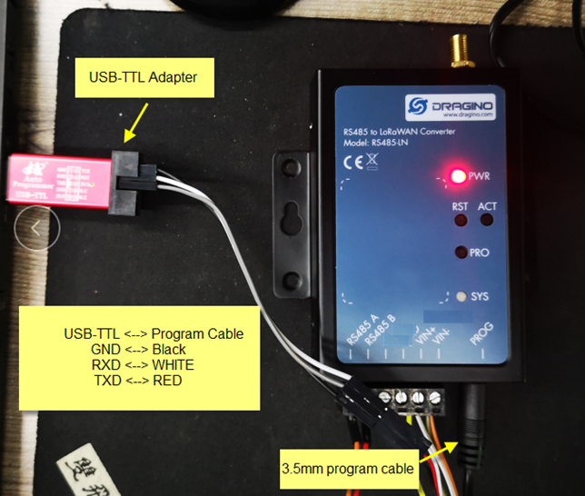
5.1 Access AT Command
RS485-LN supports AT Command set. User can use a USB to TTL adapter plus the 3.5mm Program Cable to connect to RS485-LN to use AT command, as below.
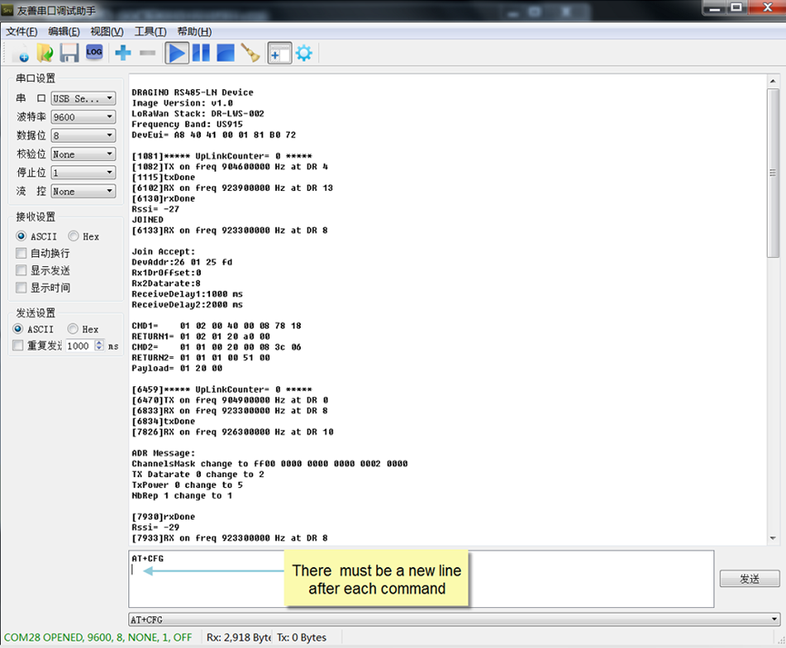
In PC, User needs to set serial tool(such as putty, SecureCRT) baud rate to 9600 to access to access serial console of RS485-LN. The default password is 123456. Below is the output for reference:
More detail AT Command manual can be found at AT Command Manual
5.2 Common AT Command Sequence
5.2.1 Multi-channel ABP mode (Use with SX1301/LG308)
If device has not joined network yet:
-
AT+FDR -
AT+NJM=0 -
ATZIf device already joined network: -
AT+NJM=0 -
ATZ
5.5.2 Single-channel ABP mode (Use with LG01/LG02)
AT+FDR Reset Parameters to Factory Default, Keys Reserve
AT+NJM=0Set to ABP mode
AT+ADR=0 Set the Adaptive Data Rate Off
AT+DR=5 Set Data Rate
AT+TDC=60000 Set transmit interval to 60 seconds
AT+CHS=868400000 Set transmit frequency to 868.4Mhz
AT+RX2FQ=868400000 Set RX2Frequency to 868.4Mhz (according to the result from server)
AT+RX2DR=5 Set RX2DR to match the downlink DR from server. see below
AT+DADDR=26 01 1A F1 Set Device Address to 26 01 1A F1, this ID can be found in the LoRa Server portal.
ATZReset MCU
Note:
- Make sure the device is set to ABP mode in the IoT Server.
- Make sure the LG01/02 gateway RX frequency is exactly the same as
AT+CHSsetting. - Make sure SF / bandwidth setting in LG01/LG02 match the settings of
AT+DRrefer this link to see what DR means. - The command
AT+RX2FQandAT+RX2DRis to let downlink work. to set the correct parameters, user can check the actually downlink parameters to be used. As below. Which shows the RX2FQ should use 868400000 and RX2DR should be 5
6. FAQ
6.1 How to upgrade the image?
The RS485-LN LoRaWAN Controller is shipped with a 3.5mm cable, the cable is used to upload image to RS485-LN to:
Support new features
For bug fix
Change LoRaWAN bands.
Below shows the hardware connection for how to upload an image to RS485-LN:

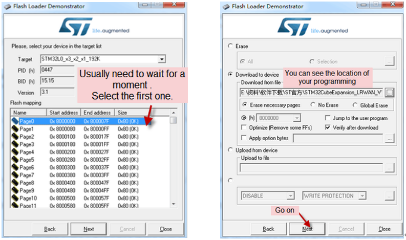
Step1: Download flash loader.
Step2: Download the LT Image files.
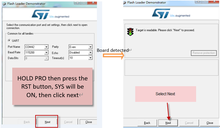
**Step3: **Open flashloader; choose the correct COM port to update.
Hold down the PRO button and then momentarily press the RST reset button and the SYS led will change from OFF to ON, While SYS LED is RED ON, it means the RS485-LN is ready to be program.
Users can select the new burning software STM32Cubeprogramer for firmware upgrade and follow the same connection steps to enter burning mode (until SYS LED is RED ON):
http:///docs/wiki/Configuration/end-node/stm32-firmware-upgrade/
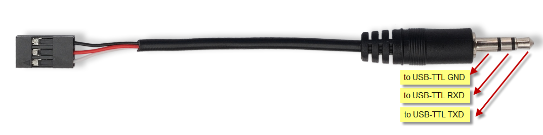
Notice: In case user has lost the program cable. User can hand made one from a 3.5mm cable. The pin mapping is:
6.2 How to change the LoRa Frequency Bands/Region?
User can follow the introduction for how to upgrade image. When download the images, choose the required image file for download.
6.3 How many RS485-Slave can RS485-LN connects?
The RS485-LN can support max 32 RS485 devices. Each uplink command of RS485-LN can support max 15 different RS485 command. So RS485-LN can support max 15 RS485 devices pre-program in the device for uplink. For other devices no pre-program, user can use the downlink message (type code 0xA8) to poll their info.
6.4 Compatible question to ChirpStack and TTI LoRaWAN server ?
When user need to use with ChirpStack or TTI. Please set AT+RPL=4.
Detail info check this link: Set Packet Receiving Response Level
6.5 Can i use point to point communication for RS485-LN?
Yes, please updating point-to-point firmware,then refer Point to Point Communication for RS485-LN.
6.6 How to Use RS485-LN to connect to RS232 devices?
Use RS485-BL or RS485-LN to connect to RS232 devices. - DRAGINO
6.7 How to judge whether there is a problem with the set COMMAND
6.7.1 Introduce:
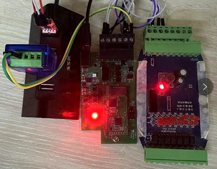
Users can use below the structure to fast debug the communication between RS485BL and RS485-LN. The principle is to put the PC in the RS485 network and sniff the packet between Modbus MTU and RS485-BL/LN. We can use this way to:
- Test if Modbus-MTU works with PC commands.
- Check if RS485-LN sent the expected command to Mobus-MTU
- Check if Modbus-MTU return back the expected result to RS485-LN.
- If both b) and c) has issue, we can compare PC’s output and RS485-LN output.
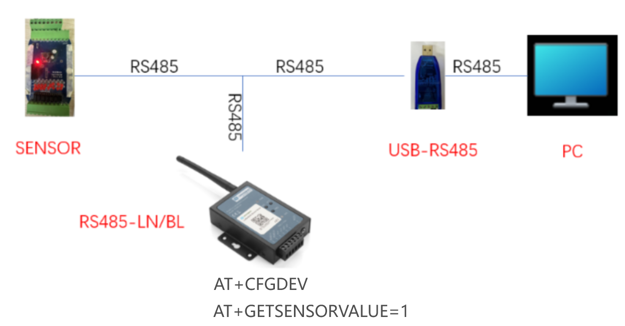
Example Connection:

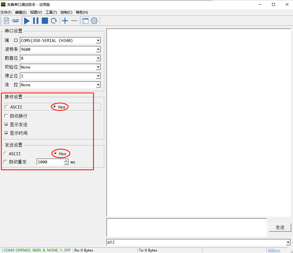
6.7.2 Set up PC to monitor RS485 network With Serial tool
Note: Receive and send set to hex mode
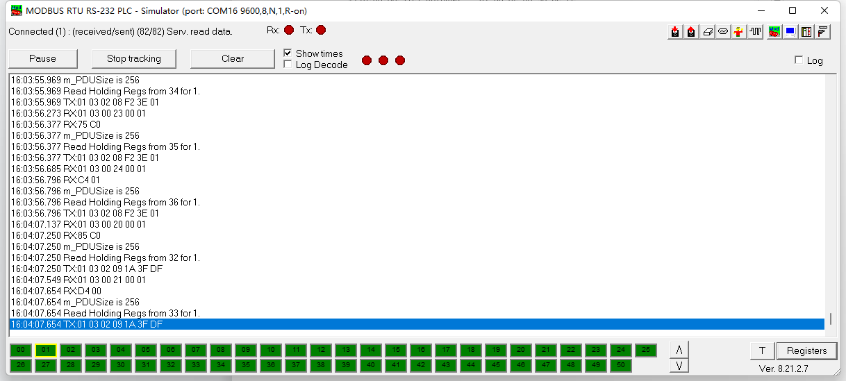
6.7.3 With ModRSsim2:
(1) Select serial port MODBUS RS-232
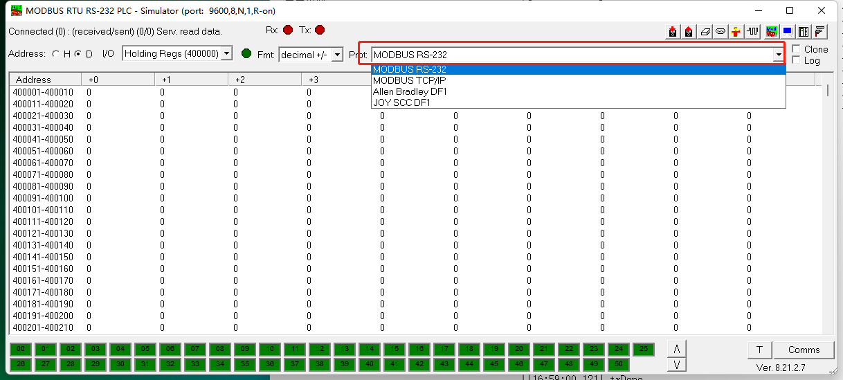
(2) Click the serial port icon
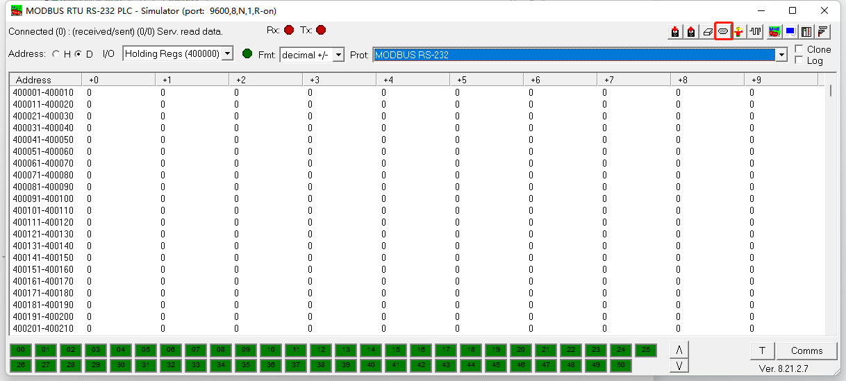
(3) After selecting the correct serial port and baud rate, click ok
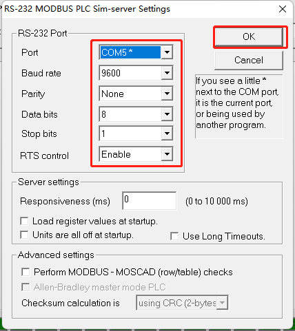
(4) Click the comms.
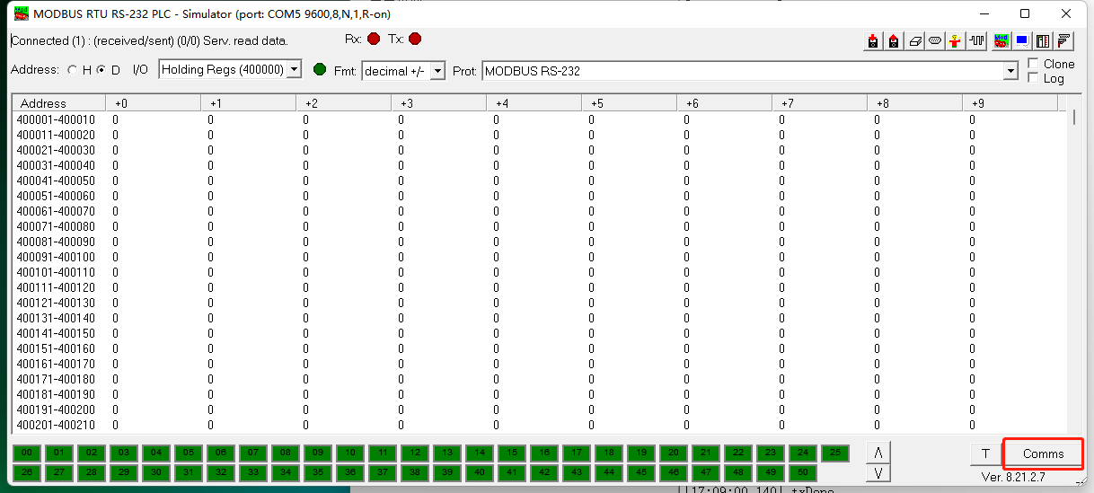
Run RS485-LN/BL command and monitor if it is correct.
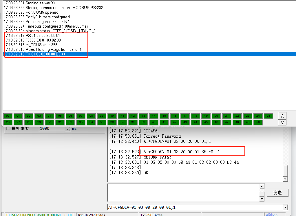
6.7.4 Example – Test the CFGDEV command
RS485-LN sent below command:
AT+CFGDEV=01 03 00 20 00 01,1to RS485 network, and PC is able to get this command and return commands from MTU to show in the serial tool.
We can see the output from the Serial port tool to analyze. And check if they are expected result.
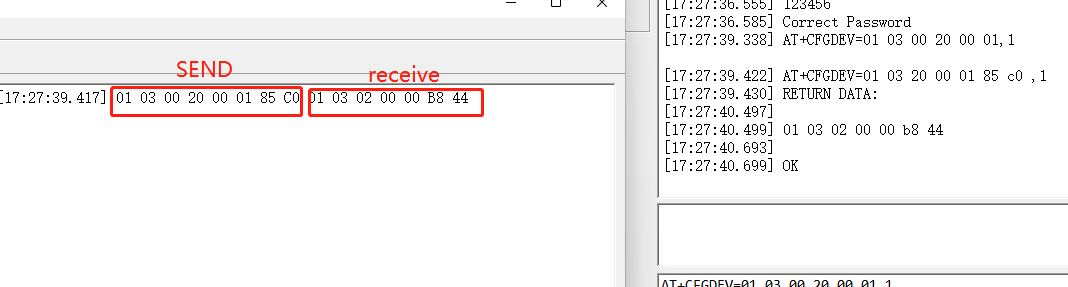
We can also use ModRSsim2 to see the output.
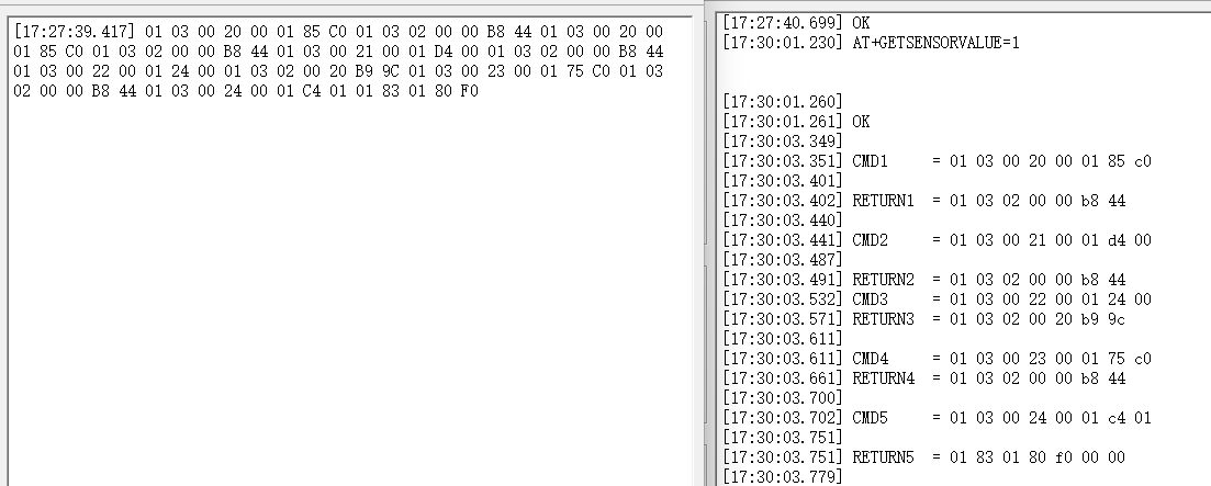
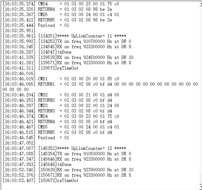
6.7.5 Example – Test CMD command sets.
Run AT+GETSENSORVALUE=1 to test the CMD commands set in RS485-LN.
Serial port tool:
ModRSsim2:
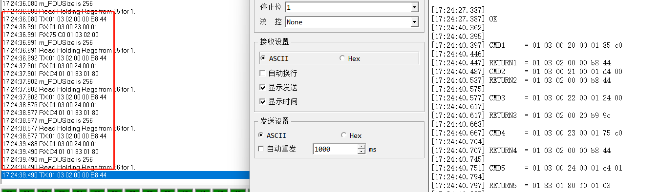
6.7.6 Test with PC
If there is still have problem to set up correctly the commands between RS485-LN and MTU. User can test the correct RS485 command set in PC and compare with the RS485 command sent out via RS485-LN. as long as both commands are the same, the MTU should return correct result.
Or User can send the working commands set in PC serial tool to Dragino Support to check what should be configured in RS485-LN.
Connection method:
Link situation:
6.8 Where to get the decoder for RS485-LN?
The decoder for RS485-LN needs to be written by yourself. Because the sensor to which the user is connected is custom, the read device data bytes also need custom parsing, so there is no universal decoder. We can only provide templates for decoders (no intermediate data parsing part involved)
6.9 How to configure RS485 commands more conveniently?
Dragino has developed an application for the RS485 series of products.
It can help you configure RS485 sensors more conveniently Please refer to the link below for specific usage:
RS485 Configure Tool - DRAGINO
6.10 How to determine whether the returned data value FF is valid data or invalid data?
The address of the returned data can be used as a flag.
The customer uses the intercept command to intercept the first bit of the returned data (the slave address of the sensor) as a judgment flag.
Invalid data:
If the first bit and the data are both FF, it means the data is empty.
Valid data: If the first bit is a normal slave address and the data is FF, it means the data is normal.
7. Trouble Shooting
7.1 Downlink doesn't work, how to solve it?
Please see this link for debug: LoRaWAN Communication Debug
7.2 Why customers can't join TTN V3 in US915 /AU915 bands?
It might about the channels mapping. Please see for detail: Notice of Frequency band
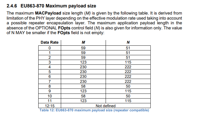
7.3 Why can't customers see the device's data in the server when the data is too long?
This is due to the limitation of the lorawan protocol, and the fixed DR needs to be adjusted to improve this problem.
Please refer to the following link for the number of bytes limited by different frequencies and different DRs in the lorawan protocol
lora-alliance.org/wp-content/uploads/2021/05/RP002-1.0.3-FINAL-1.pdf
Example:
Please refer to the following command to fix DR
AT+ADR=0
AT+DR=3
Downlink command:
http:///docs/wiki/Configuration/end-node/at-commands-downlink/
8. Order Info
Part Number: RS485-LN-XXX XXX:
- EU433: frequency bands EU433
- EU868: frequency bands EU868
- KR920: frequency bands KR920
- CN470: frequency bands CN470
- AS923: frequency bands AS923
- AU915: frequency bands AU915
- US915: frequency bands US915
- IN865: frequency bands IN865
- RU864: frequency bands RU864
- KZ865: frequency bands KZ865
9. Packing Info
Package Includes:
- RS485-LN x 1
- Stick Antenna for LoRa RF part x 1
- Program cable x 1
Dimension and weight:
- Device Size: 13.5 x 7 x 3 cm
- Device Weight: 105g
- Package Size / pcs : 14.5 x 8 x 5 cm
- Weight / pcs : 170g
10. FCC Caution for RS485LN-US915
Any Changes or modifications not expressly approved by the party responsible for compliance could void the user's authority to operate the equipment.
This device complies with part 15 of the FCC Rules. Operation is subject to the following two conditions: (1) This device may not cause harmful interference, and (2) this device must accept any interference received, including interference that may cause undesired operation.
**IMPORTANT NOTE: Note: **This equipment has been tested and found to comply with the limits for a Class B digital device, pursuant to part 15 of the FCC Rules. These limits are designed to provide reasonable protection against harmful interference in a residential installation. This equipment generates, uses and can radiate radio frequency energy and, if not installed and used in accordance with the instructions, may cause harmful interference to radio communications. However, there is no guarantee that interference will not occur in a particular installation. If this equipment does cause harmful interference to radio or television reception, which can be determined by turning the equipment off and on, the user is encouraged to try to correct the interference by one or more of the following measures:
—Reorient or relocate the receiving antenna.
—Increase the separation between the equipment and receiver.
—Connect the equipment into an outlet on a circuit different from that to which the receiver is connected.
—Consult the dealer or an experienced radio/TV technician for help.
FCC Radiation Exposure Statement:
This equipment complies with FCC radiation exposure limits set forth for an uncontrolled environment.This equipment should be installed and operated with minimum distance 20cm between the radiator& your body.
11. Support
Support is provided Monday to Friday, from 09:00 to 18:00 GMT+8. Due to different timezones we cannot offer live support. However, your questions will be answered as soon as possible in the before-mentioned schedule.
Provide as much information as possible regarding your enquiry (product models, accurately describe your problem and steps to replicate it etc) and send a mail to support@dragino.com.
0
Point to Point Communication for RS485-LN
1. point to point
1.1 Overview
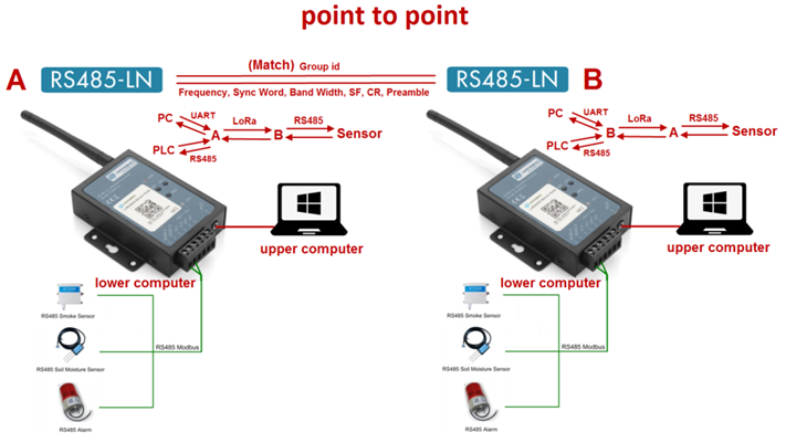
1.2 Configure A's configuration: B's configuration:
AT+GROUPMOD=0 AT+GROUPMOD=0
AT+GROUPID=12345678 AT+GROUPID=12345678
AT+TXCHS=868700000 AT+TXCHS=869000000
AT+RXCHS=869000000 AT+RXCHS=868700000
AT+CFGDEV=0103 00 00 00 04,1 AT+CFGDEV=01 03 00 00 00 02,1
or or
AT+SCHEDULE=0103 00 00 00 04,1 AT+SCHEDULE=01 03 00 00 00 02,1
1.3 Serial port display
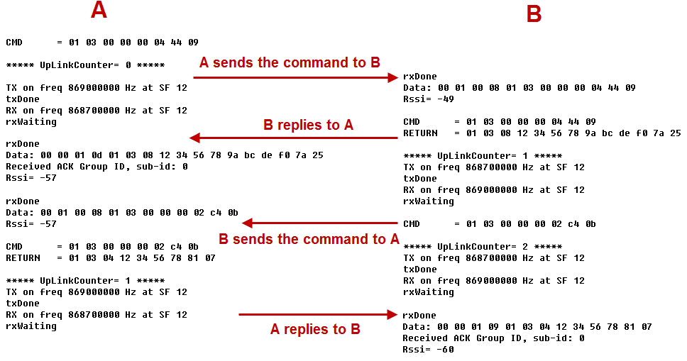
A sends a command to B to query B's RS485 sensor data and display it on A's upper computer.
Similarly, B sends a command to A to query A's RS485 sensor data and display it on B's upper computer.

If the sender does not get the ACK reply from the receiver, it will retransmit up to 4 times, each interval is 10 seconds, and the UplinkCounter of the retransmission will not increase. (Retransmission only occurs when using the AT+CFGDEVcommand or triggering an external interrupt)
**2. Point To Mult-Point **
2.1 Overview
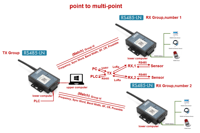
2.2 Configure Configuration of the TX group:
AT+GROUPMOD=0,2
AT+GROUPID=12345678
AT+TXCHS=868700000
AT+RXCHS=869000000
AT+CFGDEV=0103 00 00 00 02,1
or
AT+SCHEDULE=0103 00 00 00 02,1
Configuration for RX group number 1:
AT+GROUPMOD=1,1
AT+GROUPID=12345678
AT+TXCHS=869000000
AT+RXCHS=868700000
Configuration for RX group number 2:
AT+GROUPMOD=1,2
AT+GROUPID=12345678
AT+TXCHS=869000000
AT+RXCHS=868700000
2.3 Serial port display

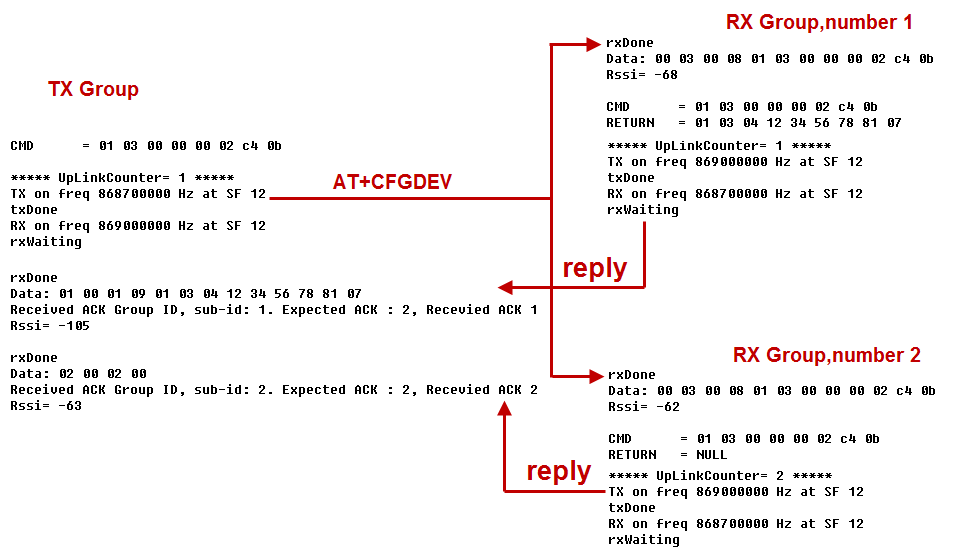
The TX group sends broadcast data to the RX group. After the RX group receives the data, it will reply to the TX group in order from small to large.
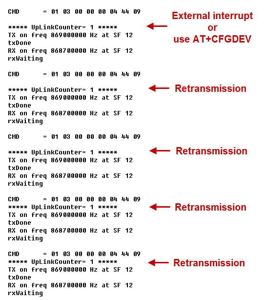
If the sender does not get the ACK reply from the receiver, it will retransmit up to 4 times, each interval is 30 seconds, and the UplinkCounter of the retransmission will not increase.(Retransmission only occurs when using the AT+CFGDEVcommand or triggering an external interrupt)
3 Point to Point (RS485 Pass Through).
3.1 Overview PC --> RS485 to USB adapter --> RS485-LN A<-----LoRa ----> RS485-LN B<-- >RS485 sensor
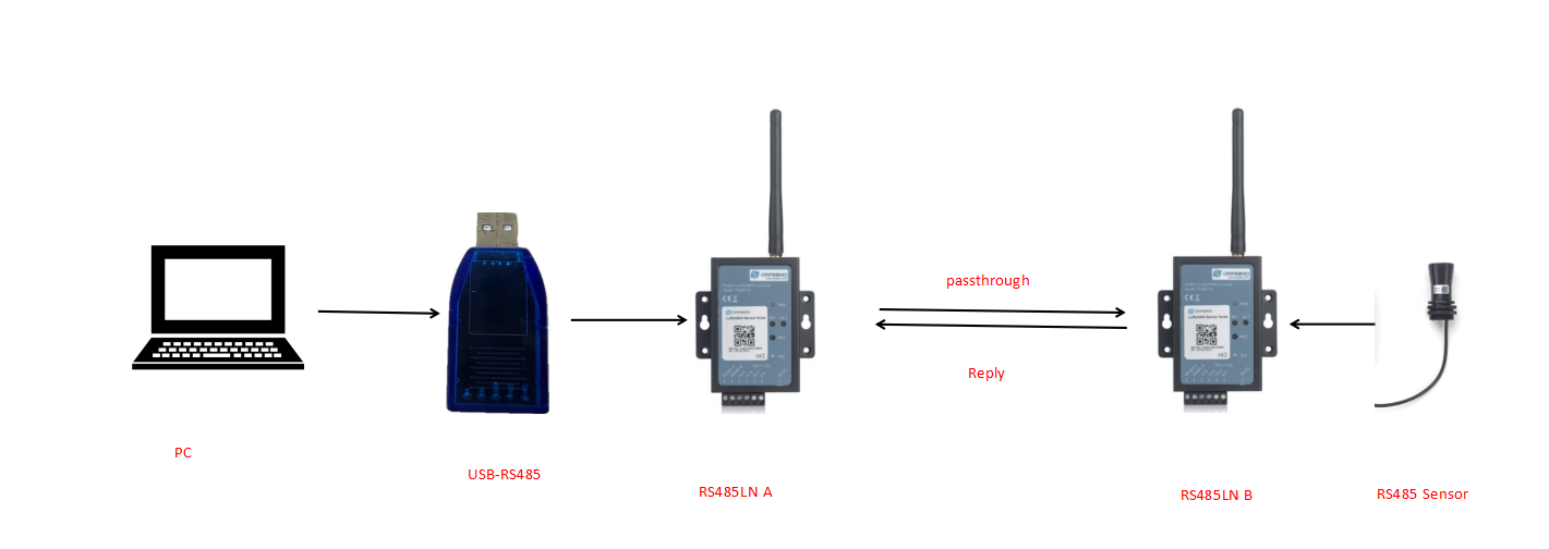
3.2 Configure Configuration of the PC:
RS485 sensor read command
Configuration for RX group number 1:
AT+MOD=1,500
AT+GROUPID=12345678
AT+TXCHS=869000000
AT+RXCHS=868700000
Configuration for RX group number 2:
AT+GROUPID=12345678
AT+TXCHS=869000000
AT+RXCHS=868700000
Configure parameters consistent with the RS485 sensor:
AT+BAUDR=4800
AT+PARITY=0
AT+DATABIT=8
AT+STOPBIT=0
AT+SCHEDULE=0,0
AT+CMDDL=400
3.3 Serial port display
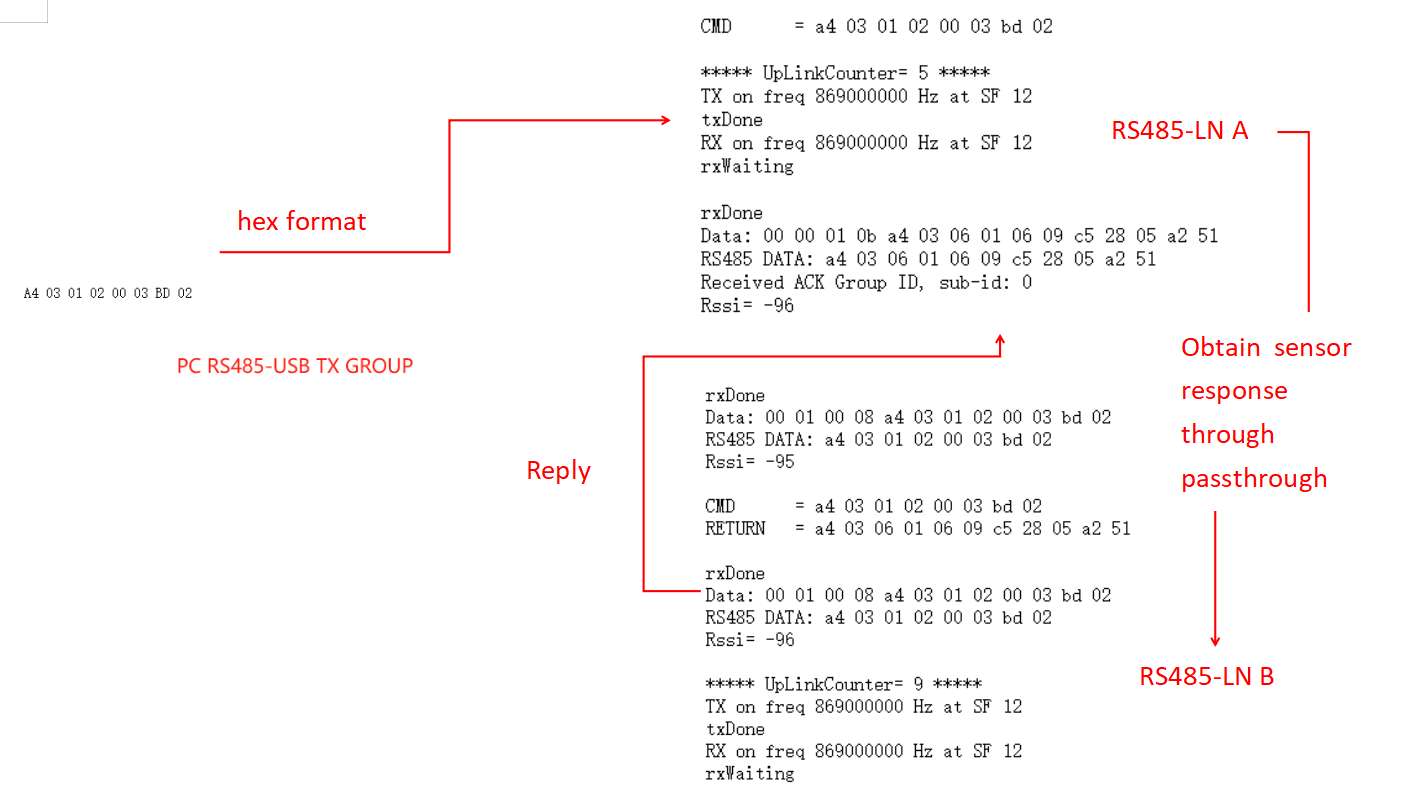
If the sender does not get the ACK reply from the receiver, it will retransmit up to 4 times, each interval is 30 seconds, and the UplinkCounter of the retransmission will not increase.(Retransmission only occurs when using the AT+CFGDEVcommand or triggering an external interrupt)
4. AT command
ATZ**: ** Trig a reset of the MCU
AT+FDR : Reset Parameters to Factory Default, Keys Reserve
AT+FCU : Get or Set the Frame Co unter Uplink
AT+FCD : Get or Set the Frame Counter Downlink
AT+TXP : Get or Set the transmit power, the maximum is 20dBm (default is 14dBm)
AT+SYNC : Get or Set the Sync word [1:0x34,0:0x12] (default is 1)
AT+PMB **: **Get or Set the preamble (default:8)
AT+TXCHS :Get or Set the transmit frequency of TX (default:868700000)
AT+TXSF :Get or Set the spreading factor of TX (7 to 12) (default:12)
AT+RXCHS :Get or Set the transmit frequency of RX (default:869000000)
AT+RXSF :Get or Set the spreading factor of RX (7 to 12) (default:12)
AT+BW :Get or Set the bandwidth [0:125khz,1:250khz,2:500khz] (default:0)
AT+CR :Get or Set the coding rate [1: 4/5, 2: 4/6, 3: 4/7, 4: 4/8] (default:1)
AT+TDC :Get or set the application data transmission interval in ms(default 10 minutes)
AT+VER :Get firmware version number
AT+SEND :Set Custom sent hex data
AT+GROUPMOD :Set or Get the grouping mode of the device (default: 0)
AT+GROUPID :Set or Get the password for matching between TX group and RX group, which can be composed of numbers or characters (default: 12345678)
AT+INTMOD :Get or Set the trigger interrupt mode
AT+BAUDR :Get or set the baud rate of rs485. (default: 9600)
AT+DATABIT :Get or Set databit(7:7 bits,8:8 bits) of rs485 (default: 8)
AT+PARITY :Get or Set parity(0:none,1:odd,2:even) of rs485(default: 0)
AT+STOPBIT :Get or Set stopbit(0:1 bit,1:1.5 bit,2:2 bit) of rs485(default: 0)
AT+CMDDL :Get or Set the delay waiting time after receiving RS485 command (default: 400)
AT+CRCCHECK :Get or set to receive and verify RS485 sensor data (0: Disable,1:CRC16_MODBUS) (default: 1)
AT+SCHEDULE :Each TDC sends command data to the receiver.
AT+CFGDEV :Instantly send RS485 commands to the receiver.
AT+RS485 :Send commands to the local RS485 device.
AT+MOD :Get or set the host send mode.(default: 0)
Example 1:
AT+SEND=01020304will send a payload of 01020304
**Example 2: **
AT+INTMOD=aa (0:Disable,1:falling or rising,2:falling,3:rising) (default: 2)
RS485-LN support external Interrupt uplink since hardware v1.2 release.
Connect the Interrupt pin to RS485-LN INT port and connect the GND pin to V- port. When there is a high voltage (Max 24v) on INT pin. Device will send an lora packet.
**Example 3: **
AT+SCHEDULE:This command will be sent to Group RX during each transmission, Max command length is 14 bytes. The grammar is:
AT+SCHEDULE=xx xx xx xx xx xx xx xx xx xx xx xx,m
xx xx xx xx xx xx xx xx xx xx xx xx: The RS485 command to be sent
m: 0: no CRC, 1: add CRC-16/MODBUS in the end of this command
For example, if we have a RS485 sensor. The command to get sensor value is: 01 03 0B B8 00 02 46 0A. Where 01 03 0B B8 00 02 is the Modbus command to read the register 0B B8 where stored the sensor value. The 46 0A is the CRC-16/MODBUS which calculate manually.
**Example 4: **
AT+CFGDEV :This command will be sent to Group RX.
The grammar is:
AT+CFGDEV=xx xx xx xx xx xx xx xx xx xx xx xx,m
xx xx xx xx xx xx xx xx xx xx xx xx: The RS485 command to be sent
m: 0: no CRC, 1: add CRC-16/MODBUS in the end of this command.
**Example 5: **
AT+RS485: This command will be sent to local RS485 device.
The grammar is:
AT+RS485=xx xx xx xx xx xx xx xx xx xx xx xx,m
xx xx xx xx xx xx xx xx xx xx xx xx: The RS485 command to be sent
m: 0: no CRC, 1: add CRC-16/MODBUS in the end of this command.
Example 6:
AT+MOD=0 Commands are transparently transmitted through UART.
AT+MOD=1,500 Commands are transparently transmitted through RS485. 500 ms after the first character is received from RS485, all characters are commands.
Example 7:
AT+GROUPMOD=0 Set to point to point mode
AT+GROUPMOD=0,aa Set the TX group that controls the number of aa (The maximum value of aa is 8)
AT+GROUPMOD=1,bb Set to the RX group controlled by the TX group, numbered bb(The maximum value of bb is 8)
AT+GROUPMOD=0,2 Set to control the TX group of the two RX groups
AT+GROUPMOD=1,1 Set the RX group numbered 1
AT+GROUPMOD=1,2 Set the RX group numbered 2
5. Data Format
8 bytes of GROUPID +n payload + 4 bytes of checksum
Payload(S12, SF11, SF10 maximum length is 59, SF9 maximum length is 123, SF8, SF7 maximum length is 230):
| Size (bytes) | 1 | 1 | 1 | 1 | payloadsize |
|---|---|---|---|---|---|
| Value | address | request | ACK | payloadsize | command data or return data |
**The first byte: **00 is the broadcast address, 01-08 is the RX group number
The second byte: send request when not 0, not request when it is 0
The third byte: ACK returned to the sender.
The fourth byte: The command length of the sender or the data length of the RS485 sensor returned by the receiver.
The Fifth byte: RS485 command or RS485 return data.
0