AQS01-F
1. Introduction
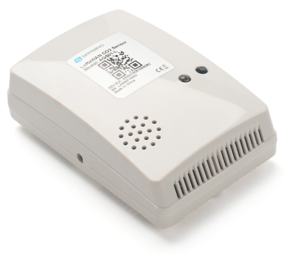
1.1 What is AQS01-F NB-IoT/LTE-M Indoor CO2 Sensor
The Dragino AQS01-F are NB-IoT/LTE-M Indoor CO2 Sensor for Internet of Things solution. It is designed to measure the surrounding environment parameters include: **CO2, Temperature , Relative Air Humidity and Air pressure, **and then upload to IoT server via NB-IoT or CAT-M1 network.
AQS01-F supports different uplink methods include **MQTT, MQTTs, TCP or UDP **for different application requirement. and Support Uplinks to various IoT Servers.
AQS01-F is powered by ER18505 4000mAh battery, It is designed for long term use up to several years. (Real-world battery life depends on the use environment, update period and uplink method. Please check related Power Analyze report).
AQS01-F supports BLE configure and wireless OTA update which make user easy to use.
AQS01-F supports CO2 Alarm and Temperature Alarm features, users can get an alarm for instant notice.
AQS01-F supports Datalog feature, User can retrieve the sensor data from various IoT Servers.
Note*:
*CO2 Alarm and temperature Alarm will decrease a lot the battery life.
*make sure you have NB-IoT or CAT-M1 coverage locally.
1.2 Features
- NB-IoT Bands: B1/B2/B3/B4/B5/B8/B12/B13/B17/B19/B20/B25/B26/B28/B65/B66/B85/B106
- CAT-M1 / LTE-M Bands: B1/B2/B3/B4/B5/B8/B12/B13/B18/B19/B20/B25/B26/B28/B66/B85/B106
- Ultra-low power consumption
- Monitor CO2/Temperature/Relative Humidity/Pressure
- Support CO2 alarm
- Support Datalog Feature
- Uplink via MQTT, MQTTs, TCP or UDP
- GNSS for Location Report
- Support Bluetooth v5.1 remote configure and update firmware
- Uplink on periodically
- Downlink to change configure
- ER18505 4000mAh batteries powered
- Nano SIM card slot for NB-IoT SIM
1.3 Specification
Common DC Characteristics:
- Supply Voltage: built in 4000mAh Li-SOCI2 battery , 2.5v ~ 3.6v
- Operating Temperature: -20 ~ 65°C
CO2 Sensor:
- Sensor: Senseair Sunrise Article No. 006-0-0008** **
- Target gas: Carbon dioxide(CO2)
- Operating principle: Non-dispersiveinfrared(NDIR)
- Operating range: 0-50°C, 0-85% RH(non-condensing)
- Measurement range: 400ppm to 5000 ppm (extended range up to 10000 ppm )
- Accuracy:
- 400-1500ppm ±(30 ppm +3% of reading)
- 1501-2500ppm ±75 ppm
- 2501-5000ppm ±(30 ppm +3% of reading)
- Pressure Compensation
Temperature Sensor:
-
Sensor: bme280** **
-
Range: -20 ~ 65 °C
-
Accuracy: Typ ±1.0@ 0-65 °C
-
Resolution: 0.1°C
Hardware v1.2 and later -
Sensor: sht41** **
-
Range: -40 ~ 125 °C
-
Accuracy: ±0.2°C
-
Resolution: 0.01°C
**Humidity Sensor: **
-
Sensor: bme280
-
Range: 0 ~ 99.9% RH
-
Accurancy: ± 3%RH (20 ~ 80%RH)
-
Resolution: 0.1% RH
-
Long term stability: 0.5 %RH/yr
Hardware v1.2 and later -
Sensor: sht41** **
-
Range: 0 ~ 99.9% RH
-
Accurancy: ± 1.8%RH
-
Resolution: 0.1% RH
**Air Pressure: **
- Sensor: bme280
- Range: 300~1100hPa
- Accuracy: ± 1.0 hPa (0-65 °C)
- Resolution: 0.18Pa
- Long term stability: ±1.0 hPa/yr
NB-IoT Spec:
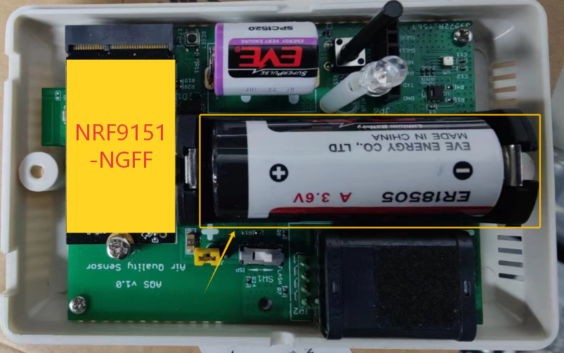
NB-IoT Module: NRF9151-NGFF
Support Bands:
- B1 @H-FDD: 2100MHz
- B2 @H-FDD: 1900MHz
- B3 @H-FDD: 1800MHz
- B4 @H-FDD: 2100MHz
- B5 @H-FDD: 860MHz
- B8 @H-FDD: 900MHz
- B12 @H-FDD: 720MHz
- B13 @H-FDD: 740MHz
- B17 @H-FDD: 730MHz
- B18 @H-FDD: 870MHz
- B19 @H-FDD: 870MHz
- B20 @H-FDD: 790MHz
- B25 @H-FDD: 1900MHz
- B28 @H-FDD: 750MHz
- B66 @H-FDD: 2000MHz
- B70 @H-FDD: 2000MHz
- B85 @H-FDD: 700MHz
Battery:
- Li/SOCI2 un-chargeable battery
- Capacity: 4000mAh
- Self-Discharge: <1% / Year @ 25°C
Power Consumption:
- Sleep Mode: 6uA @ 3.3v
- LoRa Transmit Mode: 125mA @ 20dBm, 82mA @ 14dBm
1.4 Applications
- Smart Buildings & Home Automation
- Logistics and Supply Chain Management
- Smart Metering
- Smart Agriculture
- Smart Cities
- Smart Factory
1.5 Sleep mode and working mode
**Deep Sleep Mode: **Sensor doesn't have any NB-IoT/CAT-M1 activate. This mode is used for storage and shipping to save battery life.
Working Mode: In this mode, Sensor will work as NB-IoT Sensor to Join NB-IoT network and send out sensor data to server. Between each sampling/tx/rx periodically, sensor will be in IDLE mode), in IDLE mode, sensor has the same power consumption as Deep Sleep mode.
1.6 Button & LEDs
| Behavior on ACT | Function | Action |
|---|---|---|
| Send an uplink | If sensor has already attached to NB-IoT/CAT-M1 network, sensor will send an uplink packet, blue led will blink once. Meanwhile, BLE module will be active and user can connect via BLE to configure device. | |
| Active Device | Green led will fast blink 5 times, device will enter OTA mode for 3 seconds. And then start to attach NB-IoT/CAT-M1 network. Green led will solidly turn on for 5 seconds after joined in network. Once sensor is active, BLE module will be active and user can connect via BLE to configure device, no matter if device attach NB-IoT/CAT-M1 network or not. | |
| Deactivate Device | Red led will solid on for 5 seconds. Means device is in Deep Sleep Mode. |
Note: When the device is executing a program, the buttons may become invalid. It is best to press the buttons after the device has completed the program execution.
1.7 BLE connection
AQS01-F support BLE remote configure and firmware update.
BLE can be used to configure the parameter of sensor or see the console output from sensor. BLE will be only activate on below case:
- Press button to send an uplink
- Press button to active device.
- Device Power on or reset.
If there is no activity connection on BLE in 60 seconds, sensor will shut down BLE module to enter low power mode.
1.8 Pin Definitions , Switch & SIM Direction
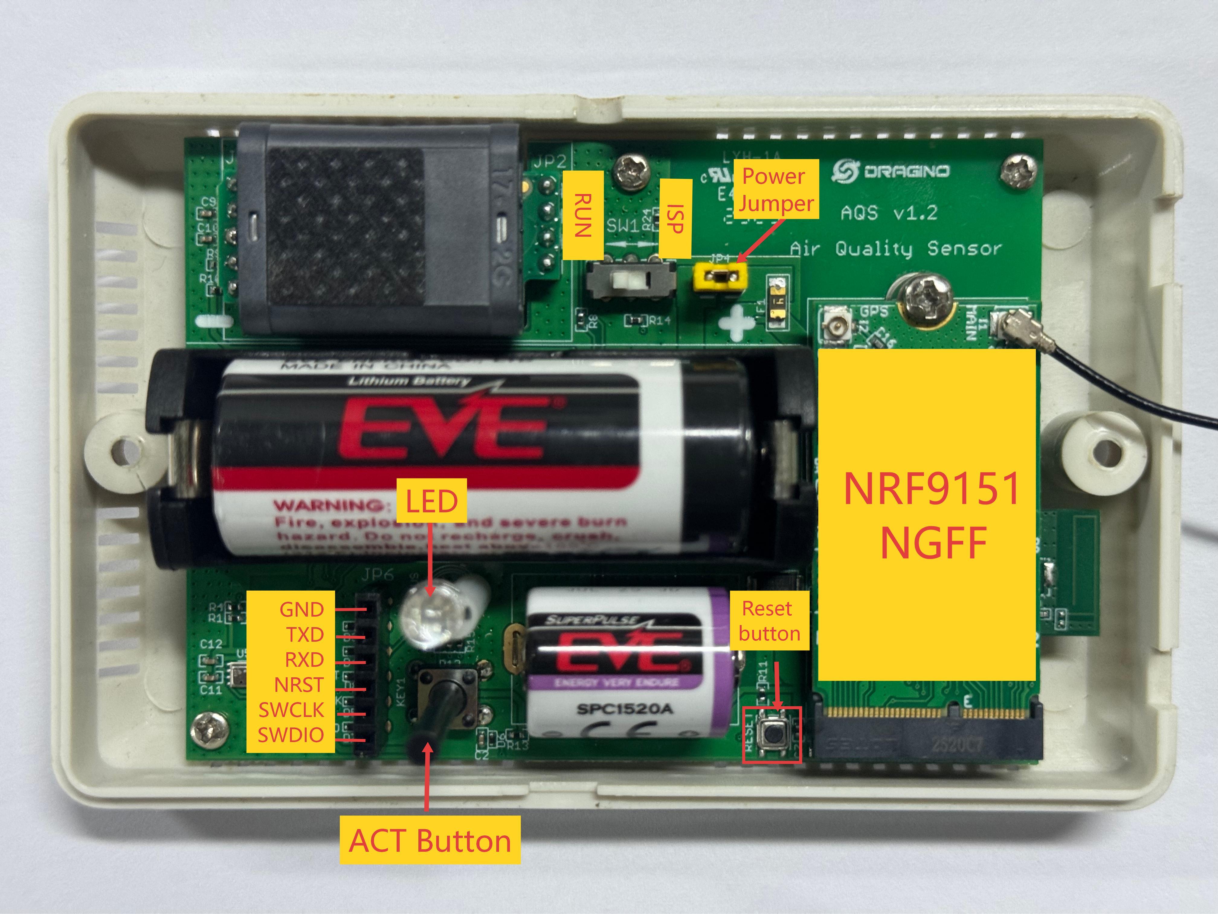
1.8.1 Jumper JP2
Power on Device when put this jumper.
Power off device when take out this jumper
1.8.2 BOOT MODE / SW1
1) ISP: upgrade mode, device won't have any signal in this mode. but ready for upgrade firmware. LED won't work. Firmware won't run.
2) Flash: work mode, device starts to work and send out console output for further debug
1.8.3 Reset Button
Press to reboot the device.
1.8.4 SIM Card Direction
See this link. How to insert SIM Card.
2. Use AQS01-F to communicate with IoT Server
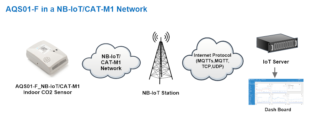
2.1 Send data to IoT server via NB-IoT/CAT-M1 network
The AQS01-F is equipped with a NB-IoT module, the pre-loaded firmware in AQS01-F will get environment data from sensors and send the value to local NB-IoT network via the NB-IoT module. The NB-IoT network will forward this value to IoT server via the protocol defined by AQS01-F.
Below shows the network structure:
There are two version: -GE and -1T version of AQS01-F.
GE Version: This version doesn't include SIM card or point to any IoT server. User needs to use AT Commands to configure below two steps to set AQS01-F send data to IoT server.
-
Install NB-IoT SIM card and configure APN. See instruction of Attach Network.
-
Set up sensor to point to IoT Server. See instruction of Configure to Connect Different Servers.
Below shows result of different server as a glance.
| Servers | Dash Board | Comments |
|---|---|---|
| Node-Red | 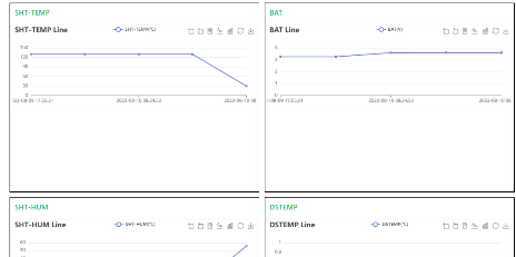 | |
| DataCake | 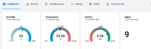 | |
| Tago.IO | ||
| General UDP | Raw Payload. Need Developer to design Dash Board | |
| General MQTT | Raw Payload. Need Developer to design Dash Board | |
| ThingSpeak | 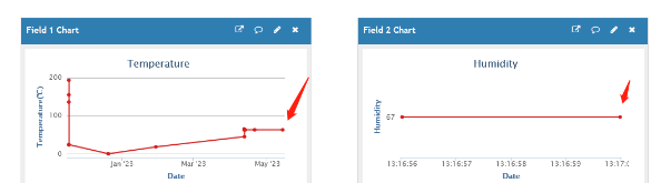 | |
| ThingsBoard | 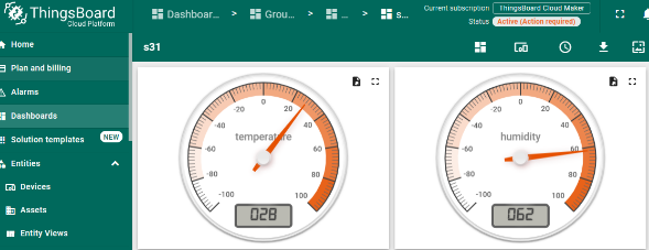 |
1T Version: This version has 1NCE SIM card pre-installed and configure to send value to ThingsEye. User Just need to select the sensor type in ThingsEyeand Activate AQS01-F and user will be able to see data in ThingsEye. See here for ThingsEye Config Instruction.
2.2 Payload Types
To meet different server requirement, AQS01-F supports different payload type.
User can specify the payload type when choose the connection protocol. Example:
AT+PRO=2,0 // Use UDP Connection & Json Payload
AT+PRO=3,0 // Use MQTT Connection & Json Payload
AT+PRO=4,0 // Use TCP Connection & Json Payload
The following describes the latest payload.
Note: The default is AT+QGPS=0 // The GPS function is not enabled. Therefore, the GPS collection time in the following example paylaod does not follow the system time, and the latitude and longitude are 0.
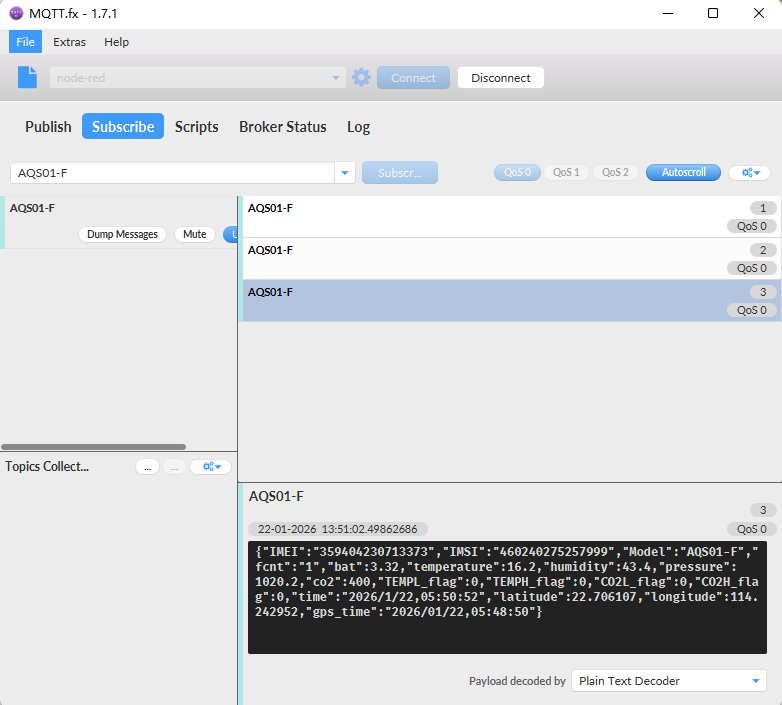
2.2.1 General Json Format
This is the General Json Format. As below:
{"IMEI":"359404230713373","IMSI":"460240275257999","Model":"AQS01-F","fcnt":"1","bat":3.32,"temperature":16.2,"humidity":43.4,"pressure": 1020.2,"co2":400,"TEMPL_flag":0,"TEMPH_flag":0,"CO2L_flag":0,"CO2H_flag":0,"time":"2026/1/22,05:50:52","latitude":22.706107,"longitude":114.242952,"gps_time":"2026/01/22,05:48:50"}
Notice, from above payload:
- Temperature, Humidity, pressure, co2, TEMPL_flag, TEMPH_flag, CO2L_flag, CO2H_flag, latitude, longitude & GPS time are the value at uplink time.
Example:
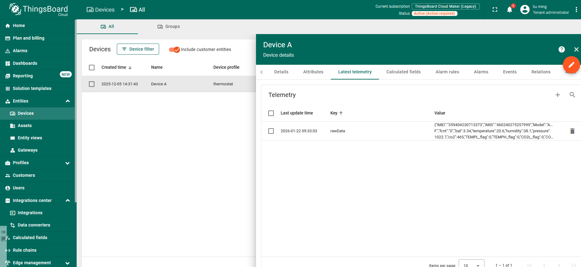
2.2.3 ThingsBoard Payload
Json payload special design for ThingsBoard, it will also configure other default server to ThingsBoard.
{ "topic": "AQS01-F", "payload": { "IMEI": "359404230713373", "IMSI": "460240275257999", "Model": "AQS01-F", "fcnt": "3", "bat": 3.35, "temperature": 20.8, "humidity": 37.3, "pressure": 1022.5, "co2": 473, "TEMPL_flag": 0, "TEMPH_flag": 0, "CO2L_flag": 0, "CO2H_flag": 0, "time": "2026/1/22,01:20:51", "latitude": 0.0, "longitude": 0.0, "gps_time": "00/00/00,00:00:00" } }
3. Configure AQS01-F
3.1 Configure Methods
AQS01-F supports below configure method:
-
AT Command via Bluetooth Connection (Recommended): BLE Configure Instruction.
-
AT Command via UART Connection : See UART Connection.
3.2 Serial Access Password
After the Bluetooth or UART connection is successful, use the Serial Access Password to enter the AT command window.
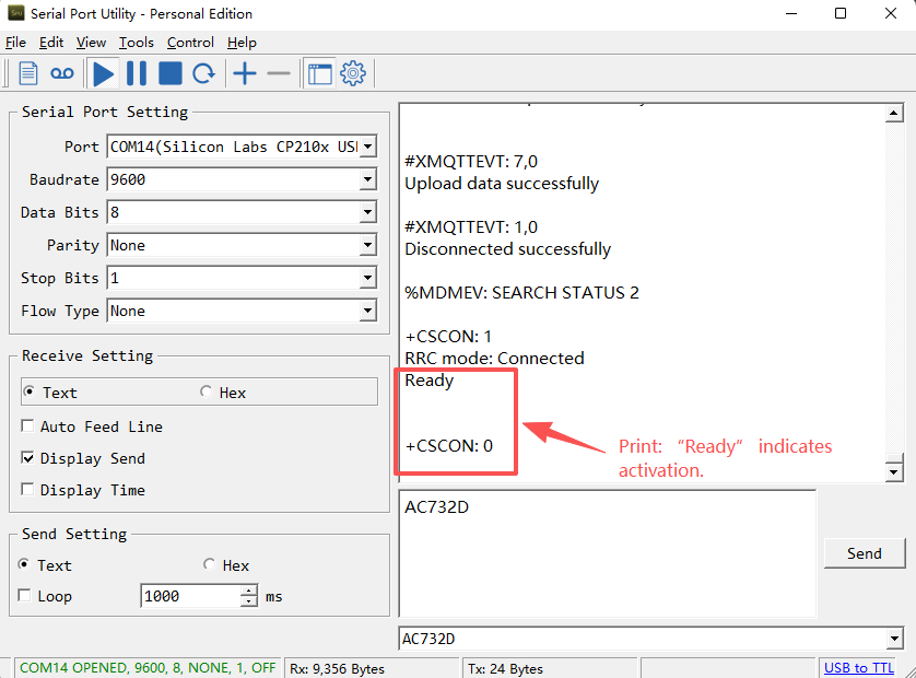
Note:
1. After connecting the device via serial port or Bluetooth, press the ACT button on the device to activate its serial port functionality. Otherwise, even if the connection is successful, the serial port function will remain unavailable.
2. Each configuration requires pressing the ACT button once to disable the serial port function; otherwise, the device will remain in a power-consuming state.
3. The serial port function will automatically deactivate during each upload. To reactivate it when needed, press the ACT button once.
Using the serial port as an example:
The label on the box of the node will print the initial password: AT+PIN=xxxxxx, and directly use the six-digit password to access the AT instruction window.
Note: You must add two carriage returns after the command for the device to recognize it.
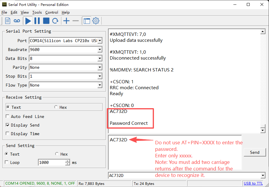
If you need to change the password, use AT+PWORD=xxxxxx (6 characters), -F nodes only support lowercase letters.
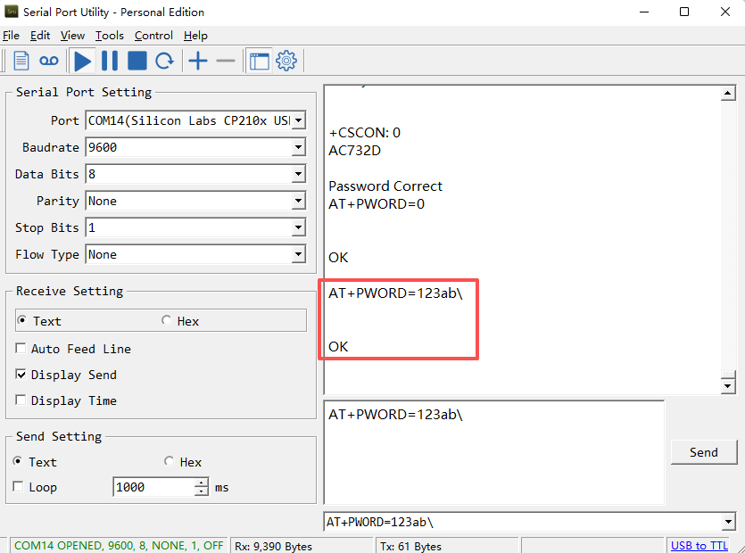
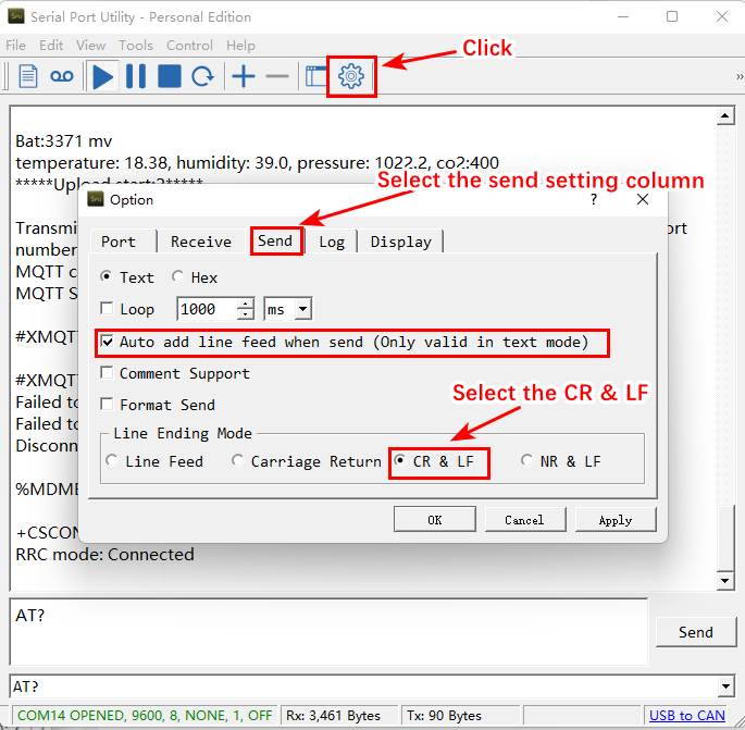
Note: Users must configure Serial Assistant to automatically add a line break when sending commands. Without this line break, the AT commands you send will be invalid. (Using Serial Assistant as an example)
3.3 AT Commands Set
AT+<CMD>? : Help on <CMD>
AT+<CMD> : Run <CMD>
AT+<CMD>=<value> : Set the value
AT+<CMD>=? : Get the value
AT+MODEL : Get module information
AT+CFGMOD : Working mode selection
AT+DEUI : Get or set the Device ID
AT+CFG : Print all settings
AT+SERVADDR: Get or Set the Server address
AT+TDC : Get or set the application data transmission interval in s
AT+APN : Get or set the APN
AT+5VT : Get or Set extend the time of 5V power
AT+PRO : Get or Set usage agreement (2:UDP,3:MQTT,4:TCP)
AT+RXDL : Get or Set the receiving time
AT+EXT : Get or Set Count value
AT+SHTEMP:Get or Set alarm of shtemp
AT+SHHUM:Get or Set alarm of shthum
AT+GETSENSORVALUE : Returns the current sensor measurement
AT+DNSCFG : Get or Set DNS Server
AT+CSQTIME : Get or Set the time to join the network
AT+GDNS : Get or Set the DNS
AT+SLEEP : Get or Set the sleep mode
AT+IPTYPE : Set the IPv4 or IPv6
AT+QSW : Power on and power off BG95 module
AT+CLOCKLOG: Get or set SHT record time
AT+QBAND: Get or set Frequency Band
AT+IOTMOD: Configure Network Category to be Searched for under LTE RAT
AT+DOWNTE: Get or set the conversion between the standard version and 1T version downlinks
AT+REDPT: Get or Set the function of reconnecting the network to send data
AT+DEBUG: Get or Set the debug mode
MQTT Management
AT+CLIENT : Get or Set the MQTT clientID
AT+UNAME : Get or Set the MQTT Username
AT+PWD : Get or Set the MQTT password
AT+PUBTOPIC: Get or set MQTT publishing topic
AT+SUBTOPIC: Get or set MQTT subscription topic
AT+MQOS : Set the QoS level of MQTT
AT+TLSMOD : Get or Set the TLS mode
GPS
AT+GTIME : Extend the time to turn on GNSS
AT+QGPS : Turn off and on GPS
AT+QGTDC : Get or set GPS positioning interval in units of h
Information
AT+FDR1 : Reset parameters to factory default values except for passwords
AT+FDR : Reset Parameters to Factory Default
AT+PWORD : Get or set the System password
AT+LDATA : Get the last upload data
AT+CDP : Read or Clear cached data
AT+PDTA: Print the sector data from start page to stop page
AT+PLDTA: Print the last few sets of data
AT+CLRDTA: Clear the storage, record position back to 1st
AT+GETLOG : Print serial port logs
ATZ : Trig a reset of the MCU
AT+UDPMOD: Get or set UDP working mode
AT+SFNT: Get or set search for network time
AT+CALMOD: Set the calibration mode(0:Disable ABC calibration;1:Enable ABC calibration mode)
AT+CALCMD: Set calibration command
AT+TEMPALARM: Get or Set alarm of bme280temp
AT+CO2ALARM: Get or Set alarm of co2
AT+ATDC: Get or set the application minimum alarm interval in min
3.4 Test Uplink and Change Update Interval
By default, Sensor will send uplinks every 20 min.
User can use below commands to change the uplink interval.
AT Command: AT+TDC
Example: AT+TDC=1200 // Set Update Interval to 1200 seconds
Downlink Commands: 0x01
Format: Command Code (0x01) followed by 3 bytes.
Example: 12 hours= 43200 seconds 43200(D)=0xA8C0(H)
Downlink Payload: `01 00 A8 C0` // AT+TDC=43200, Set Update Interval to 12 hours.
Note: User can also push the button for more than 1 second to activate an uplink.
3.5 Set the receiving time
Feature: Extend the receiving time
AT Command: AT+RXDL
Example: AT+RXDL=1000 // Set the receiving time delay to 1000ms
Downlink Commands: 0x03
Format: Command Code (0x03) followed by 3 bytes.
Example: Downlink Payload: 03 00 03 E8// AT+RXDL=1000
3.6 Reset
Feature: Trig a reset of the MCU.
AT Command: ATZ
Downlink Commands: 0x04FF
3.7 +5V
Feature: Set extend the time of 5V power.
AT Command: AT+5VT
Example: AT+5VT=2000 // Set extend the time of 5V power to 2000 ms
Downlink Commands: 0x05
Format: Command Code (0x05) followed by 3 bytes.
Example: Downlink Payload: 05 00 07 D0// AT+5VT=2000
3.8 Set the QoS level
This command is used to set the QoS level of MQTT.
AT command:
- **AT+MQOS=xx **// 0~2
Downlink command: 0x07
Format: Command Code (0x07) followed by 1 byte.
Ex1: Downlink payload: 0x0700 // AT+MQOS=0
Ex2: Downlink payload: 0x0701 // AT+MQOS=1
3.9 Set the TLS mode
Refer to this link (MQTT Connection to send data)to use the TLS mode.
AT Command: AT+TLSMOD
**Example 1: ** AT+TLSMOD=0,0 // Disable TLS Mode.
Example 2: AT+TLSMOD=1,0 // No authentication
                 AT+TLSMOD=1,1   // Perform server authentication

                 AT+TLSMOD=1,2   // Perform server and client authentication if requested by the remote server
Downlink command: 0x09
Format: Command Code (0x09) followed by 2 bytes.
Example1: Downlink Payload: 09 00 00// AT+TLSMOD=0,0
Example2: Downlink Payload: 09 01 02// AT+TLSMOD=1,2
3.10 Set GNSS open time
Extend the time to turn on GNSS. The automatic GPS location time is extended when the node is activated.
AT Command: AT+GTIME
Example: AT+GTIME=30 // Set the GPS positioning time to 30 seconds
Downlink command: 0x10
Format: Command Code (0x10) followed by 2 bytes.
Example: Downlink Payload: 10 00 1E// AT+GTIME=30
3.11 Turn on/off GPS
**AT Command: AT+QGPS **
**Ex1: **AT+QGPS=0 // Turn off GPS
**Ex2: **AT+QGPS=1 // Turn on GPS
Downlink command: 0x11
Format: Command Code (0x11) followed by 1 byte.
Example: Downlink Payload: 11 01// AT+GPS=1
3.12 Set GPS positioning interval
Feature: Set GPS positioning interval (unit: hour).
When GPS is enabled, the node automatically locates and uplinks each time it passes GTDC time after activation.
AT Command: AT+QGTDC
Example: AT+QGTDC=24 // Set the GPS positioning interval to 24h.
Downlink command: 0x12
Format: Command Code (0x12) followed by 3 bytes.
Example: 24 hours: 24(D)=0x18(H)
Downlink Payload: `12 00 00 18`// AT+QGTDC=24
3.13 Set Temperature Alarm Threshold
- AT Command:
AT+TEMPALARM=min,max (Among them, 100 is an invalid value, which means not set)
- When min=100, and max≠100, Alarm higher than max
- When min≠100, and max=100, Alarm lower than min
- When min≠100 and max≠100, Alarm higher than max or lower than min
Example:
AT+TEMPALARM=100,30 // Alarm when temperature higher than 30.
- Downlink Payload:
0x(0C 01 64 1E) // Set AT+TEMPALARM=100,30
(note: 3rd byte= 0x64 for low limit(not set), 4th byte = 0x1E for high limit: 30)
3.14 Set CO2 Alarm Threshold
The CO2 alarm function detects CO2 once every minute, so it consumes more power.
- AT Command:
AT+CO2ALARM=min,max (Among them, 0 is an invalid value, which means not set)
- When min=0, and max≠0, Alarm higher than max
- When min≠0, and max=0, Alarm lower than min
- When min≠0 and max≠0, Alarm higher than max or lower than min
Example:
AT+CO2ALARM=400,0 // Alarm when humidity lower than 400.
- Downlink Payload:
0x(0C 02 01 90 00 00) // Set AT+CO2ALARM=400,0
(note: 3rd byte+4rd byte= 0x0190 for low limit (400ppm), 5th byte+6rd byte = 0x00 for high limit (not set))
3.15 Set Alarm Interval
The shortest time of two Alarm packet. (unit: min)
- AT Command:
AT+ATDC=20 // The shortest interval of two Alarm packets is 20 minutes, Means if there is an alarm packet uplink, there won't be another one in the next 20 minutes.
- Downlink Payload:
0x(0D 14) **---> ** Set AT+ATDC=0x 14 = 20 minutes
3.16 Configure Network Category to be Searched for under LTE RAT.
AT command: AT+IOTMOD=xx
xx: 0: eMTC
        **1:** NB-IoT

        **2:** eMTC and NB-IoT
3.17 Factory data reset
Two different restore factory Settings configurations.
AT command:
- **AT+FDR **// Reset Parameters to Factory Default.
- **AT+FDR1 **// Reset parameters to factory default values except for passwords.
3.18 Print last few data entries
Feature: Print the last few data entries
AT command: AT+PLDTA
| Command Example | Response |
|---|---|
| AT+PLDTA=5 Print last 5 entries | 0001 2026/1/22 00:37:47 3371 temp:18.3 hum:39.0 pres:1022.1 co2:400 0002 2026/1/22 00:57:48 3375 temp:18.7 hum:39.0 pres:1022.3 co2:400 0003 2026/1/22 01:19:26 3328 temp:20.7 hum:37.9 pres:1022.4 co2:512 0004 2026/1/22 01:32:50 3339 temp:20.6 hum:38.1 pres:1022.7 co2:465 0005 2026/1/22 01:52:50 3351 temp:20.9 hum:38.1 pres:1023.0 co2:517 0006 2026/1/22 02:12:50 3351 temp:20.5 hum:37.3 pres:1022.9 co2:433 0007 2026/1/22 02:32:51 3363 temp:20.7 hum:38.7 pres:1023.1 co2:535 0008 2026/1/22 02:46:24 3339 temp:20.9 hum:37.3 pres:1023.1 co2:478 OK |
**Downlink Command: **
No downlink commands for feature
3.19 Print data entries base on page
Feature: Print the sector data from start page to stop page.
AT command: AT+PDTA
| Command Example | Response |
|---|---|
| AT+PDTA=1,1 Print page 1 to 1 | AT+PDTA=1,1 E8000 2026/1/17 08:00:52 3543 temp:26.7 hum:32.8 pres:1006.4 co2:400 E8010 2026/1/17 08:12:48 0 temp:26.7 hum:32.1 pres:1006.4 co2:412 E8020 2026/1/17 08:14:00 3540 temp:26.7 hum:32.1 pres:1006.5 co2:410 E8030 2026/1/17 08:15:32 3536 temp:26.8 hum:31.5 pres:1006.5 co2:400 E8040 2026/1/17 08:22:16 3536 temp:26.7 hum:32.0 pres:1006.4 co2:401 E8050 2026/1/17 08:23:13 3532 temp:26.7 hum:31.9 pres:1006.4 co2:400 E8060 2026/1/17 08:25:26 3528 temp:26.9 hum:35.5 pres:1006.4 co2:405 E8070 2026/1/17 08:27:24 3524 temp:27.4 hum:31.5 pres:1006.4 co2:589 OK |
**Downlink Command: **
No downlink commands for feature
3.20 Clear Flash Record
Feature: Clear flash storage for data log feature.
AT command: AT+CLRDTA
| Command Example | Function | Response |
|---|---|---|
| AT+CLRDTA | Clear date record | Stop Tx events,Please wait for the erase to complete Clear all stored sensor data... Start Tx events OK |
Downlink Command: 0x32
- Example: 0x32 00 // Same as AT+CLRDTA
3.21 Working mode selection
Feature: Set default mode.
AT command: AT+CFGMOD
| Command Example | Function |
|---|---|
| AT+CFGMOD=1 | default mode |
Downlink Command: 0x02
- Downlink command: 02 01 // Equal to AT+CFGMOD=1
3.22 DataLog feature
Unix TimeStamp
AQS01-F uses Unix TimeStamp format based on
User can get this time from link: https://www.epochconverter.com/ :
Below is the converter example
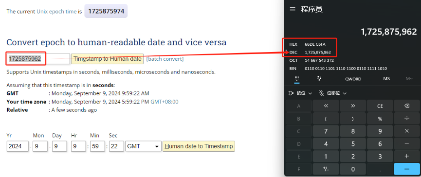
So, 1725875962 means that the current time is Monday, September 9, 2024 at 9:59 AM.
Poll sensor value
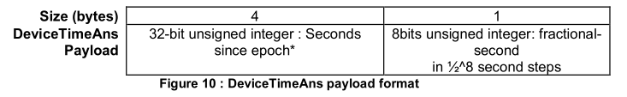
User can poll sensor value based on timestamps from the server. Below is the downlink command.
| 1 byte | 4 bytes | 4 bytes |
|---|---|---|
| 31 | Timestamp start | Timestamp end |
Timestamp start and Timestamp end use Unix TimeStamp format as mentioned above. Devices will reply with all data log during this time period.
For example, downlink command 31 6971 715E 6971 8FA4
Is to check 2026/1/22 00:37:00 to 2026/1/22 02:47:00's data
Datalog Uplink payload
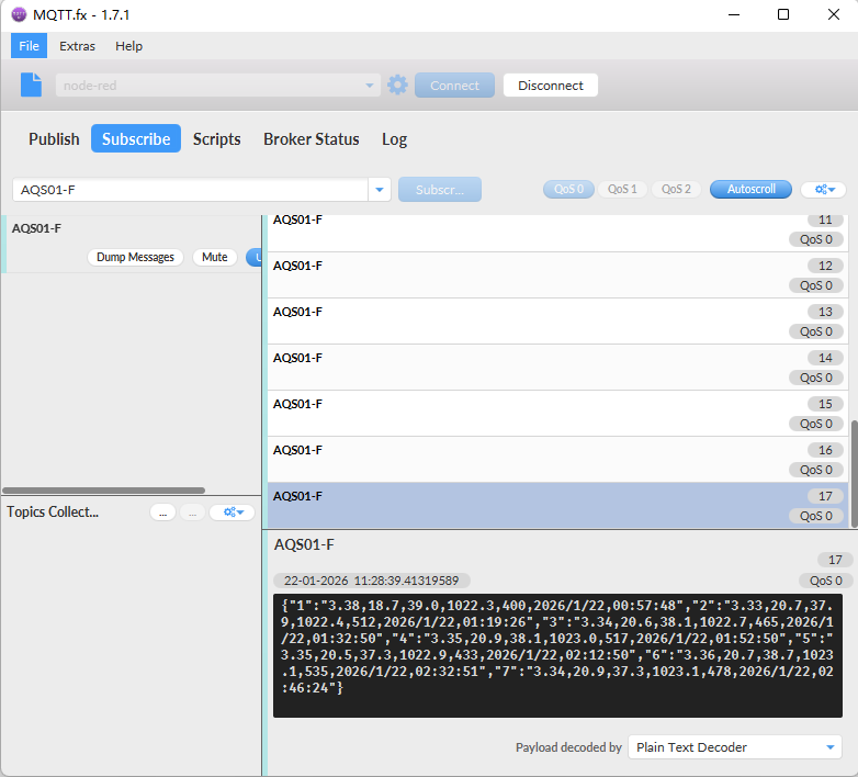
**Function Description: **This feature is only used when the clock logging feature is turned on. one uplink packet can send 64 groups of stored data totaling 512 bytes.
Example(For MQTT.fx):
If user sends below downlink command:
Where : Start time: 6971715E= time 26/1/22 00:37:00
Stop time: 69718FA4= time 26/1/22 02:47:00
AQS01-F will uplink this payload.
3.23 Calibration command
Note: If the device is not calibrated for the first time, there will be a certain degree of drift.
After having performed the calibration,all following measurements will use the adjusted calibration parameters.
3.23.1 Restore factory Calibration (AT+CALCMD=0)
Restores calibration parameters factory calibration values.
**Downlink Payload: **0x0F 00
3.23.2 Forced ABC Calibration (AT+CALCMD=1)
Sensor will perform an ABC calibration after receiving this command if sensor has valid ABC data.The command can be used if one for some reason wants to do an ABC adjustment before one ABC period has passed(when a normal ABC calibration is done).
**Downlink Payload: **0x0F 01
3.23.3 Target Calibration (AT+CALCMD=2 Equivalent to AT+CALCMD=2,400)
Target concentration calibration assumes that sensor is put into a target environment with a known CO2 concentration. Such as outdoor fresh air 400ppm.
**Downlink Payload: **0x0F 02 ==> AT+CALCMD=2
                                 0x0F 02 01 90 ==\> AT+CALCMD=2,400

                                 0x0F 02 01 F4 ==\> AT+CALCMD=2,500
3.23.4 Background Calibration (AT+CALCMD=3)
A “fresh air” baseline environment is by default 400 ppm at normal ambient atmospheric pressure by sea level. It can be referenced in a crude way by placing the sensor in direct proximity to outdoor air, free of combustion sources and human presence, preferably during either by open window or fresh air inlets or similar. Calibration gas by exactly 400ppm can be purchased and used. Background calibration and ABC calibration share the same target value (fresh air = 400ppm).
**Downlink Payload: **0x0F 03
3.23.5 Zero Calibration (AT+CALCMD=4)
Zero-calibrations are the most accurate recalibration routine. A zero-ppm environment is most easily created by flushing the optical cell of the sensor module and filling up an encapsulating enclosure with nitrogen gas, N2, displacing all previous air volume concentrations. Another less reliable or accurate zero reference point can be created by scrubbing an airflow using e.g. Soda lime.
**Downlink Payload: **0x0F 04
3.24 calibration mode
3.24.1 Enabled ABC Calibration (AT+CALMOD=1, default)
The Automatic Baseline Correction algorithm is a proprietary Senseair method for referencing to “fresh air” as the lowest, but required stable, CO2-equivalent internal signal the sensor has measured during a set time period. This time period by default is 180hrs as to catch low-occupancy and other lower-emission time periods and favourable outdoor wind-directions and similar which can plausibly and routinely expose the sensor to the most true fresh air environment. If such an environment can never be expected to occur, either by sensor locality or ever-presence of CO2 emission sources, or exposure to even lower concentrations than the natural fresh air baseline, then ABC recalibration can’t be used. In each new measurement period, the sensor will compare it to the stored one at the ABC parameters registers, and if new values show a lower CO2-equivalent raw signal while also in a stable environment, the reference is updated with these new values. The ABC algorithm also has a limit on how much it is allowed to change the baseline correction offset with, per each ABC cycle, meaning that self-calibrating to adjust to bigger drifts or signal changes may take more than one ABC cycle.
**Downlink Payload: **0x0E 01
3.24.2 Disabled ABC Calibration (AT+CALMOD=0)
If the device is in a greenhouse or enclosed environment, it is recommended to turn off ABC calibration. And use Target Calibration for calibration.
**Downlink Payload: **0x0E 00
3.24.3 Button CO2 calibration function (Equivalent to AT+CALCMD=3)
The first step is to put your device into sleep mode. Press the button five times quickly and the device will light up solid red for 5 seconds.
In the second step, take the device outside to an environment without combustion sources and people, let it sit for a few minutes, and then press the button three times quickly. The calibration is complete after the blue light stays on for 5 seconds.
The last step is to reset the device, press and hold the button until the green light flashes.
4. Battery & Power Consumption
4.1 Battery Life
In a normal 20 minutes uplink situation , the battery life can last from 2 ~ 8 years depends on signal environment. The Alarm feature will reduce the battery life a lot .
See below link for detail information about the battery life calculation.
Battery Info & Power Consumption Analyze .
To be updated
4.2 Replace Battery
AQS01-F uses an ER18505 battery. If the battery is running out, User can purchase an ER18505 battery and replace. Make sure don't mess the + & - position.
5. Firmware Update
This section describes how to update the firmware on the AQS01-F device. Firmware updates allow users to:
- Add new features
- Fix known bugs
The firmware binary and corresponding changelog can be downloaded from the following link: Firmware download link
There are two methods to update the firmware:
- Over-the-Air (OTA) via HTTP protocol
- Via J-Link interface (requires hardware connection)
5.1 Over-the-Air (OTA) Firmware Update via HTTP
Note: Users can upload the firmware binary to any public HTTP server (not a local/private network address) that the device can access, then use the following method to upgrade
Perform the following steps:
① Place the firmware binary (e.g., AQS01-F.bin) on an HTTP-accessible server.
② Use a serial port or send the following command to the device: AT#XFOTA=1,"<firmware_url>"
Example:
AT#XFOTA=1,"http://repo.dragino.com/release/NB/AQS01-F.bin
After the node receives the upgrade command via downlink, it will perform the upgrade automatically as shown below:
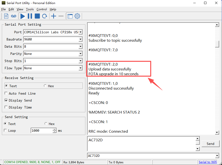
5.2 Firmware Update via J-Link Interface
Use this method if OTA is not available or if the device is unresponsive.
**Prerequisites: **
- An ARM emulator (J-Link compatible)
- Firmware update tool: nRF Connect for Desktop
**Note: During the installation of nRF Connect for Desktop, you will be prompted to install the J-Link driver. You must confirm the installation; otherwise, the J-Link external tool will not be recognized. **
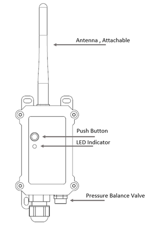
5.2.1 Hardware Connection
Remove the NRF9151 module from the motherboard and connect it to the J-Link as illustrated below:
NRF9151 Module Hardware Wiring:

5.2.2 Software Setup
Launch nRF Connect for Desktop.
Locate and download the Programmer tool from the available apps (see below):
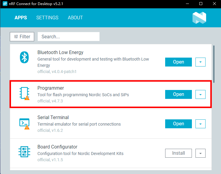
After download, click OPEN to enter the Programmer interface.
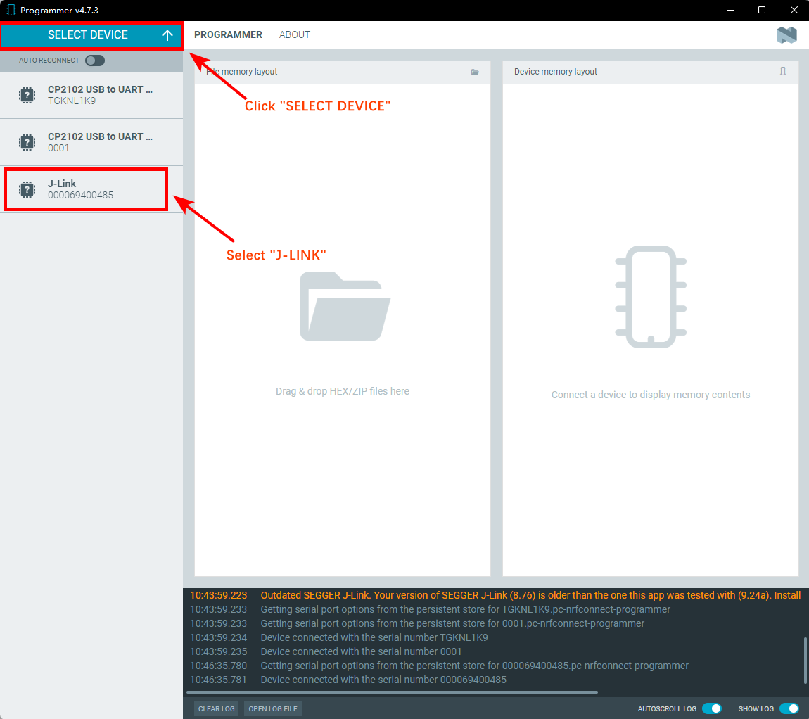
5.2.3 Firmware Update Steps
Click "SELECT DEVICE" → Select "J-Link"
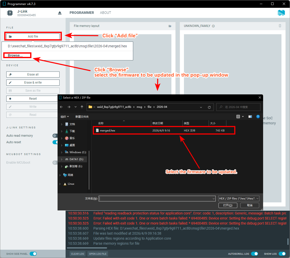
On the main screen, click "Add file", then click "Browse" and select the firmware you want to update in the pop-up window.
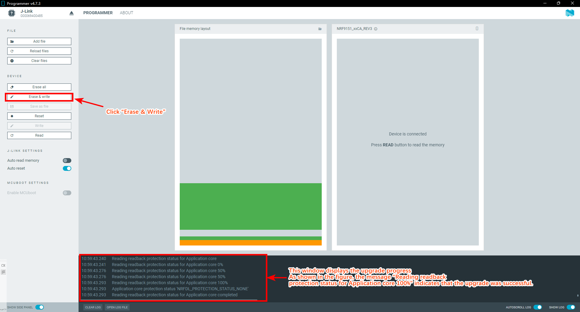
Click “Erase & Write” to begin the update
6. FAQ
6.1 How can I access the NRF9151-NGFF AT Commands?
User can access to NRF9151-NGFF directly and send AT Commands.
See NRF9151-NGFF AT Command set
6.2 General Manual for -F models
To be updated.
7. Order Info
Part Number: AQS01-F-XX
XX:
-
GE: General version ( Exclude SIM card)
-
1T: with 1NCE* 10 years 500MB SIM card and Pre-configure to ThingsEye server
8. Packing Info
Package Includes:
-
AQS01-F Indoor CO2 Sensor x 1
-
External antenna x 1
Dimension and weight:
-
Device Size: cm
-
Device Weight: g
-
Package Size / pcs : cm
-
Weight / pcs : g
9. Support
-
Support is provided Monday to Friday, from 09:00 to 18:00 GMT+8. Due to different timezones we cannot offer live support. However, your questions will be answered as soon as possible in the before-mentioned schedule.
-
Provide as much information as possible regarding your enquiry (product models, accurately describe your problem and steps to replicate it etc) and send a mail to Support@dragino.cc.
0