PF52
1. Introduction
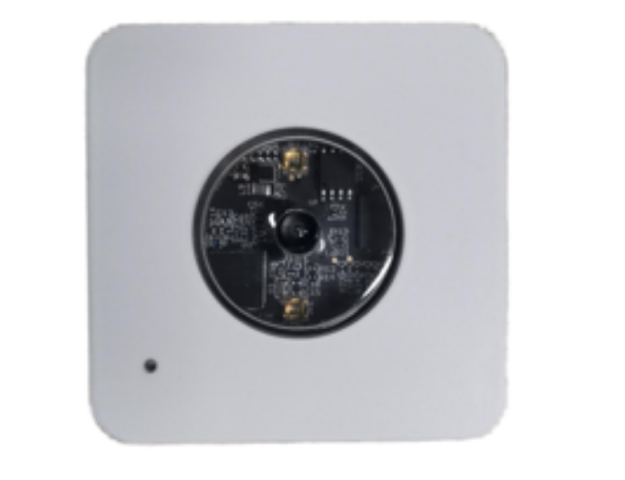
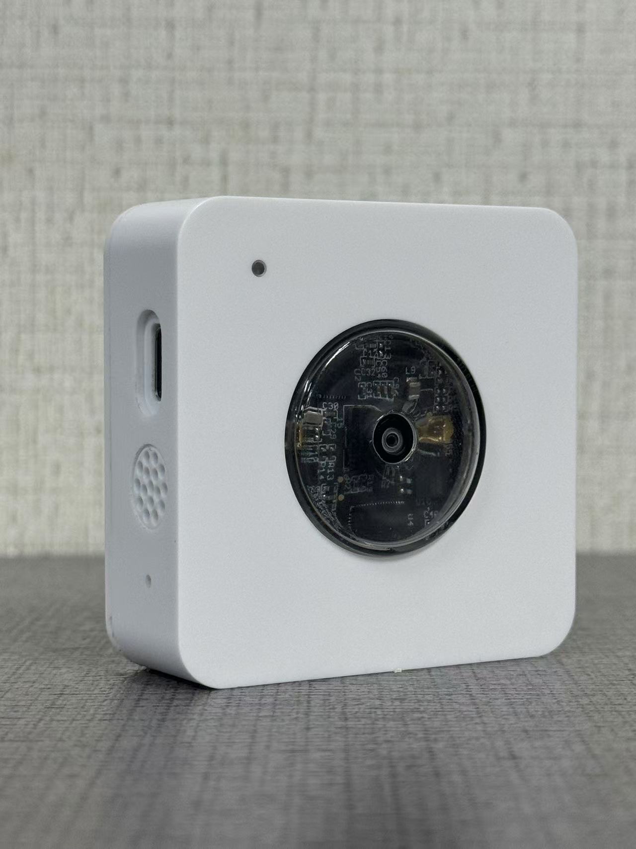
1.1 What is PF52 People Counting Sensor
The PF52 LoRaWAN AI People Counter redefines remote monitoring by merging edge AI vision with LoRaWAN connectivity. Designed for continuous operation with external power, it delivers a robust, maintenance-free solution for accurate 24/7 people counting in fixed installations.
Its core innovation is on-device AI processing. The sensor analyzes video locally to count people, outputting only anonymous data. This ensures both high accuracy and inherent privacy protection, as no images or personal data are ever stored or transmitted over the network.
The combination of AI intelligence and LoRaWAN's long range provides unparalleled deployment flexibility. You gain the precision of a visual counter without the need for Wi-Fi or complex wiring, making it ideal for providing reliable, data-driven insights into foot traffic and occupancy across vast or hard-to-reach areas.
1.2 Features
- Accurate AI Counting: Advanced algorithm ensures precise, trustworthy people count data.
- Built-in Privacy: Processes video locally and outputs only anonymous counts - no images are ever stored or transmitted.
- Long-Range Connectivity: Leverages LoRaWAN® to transmit data over kilometers, going far beyond Wi-Fi range limitations.
- Continuous Operation: Designed for external power supply, enabling maintenance-free, 24/7 operation in permanent installations.
1.3 Specification
Common DC Characteristics:
- DC power supply 5v
- Operating Temperature: 10 ~ 55°C
Camera:
- Angle: 110°
- Image size: 64kb
- Image resolution: 640x480
- Power Consumption: 206.1mW
- Supply Voltage: DC5V
- Idel Mode: 6uA
- Take Photo: 41.22 mA and 3171 ms
- Cable Length: 150cm
- Dimension: 46.2x29x13.8 mm
- Waterproof level: IP52
LoRa Spec:
- Frequency Range, Band 1 (HF): 862 ~ 1020 Mhz
- Max +22 dBm constant RF output vs.
- RX sensitivity: down to -139 dBm.
- Excellent blocking immunity
1.5 Storage & Operation Temperature
- Storage Temperature: -20 ~ 60 °C
- Operating Temperature: 0 ~ 50°C
1.6 Applications
- Retail Analytics
- Smart Building Management
- Public Space Monitoring
- Workplace & Office Optimization
- Security & Access Monitoring
2. Configure PF52 to connect to LoRaWAN network
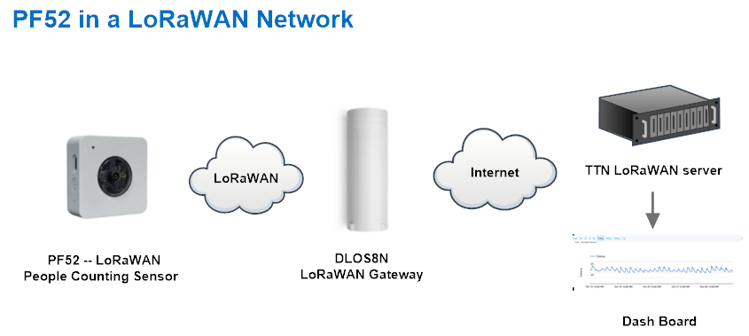
2.1 How it works
The PF52 is configured as LoRaWAN OTAA Class A mode by default. It has OTAA keys to join LoRaWAN network. To connect a local LoRaWAN network, you need to input the OTAA keys in the LoRaWAN IoT server and press the button to activate thePF52. It will automatically join the network via OTAA and start to send the sensor value. The default uplink interval is 20 minutes.
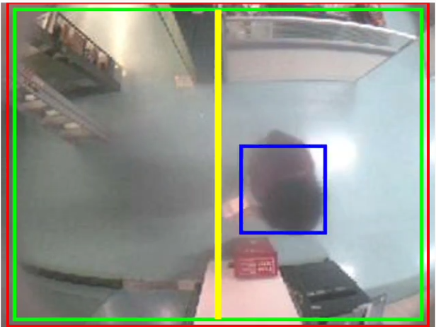
The LED light is at the upper left for a positive viewing angle.When the character crosses the horizontal line in the middle, the count increases by one.
For details, please see the case.
2.2 Example to join LoRaWAN network
This section shows an example for how to join the TheThingsNetwork LoRaWAN IoT server. Usages with other LoRaWAN IoT servers are of similar procedure.
Assume the DLOS8N is already set to connect to TTN V3 network . We need to add the PF52 device in TTN V3 portal.
Currently, PF52 only supports manual registration with The Things Stack.
2.2.1 Creating an application
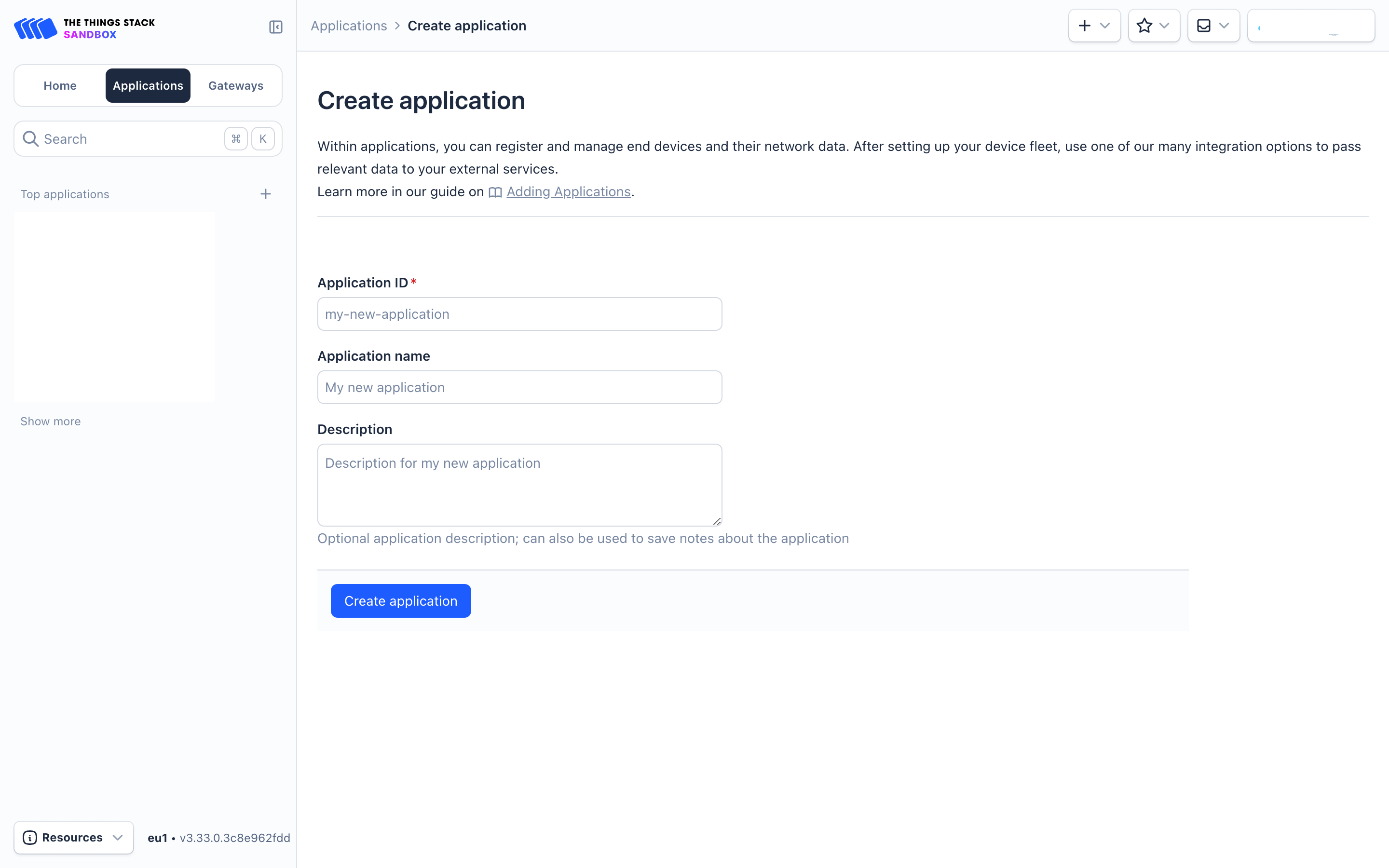
Sign up for a free account with The Things Stack Sandbox if you do not have one yet. Then, create an application as shown in the screenshots below.
Application ID: Provide a unique name to identify your application within The Things Stack, e.g., dragino-docs.
2.2.2 Adding manually
You can refer to the screenshots below to register your PF52 using The Things Stack's manual option.
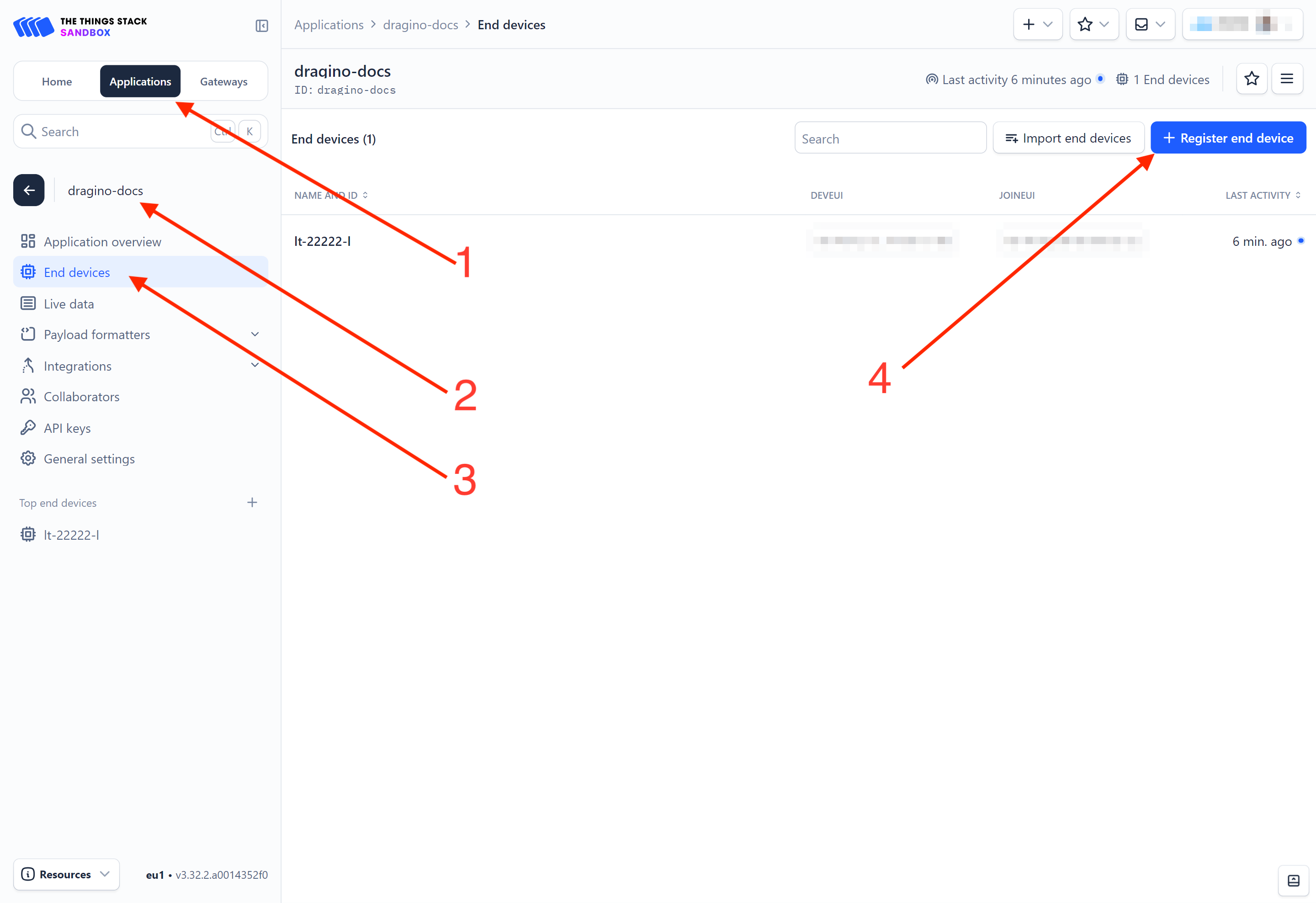
On The Things Stack console:
1. Click Applications.
2. Click <your application>. E.g. dragino-docs
3 Click End devices.
4. Click + Register end device button.
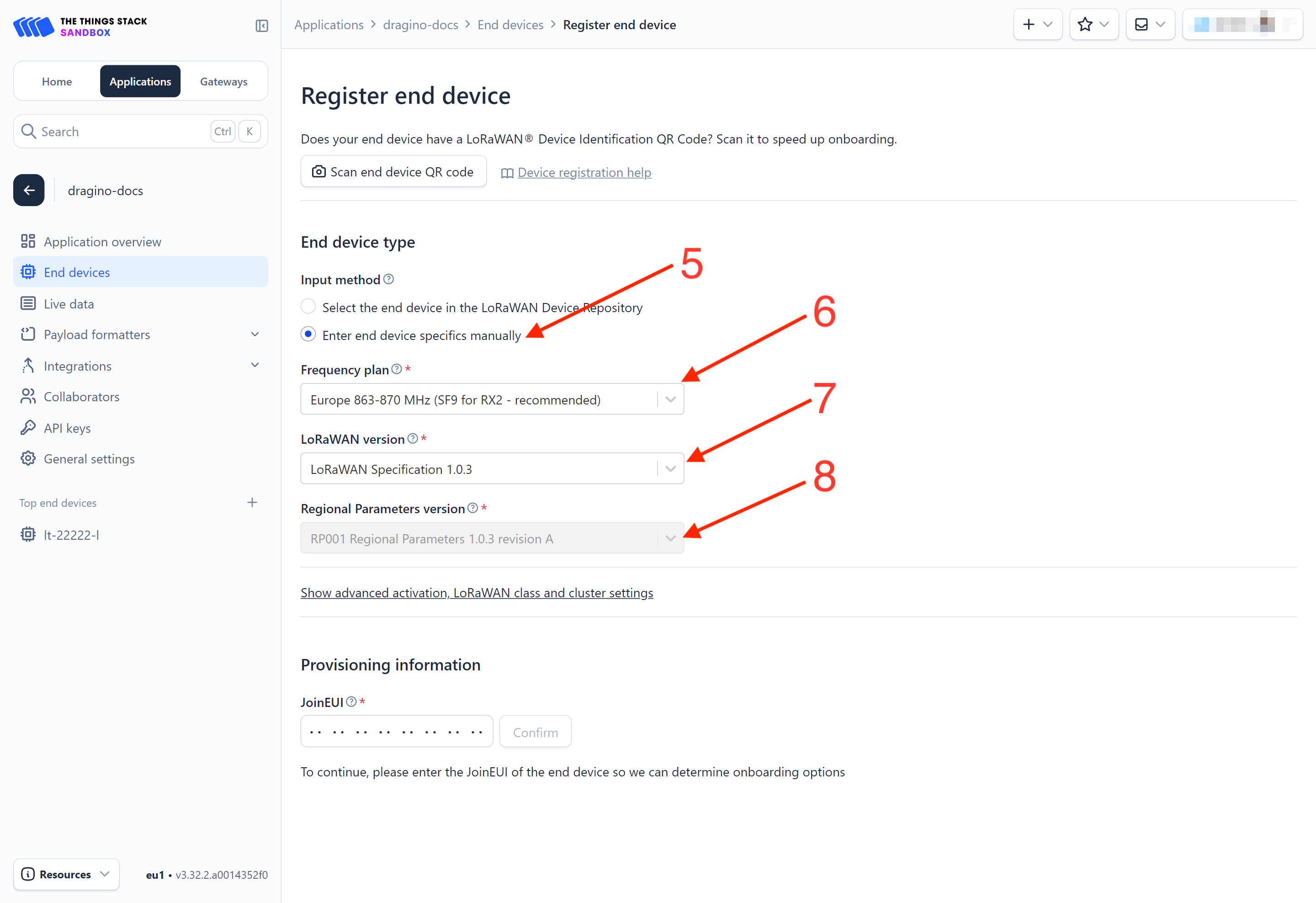
5. Select Enter end device specifies manually option.
-
Frequency plan: Select the frequency plan that matches your device. E.g.: Europe 863-870 MHz (SF9 for RX2 - recommended).
-
LoRaWAN version: LoRaWAN Specification 1.0.3
-
Regional Parameters version: You can't change it and it will select automatically.
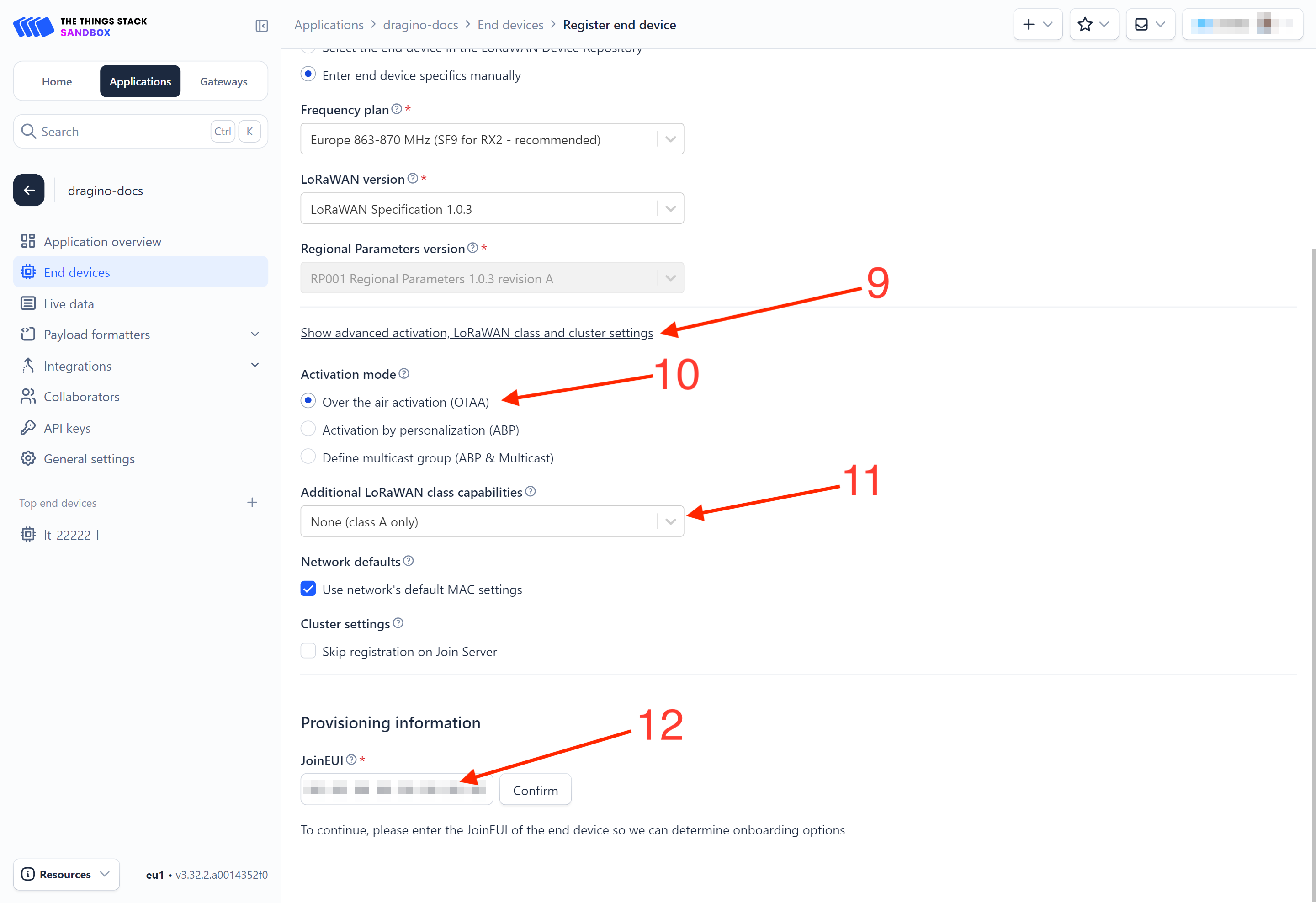
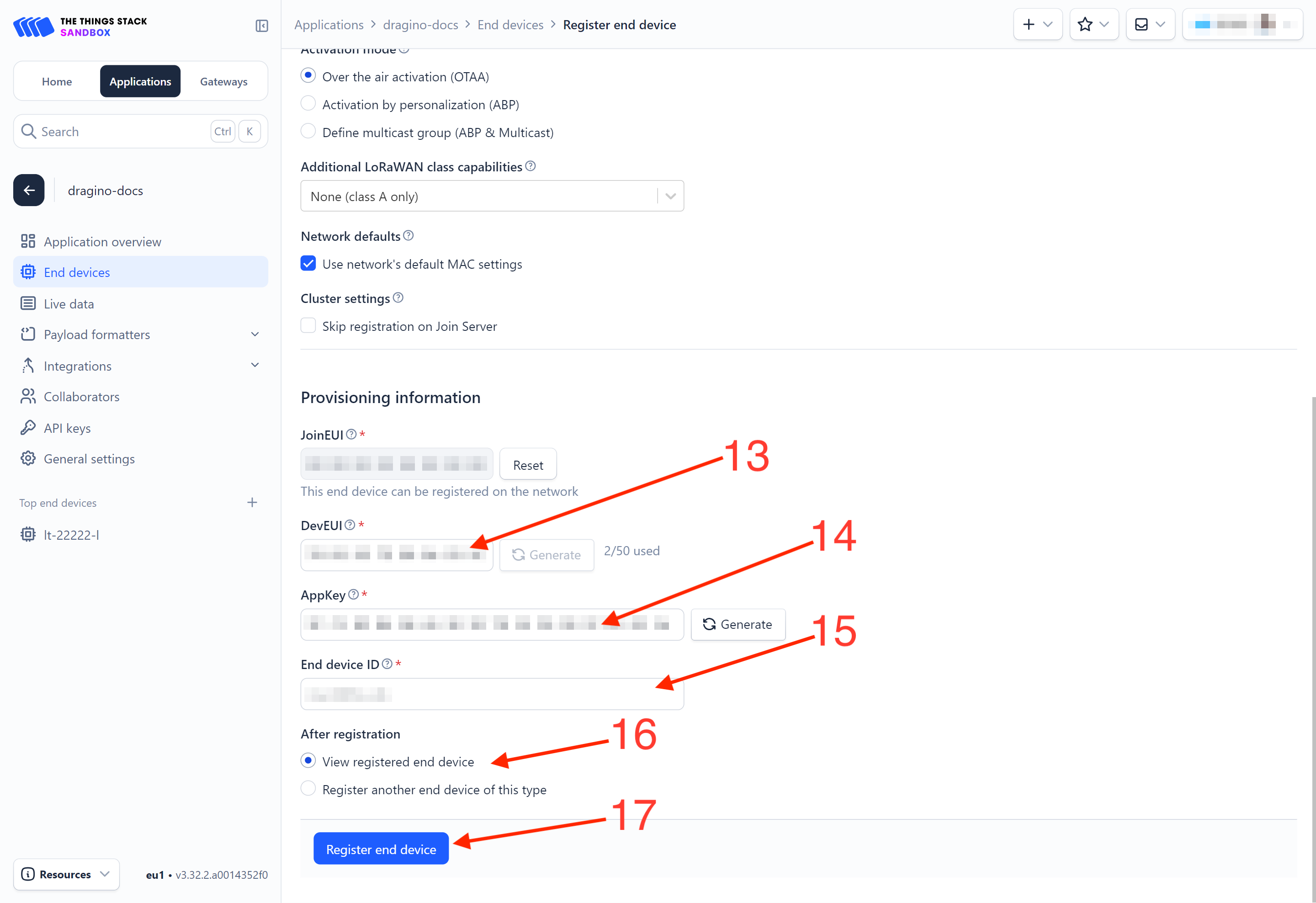
9. Click on the **Show advanced activation, LoRaWAN class and cluster settings **to expand the section.
10. Select Over the air activation (OTAA) option.
11. Select None (class A only).
- JoinEUI: Enter the AppEUI of the device (see the registration information sticker) and Click the Confirm button.
-
DevEUI: Enter the DevEUI of the device (see the registration information sticker).
-
AppKey: Enter the AppKey of the device (see the registration information sticker).
-
End device ID: Enter a name for your end device to uniquely identify it within this application.
16. Click View registered end device option.
17. Click Register end device button.
You will be navigated to the **Device overview **page.
2.2.3 Power on the PF52
Power on the PF52. It will then join The Things Stack. Once successfully connected, the device will begin uplinking sensor data to The Things Stack, which can be viewed on the Live data panel.
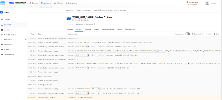
2.2.4 Uplink Decoder in The Things Stack
When the uplink payload arrives in The Things Stack, it is displayed in HEX format, which is not easy to read. You can add the PF52 decoder in The Things Stack for easier readability of each sensor reading.
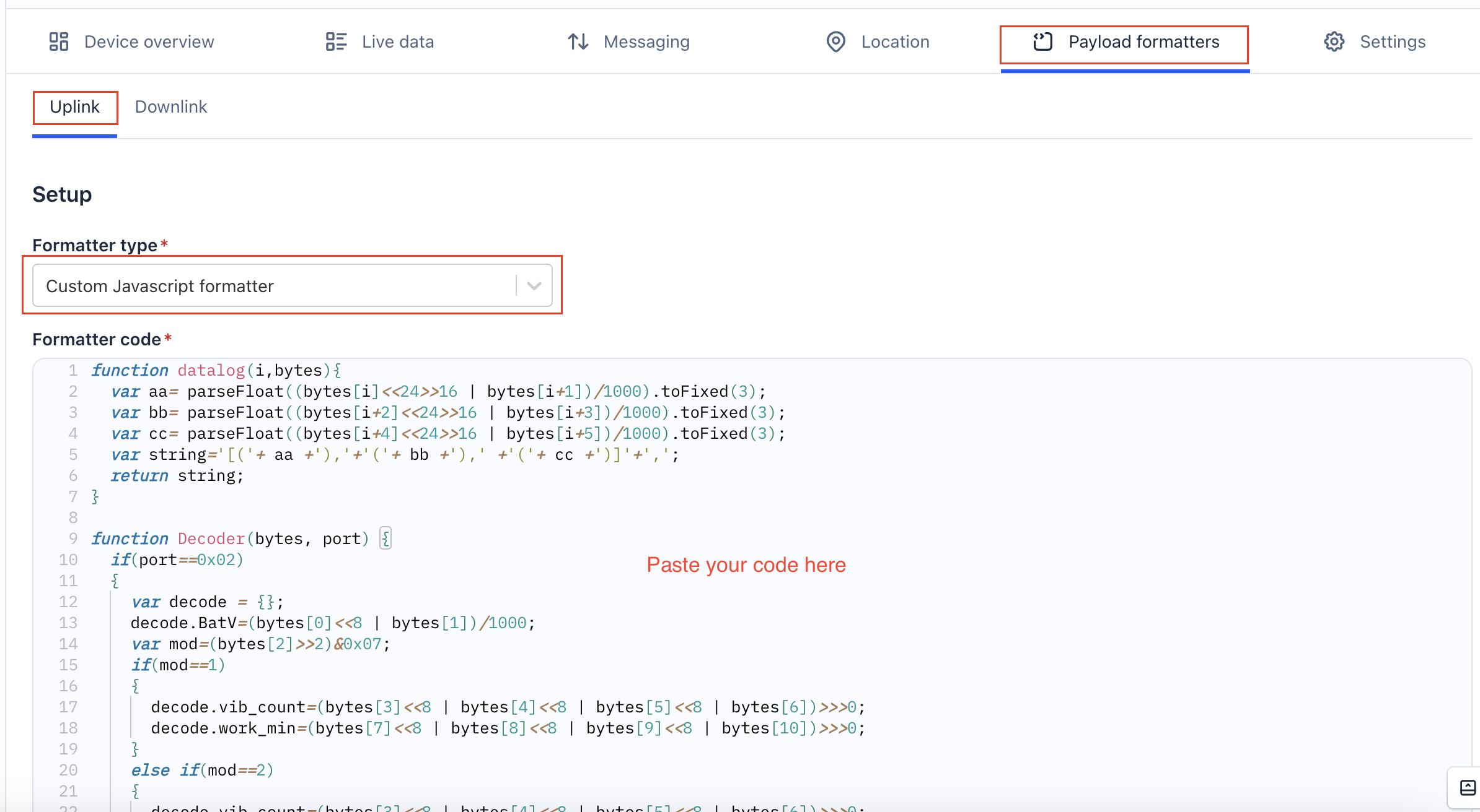
The uplink decoder can be added to the** Payload Formatters** of your device in The Things Stack. Refer to the screenshot below.
1. Click Uplink tab.
-
Formatter type: Select Custom Javascript formatter.
-
Formatter code: Copy the uplink payload formatter code from our dragino-end-node-decoder GitHub repository and paste it here.
4. Finally, click on the Save changes button.
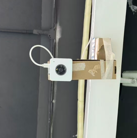
2.3 Installation method and usage
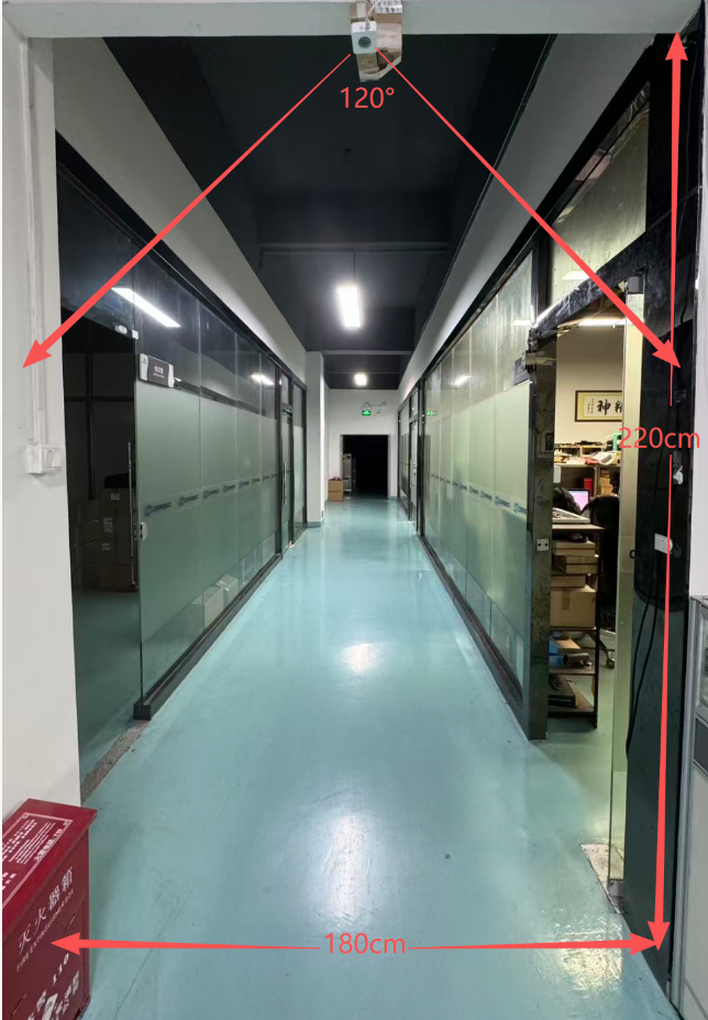
Mounting Height and Field of View
The PF52 has a mounting height limit of 220-250cm. Mounting it too high or too low will affect pedestrian detection and counting.
The recognition width is approximately 180cm. Because the camera's field of view is limited (approximately 120°), it relies on counting the number of people's heads passing by.
This width is calculated based on an average height of 170cm. For example, if your width is 200cm and your height is 170cm, your head will be lost in the camera's field of view when you pass from either side, and the camera will not be able to detect the person passing by.
2.3.1 Exit direction and entrance direction
The LED indicator lights are located in the upper left corner (front view). From left to right, they show the number of people entering (IN); from right to left, they show the number of people leaving (OUT).
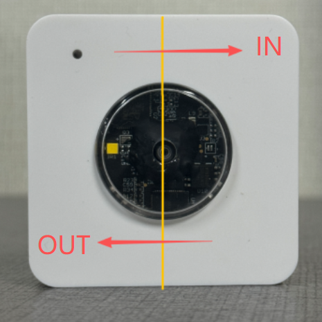
**IN: OUT: **
2.3.2 Bluetooth Transfer Screen
To effectively manage and monitor the PF52, users should first download the dedicated mobile application. This app enables remote control and real-time data synchronization with the device .
Before starting, ensure your smartphone’s Bluetooth is enabled and within effective range—typically within 10 meters without major obstructions to avoid signal interference .
Open the application and follow the in-app instructions to pair your smartphone with the PF52 device via Bluetooth.
Once paired successfully, the application will automatically detect the PF52 and begin synchronizing the device status. After connection is established, you can access real-time detection data and analysis results captured by the PF52 through the application .
Currently, only Android phones support the Bluetooth app function.
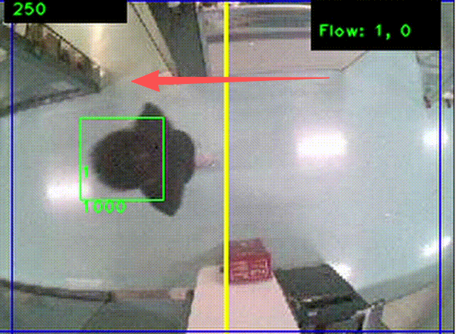
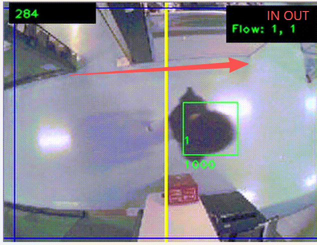
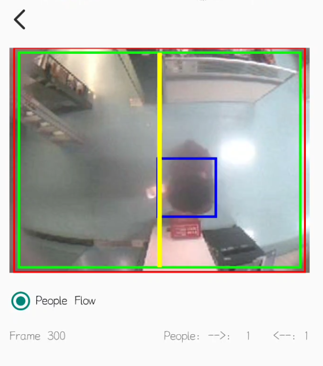
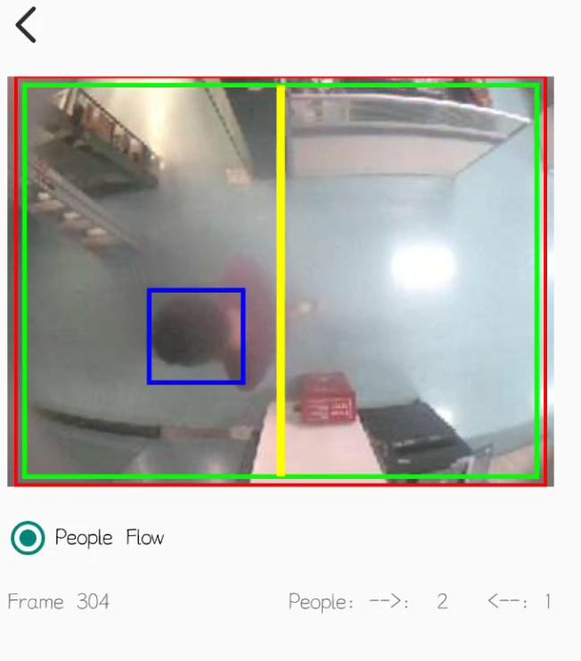
Bluetooth tool for pedestrian flow recognition:AlCameraTool
After opening the application, click "SCAN BLUETOOTH DEVICES", then click "NBee_SPPB1EAB1" to enter the screen.
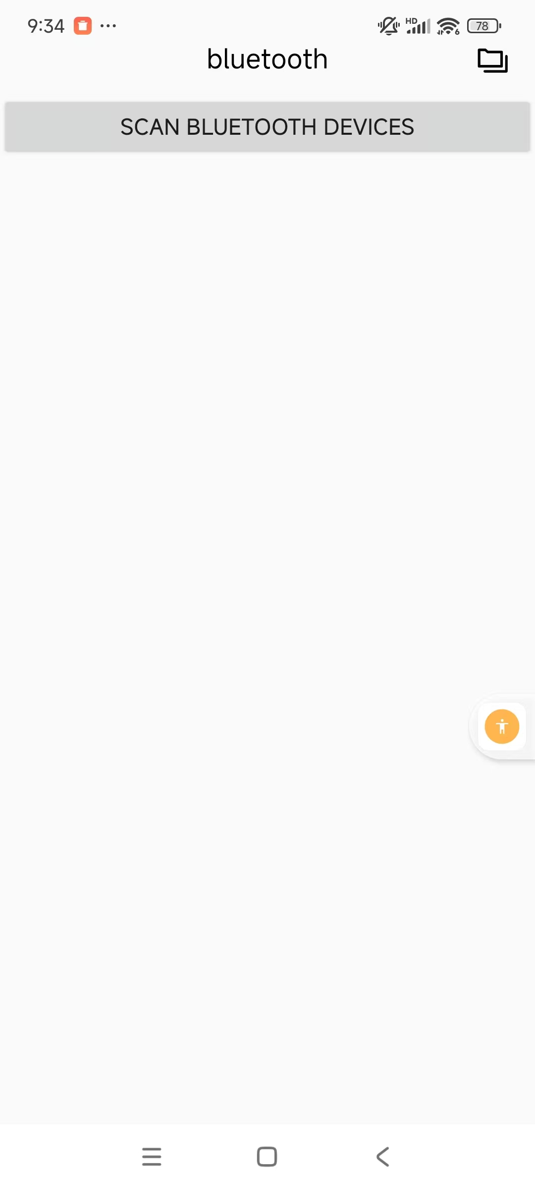

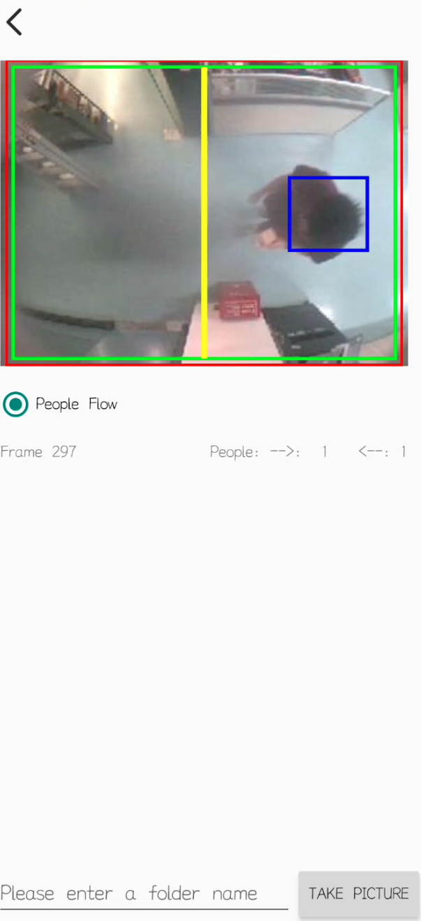
From the example, we can see that when a mobile phone is connected to PF52, it can observe the direction of a person and record data in real time.
2.4 Uplink Payload
Uplink payloads include two types: Valid Sensor Value and other status / control command.
- Valid Sensor Value: Use FPORT=2
- Other control command: Use FPORT other than 2.
2.4.1 Uplink FPORT=5, Device Status
Uplink the device configures with FPORT=5. Once PF52 Joined the network, it will uplink this message to the server. After first uplink, PF52 will uplink Device Status every 12 hours.
| **Size(bytes) ** | 1 | 2 | 1 | 1 | 2 |
|---|---|---|---|---|---|
| Value | Sensor Model | Firmware Version | Frequency Band | Sub-band | BAT |
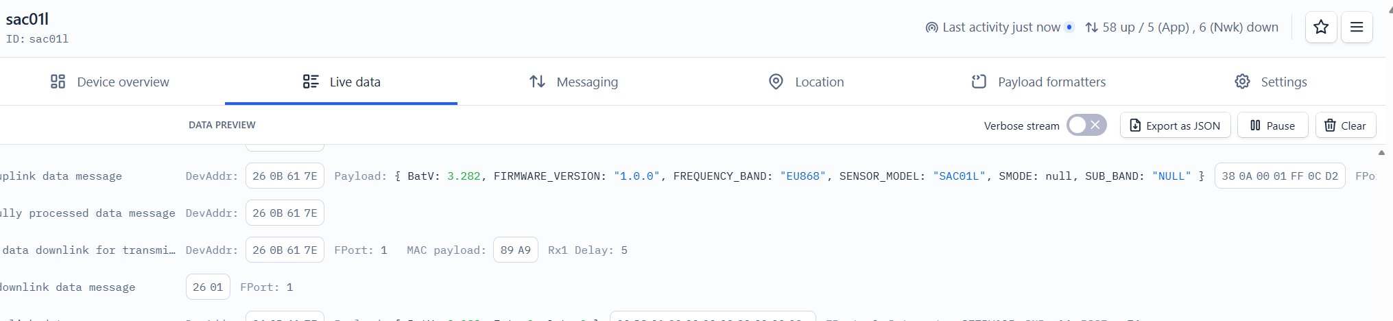
Example Payload (FPort=5): 38 0A 00 01 FF 0C D2
Sensor Model: For PF52, this value is 0x38.
Firmware Version: 0x0A00, Means: v1.0.0 version.
Frequency Band:
*0x01: EU868
*0x02: US915
*0x03: IN865
*0x04: AU915
*0x05: KZ865
*0x06: RU864
*0x07: AS923
*0x08: AS923-1
*0x09: AS923-2
*0x0a: AS923-3
Sub-Band: value 0x00 ~ 0x08(only for CN470, AU915,US915. Others are0x00)
BAT: shows the battery voltage for PF52.
Ex1: 0x0CD2 = 3282mV
Use can also get the Device Status uplink through the downlink command:
**Downlink: **0x2601
2.4.2 Uplink FPORT=2, Real time sensor value
PF52 will send this uplink after Device Status uplink once join LoRaWAN network successfully. And it will periodically send this uplink. Default interval is 20 minutes and can be changed.
Uplink uses FPORT=2 and every 20 minutes send one uplink by default.
| Size(bytes) | 2 | 1 | 4 | 4 | 4 |
|---|---|---|---|---|---|
| Value | BAT | MOD | sysTimeCurrent | OUT | INT |
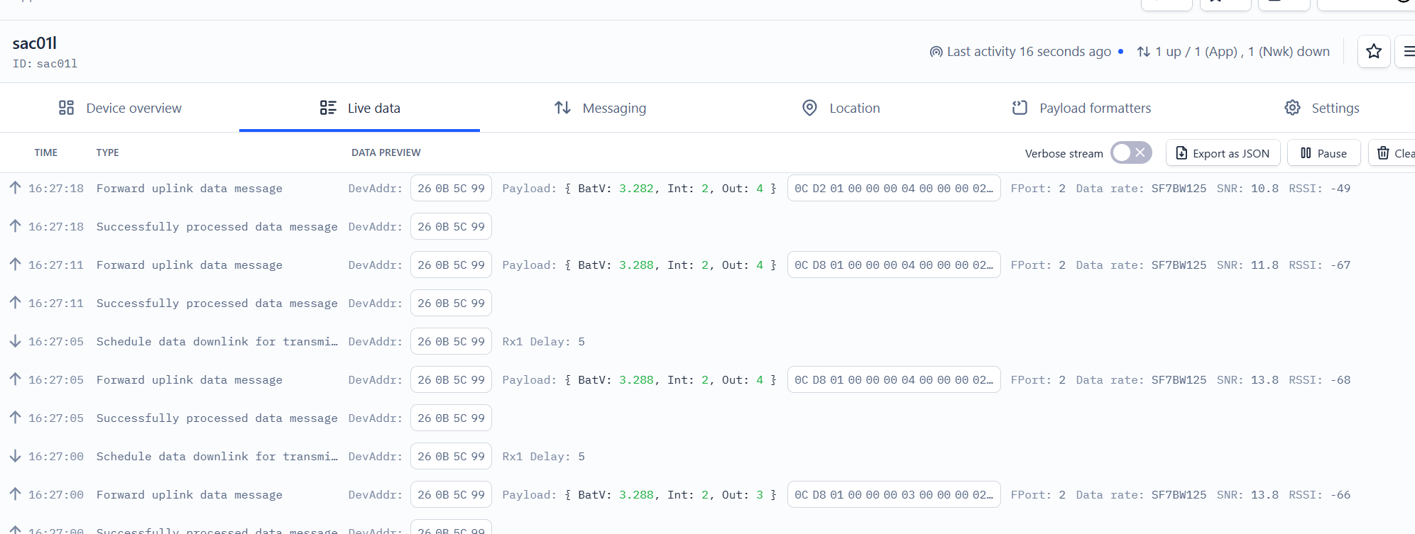
Example Payload (FPort=2): 0C D2 01 00 00 00 04 00 00 00 02
BAT:
- Example1: 0x0CD2/100=3.282
- Example2: 0xCD8/100=3.288
MOD:
- MOD: 0x01=1
sysTimeCurrent:
PF52 use Unix TimeStamp format based on:
Users can get this time from the link: https://www.epochconverter.com/ :
Below is the converter example.
Ex:66B5C1B0=2024-08-09 07:13:52
So, we can use AT+TIMESTAMP=1723187632 or downlink 66B5C1B0 to set the current time 2024 – August -- 9 Friday 07:13:52
OUT
- Example1: 0x00000004=4
INT
- Example1: 0x00000002=2
INT and OUT can be customized according to the situation, just swap the positions of INT and OUT in the decoder.
2.5 LED Indicator
The PF52 has a triple color LED which for easy showing different stage.
In a normal working state:
-
When the node is restarted, **BLUE **are sequentially lit.
-
During OTAA Join:
- For each Join Request uplink: the GREEN LED will blink once.
- Once Join Successful: the GREEN LED will be solid on for 5 seconds.
-
After joined, for each uplink, the BLUE LED or GREEN LED will blink once.
- BLUE LED when external sensor is connected
- GREEN LED when external sensor is not connected
2.6 Button
Press the button PF52 will reset and join network again.
3. Configure PF52 via AT command or LoRaWAN downlink
Use can configure PF52 via AT Command or LoRaWAN Downlink.
-
AT Command Connection: See FAQ.
-
LoRaWAN Downlink instruction for different platforms: IoT LoRaWAN Server
There are two kinds of commands to configure PF52, they are:
These commands are to configure:
-
General system settings like: uplink interval.
-
LoRaWAN protocol & radio-related commands.
They are the same for all Dragino Devices which supports DLWS-005 LoRaWAN Stack(Note**). These commands can be found on the wiki: End Device Downlink Command
- Commands special design for PF52
These commands are only valid for PF52, as below:
3.1 Downlink Command Set
| Command Example | Function | Response | Downlink |
|---|---|---|---|
| AT+TDC=? | View current TDC time | 1200000 OK | Default 1200000(ms) |
| AT+TDC=300000 | Set TDC time | OK | 0X0100012C: 01: fixed command 00012C: 0X00012C=300(seconds) |
| ATZ | Reset node | 0x04FF | |
| AT+FDR | Restore factory settings | 0X04FE | |
| AT+CFM=? | View the current confirmation mode status | 0 OK | Default 0 |
| AT+CFM=1 | Turn on confirmation mode | OK | 0x0500: close 0x0501: open 05: fixed command |
| AT+CHE=? | View the current sub-band select 0-7, the default is 0 | 0 OK | Default 0 |
| AT+CHE=2 | Set subband to 2 (CN470,US915,AU915) | Attention:Take effect after ATZ OK | 0X0702: 07: fixed command 02: Select subband 2 |
| AT+WMOD=? | View the current alarm mode status | 0 OK | Default 0 |
| AT+WMOD=1 | Turn on alarm mode | Attention:Take effect after ATZ OK | 0xA501: open 0XA500: close A5: fixed command |
| AT+CITEMP=? | View the current temperature detection time interval | 1 OK | Default 1(min) |
| AT+CITEMP=2 | Set the temperature detection time interval to 2min | OK | 0XA70002 A7: fixed command 0002: 0X0002=2(min) |
| AT+NJM=? | Check the current network connection method | 1 OK | Default 1 |
| AT+NJM=0 | Change the network connection method to ABP | Attention:Take effect after ATZ OK | 0X2000: ABP 0x2001: OTAA 20: fixed command |
| AT+RPL=? | View current RPL settings | 0 OK | Default 0 |
| AT+RPL=1 | set RPL=1 | OK | 0x2101: 21: fixed command 01: for details, check wiki |
| AT+ADR=? | View current ADR status | 1 OK | Default 0 |
| AT+ADR=0 | Set the ADR state to off | OK | 0x2200: close 0x2201: open 22: fixed command |
| AT+DR=? | View the current DR settings | OK | |
| AT+DR=1 | set DR to 1 It takes effect only when ADR=0 | OK | 0X22000100: 00: ADR=0 01: DR=1 00: TXP=0 22: fixed command |
| AT+TXP=? | View the current TXP | OK | |
| AT+TXP=0 | set TXP to 0 It takes effect only when ADR=0 | OK | 0X22000100: 00: ADR=0 01: DR=1 00: TXP=0 22: fixed command |
| Upload node configuration or DS18B20 ID | 0X2301:Upload node configuration 0x2302: Upload DS18B20 ID 23: fixed command | ||
| AT+DWELL=? | Check the high-rate upload settings | 1 OK | Default 1 |
| AT+DWELL=1 | Set high rate upload (AS923,AU915) | Attention:Take effect after ATZ OK | 0x2501: close 0x2500: open 25: fixed command for details, check wiki |
| AT+RJTDC=? | View current RJTDC set time | 20 OK | Default 20(min) |
| AT+RJTDC=10 | Set RJTDC time interval | OK | 0X26000A: 26: fixed command 000A: 0X000A=10(min) for details, check wiki |
| Retrieve stored data for a specified period of time | 0X3161DE7C7061DE8A800A: 31: fixed command 61DE7C70:0X61DE7C70=2022/1/12 15:00:00 61DE8A80:0X61DE8A80=2022/1/12 16:00:00 0A: 0X0A=10(second) View details 2.6.2 | ||
| AT+DDETECT=? | View the current DDETECT setting status and time | 0,1440 OK | Default 0,1440(min) |
| AT+DDETECT=1,1440,2880 | Set DDETECT setting status and time (When the node does not receive the downlink packet within the set time, it will re-enter the network) | OK | 0X320005A0: close 0X320105A0: open 32: fixed command 05A0: 0X05A0=1440(min) |
| Downlink Modification Alarm Mode (AT+WMOD,AT+CITEMP,AT+ARTEMP) | 0XAA010002000F00032: AA: fixed command 01: 0X01=1(AT+MOD) 0002: 0X0002=2(AT+CITEMP) 000F: 0X000F=15(AT+ARTEMP) 0032: 0X0032=50(AT+ARTEMP) |
3.2 Set Password
Feature: Set device password, max 9 digits.
AT Command: AT+PWORD
| Command Example | Function | Response |
|---|---|---|
| AT+PWORD=? | Show password | 123456 OK |
| AT+PWORD=999999 | Set password | OK |
Downlink Command:
No downlink command for this feature.
4. FAQ
4.1 AT Command and Downlink
Sending ATZ will reboot the node
Sending AT+FDR will restore the node to factory settings
Get the node's AT command setting by sending AT+CFG
Example:
AT+VER=EU868 v1.0
AT+NJM=1
AT+DEUI=25 32 12 45 65 26 12 35
AT+APPEUI=25 32 12 45 65 26 32 16
AT+APPKEY=25 32 12 45 65 26 32 16 89 48 85 65 45 87 89 55
AT+DADDR=00 00 00 00
AT+APPSKEY=00 00 00 00 00 00 00 00 00 00 00 00 00 00 00 00
AT+NWKSKEY=00 00 00 00 00 00 00 00 00 00 00 00 00 00 00 00
AT+NWKID=00 00 00 13
AT+ADR=1
AT+DR=5
AT+TXP=0
AT+CHS=0
AT+CLASS=A
AT+CFM=0
AT+JN1DL=5000
AT+JN2DL=6000
AT+RX1DL=5000
AT+RX2DL=6000
AT+RX1WTO=24
AT+RX2WTO=6
AT+RX2FQ=869525000
AT+RX2DR=0
AT+RPL=0
AT+FCU=6
AT+FCD=0
AT+CFS=0
AT+NJS=1
AT+DCS=0
AT+PNM=1
AT+PWORD=123456
AT+EXT=1
AT+TDC=120000
AT+TIMESTAMP=1640851037 2021 12 30 7 57 17
AT+RJTDC=20
AT+DDETECT=0,1440
AT+WMOD=0
AT+CITEMP=1
AT+ARTEMP=-40,125
4.2 How to upgrade the firmware?
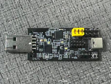
PF52 requires a program converter to upload images to PF52, which is used to upload image to PF52 for:
- Support new features
- For bug fix
- Change LoRaWAN bands.
Firmware and changelog can be downloaded from : Firmware download link
Methods to Update Firmware:
(Recommended way) OTA firmware update via wireless:UART Access for LoRa ST v4 base model - DRAGINO
To upgrade the firmware, connect the TXD, RXD.
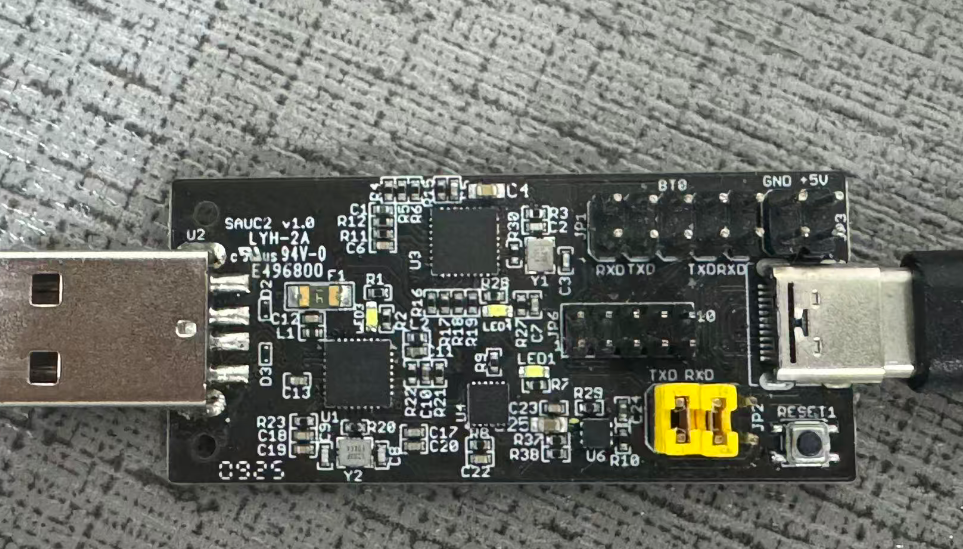
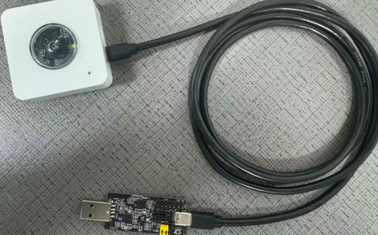
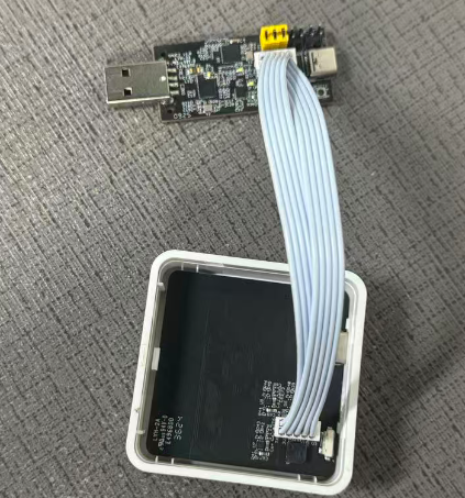
The method for upgrading IMG files is as follows:
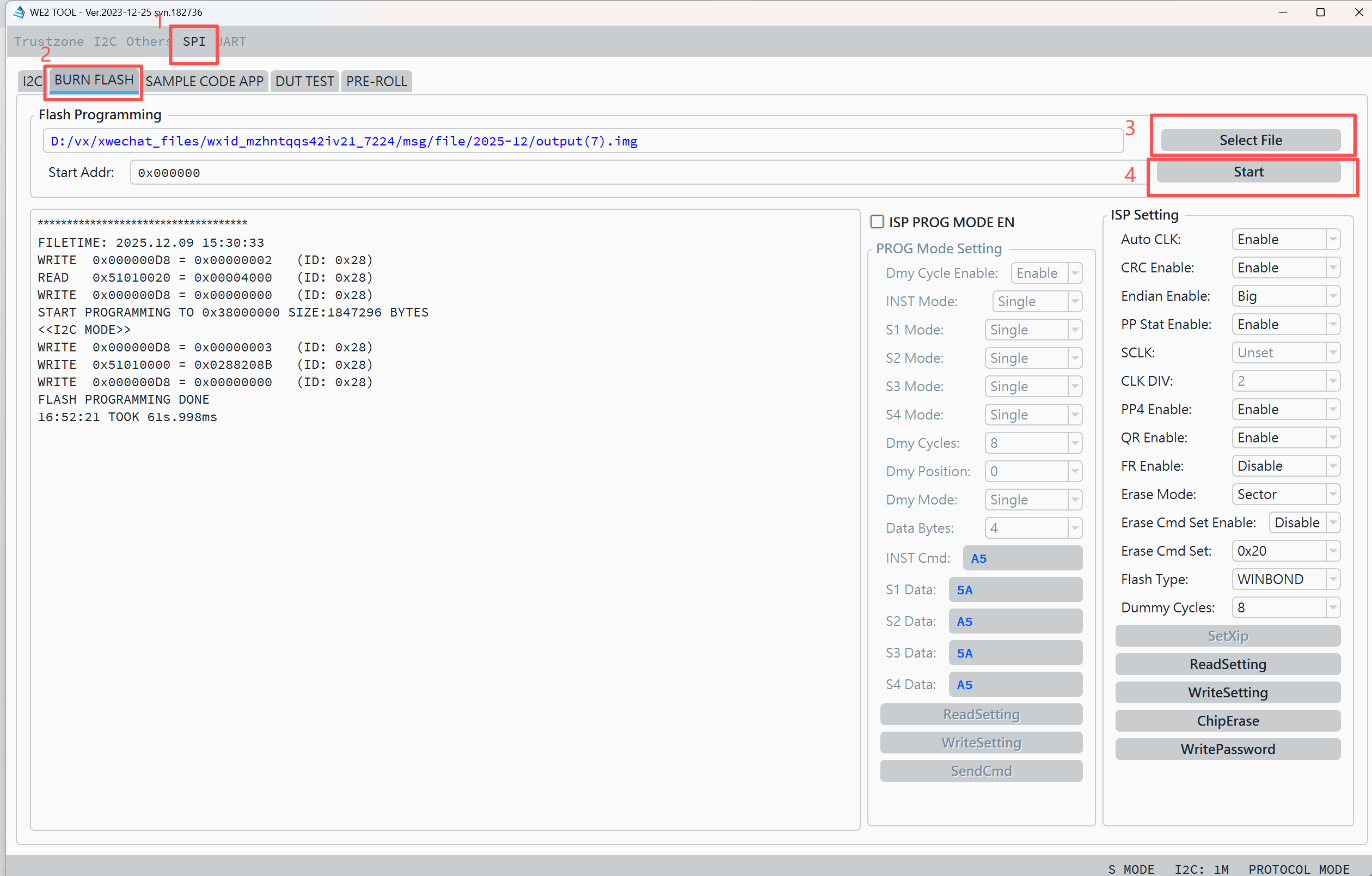
Connect the contacts and data cable as shown in the diagram below, then connect to the PC and open the we2_demo_tool host computer to burn the img file.
1. Select ISP.
2. Select BURN FLASH.
3. Select the img file to be burned.
4. Click to burn.
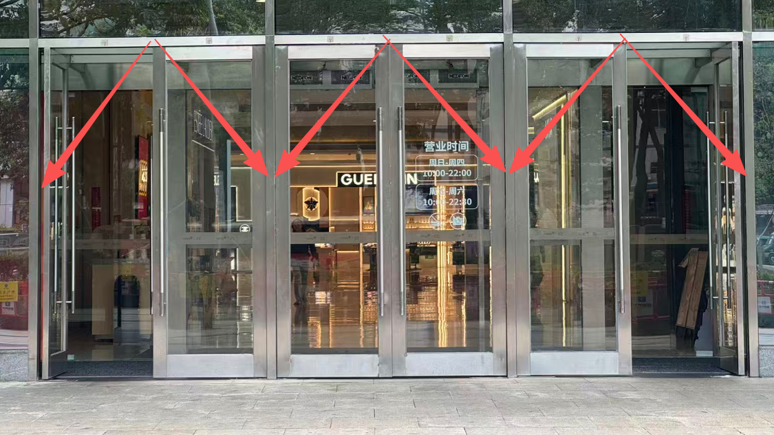
4.3 Installed at the entrance of large shopping mall
If you encounter a large shopping mall entrance where the following method is installed, it is recommended to use a spaced approach, placing a sensor above each of the three entrances to calculate the number of people.
5. Order Info
5.1 Main Device
Part Number: PF52-XX
**XX **: The default frequency band
- **AS923: **LoRaWAN AS923 band
- **AU915: **LoRaWAN AU915 band
- **EU433: **LoRaWAN EU433 band
- EU868: LoRaWAN EU868 band
- **KR920: **LoRaWAN KR920 band
- **US915: **LoRaWAN US915 band
- **IN865: **LoRaWAN IN865 band
- **CN470: **LoRaWAN CN470 band
6. Packing Info
Package Includes:
- PF52 - People Counting Sensor x 1
Dimension and weight:
- Package Size/ pcs: 155*145*60 mm
- Weight/ pcs: 280g
7. Support
- Support is provided Monday to Friday, from 09:00 to 18:00 GMT+8. Due to different timezones we cannot offer live support. However, your questions will be answered as soon as possible in the before-mentioned schedule.
- Provide as much information as possible regarding your enquiry (product models, accurately describe your problem and steps to replicate it etc) and send a mail to support@dragino.com.
8. FCC Warning
This device complies with part 15 of the FCC Rules.Operation is subject to the following two conditions:
(1) This device may not cause harmful interference;
(2) this device must accept any interference received,including interference that may cause undesired operation.
9. Appendix I:According to the use
Installed in the middle of the aisle threshold, it can detect the entire aisle to avoid omissions.
Installation height limit 2.2m-2.5m.
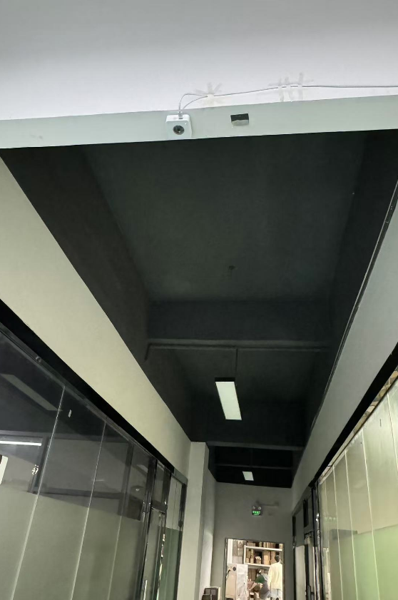
When pedestrians pass by, the image can be viewed through the BLE app.
0