AI52
1. Introduction
1.1 What is AI52 pedestrian recognition Sensor
Dragino AI52 is a long-range LoRaWAN sensor that can autonomously transmit to yolo8n model. It includes a built-in AI camera sensor and has a USB Type-C
AI52 Identify and count the objects you trained. and send these values via long-range wireless LoRaWAN protocol. It targets professional wireless sensor network applications such as smart metering, smart cities, and so on.
AI52 uses an external power supply and can work for a long time.
AI52 is fully compatible with LoRaWAN v1.0.3 protocol, it can work with standard LoRaWAN gateway.
AI52 supports Datalog feature to make sure users won't miss sensor data. It records sensor value for every uplink. These values can be retrieved by LoRaWAN server via downlink command.
1.2 Features
- LoRaWAN v1.0.3 Class A protocol.
- Low power consumption
- AI Image Sensor.
- Send image to IoT server
- Frequency Bands: CN470/EU433/KR920/US915/EU868/AS923/AU915
- Support Interrupt uplink
- Support Bluetooth v5.1 and LoRaWAN remote configure
- Support wireless OTA update firmware
- AT Commands to change parameters
- Uplink on periodically
- Downlink to change configure
- IP Rating: IP52
1.3 Specification
Common DC Characteristics:
- DC power supply 5v
- Operating Temperature: -40 ~ 85°C
Camera:
- Mono: black & white
- Angle: 110°
- Image size:64kb
- Image resolution:640x480
- Power Consumption: 206.1mW
- Supply Voltage: DC5V
- Idel Mode: 6uA
- Take Photo: 41.22 mA and 3171 ms
- Cable Length:150cm
- Dimension:46.2x29x13.8 mm
- Waterproof level:IP52
LoRa Spec:
- Frequency Range, Band 1 (HF): 862 ~ 1020 Mhz
- Max +22 dBm constant RF output vs.
- RX sensitivity: down to -139 dBm.
- Excellent blocking immunity
1.5 Storage & Operation Temperature
-10 ~ 50 °C or -40 ~ 60 °C
1.6 Applications
- Smart Buildings & Home Automation
- Logistics and Supply Chain Management
- Smart Metering
- Smart Agriculture
- Smart Cities
- Smart Factory
2. Configure AI52 to connect to LoRaWAN network
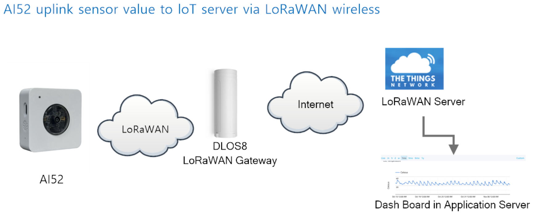
2.1 How it works
The AI52 is configured as LoRaWAN OTAA Class A mode by default. It has OTAA keys to join LoRaWAN network. To connect a local LoRaWAN network, you need to input the OTAA keys in the LoRaWAN IoT server and press the button to activate the AI52. It will automatically join the network via OTAA and start to send the sensor value. The default uplink interval is 20 minutes.
The LED light is at the upper left for a positive viewing angle.When the character crosses the horizontal line in the middle, the count increases by one.
For details, please see the case.
2.2 Example to join LoRaWAN network
This section shows an example for how to join the TheThingsNetwork LoRaWAN IoT server. Usages with other LoRaWAN IoT servers are of similar procedure.

Assume the DLOS8 is already set to connect to TTN V3 network . We need to add the AI52 device in TTN V3 portal.
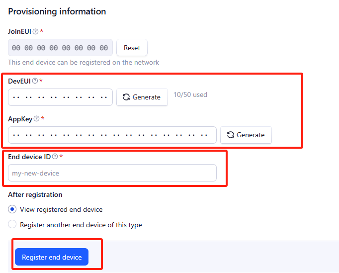
Step 1: Create a device in TTN V3 with the OTAA keys from AI52.
Each AI52 is shipped with a sticker with the default DEV EUI as below:
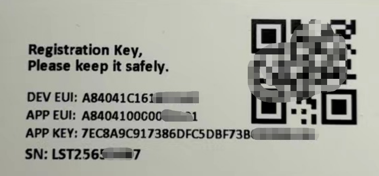
Enter these keys in the LoRaWAN Server portal. Below is TTN V3 screen shot:
Create the application.
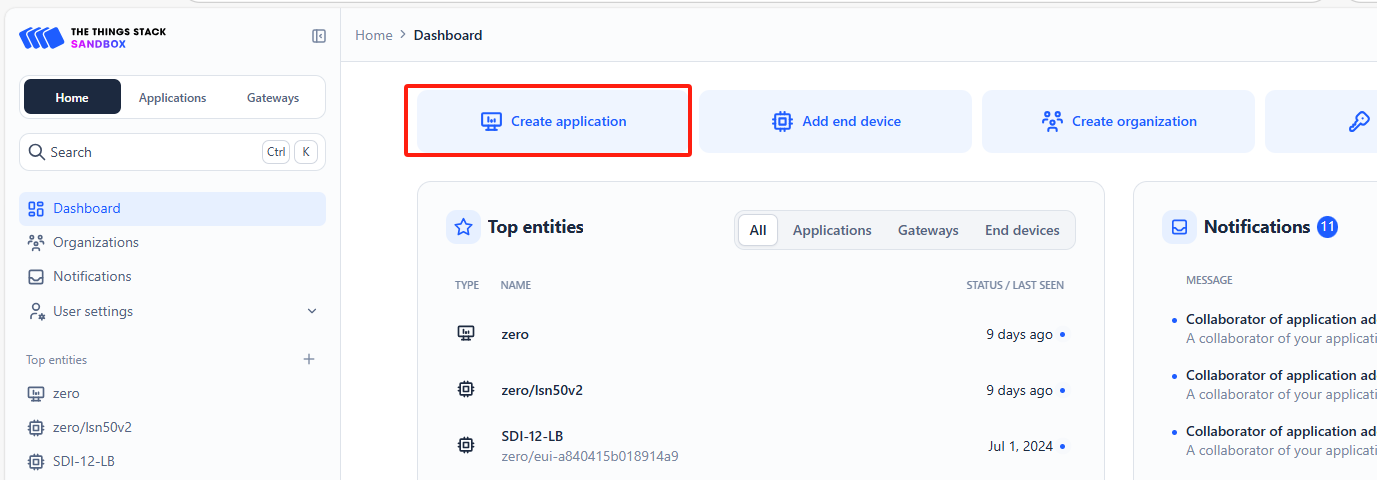
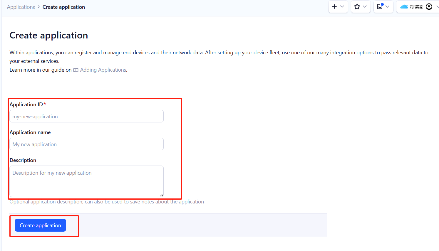
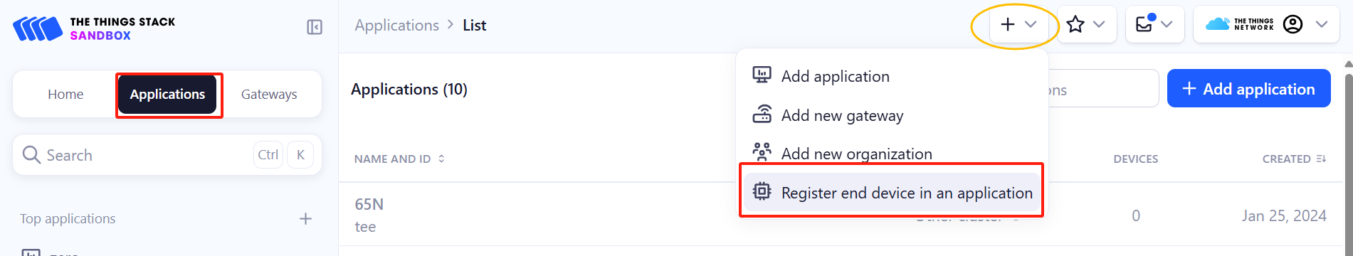
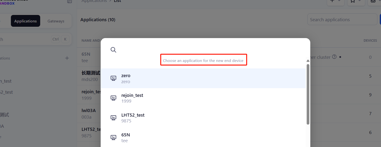
Add devices to the created Application.
Enter end device specifics manually.
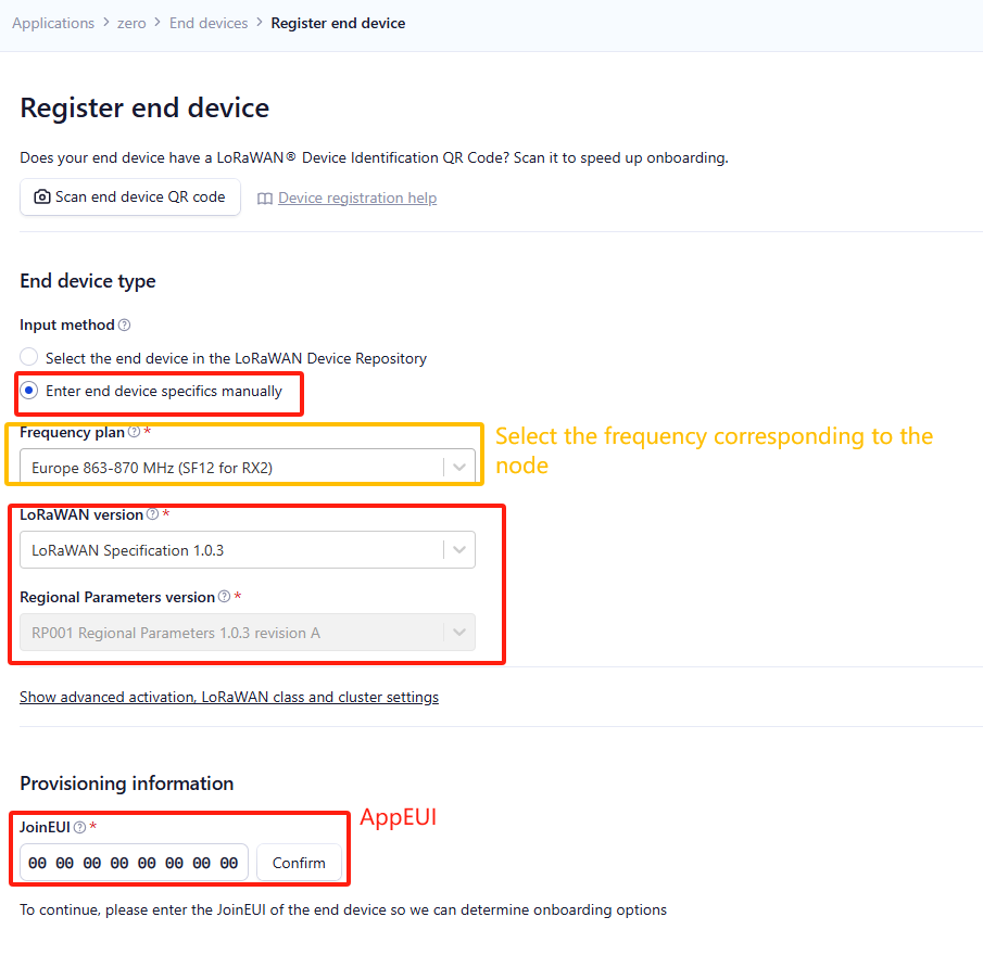
Add DevEUI and AppKey.
Customize a platform ID for the device.
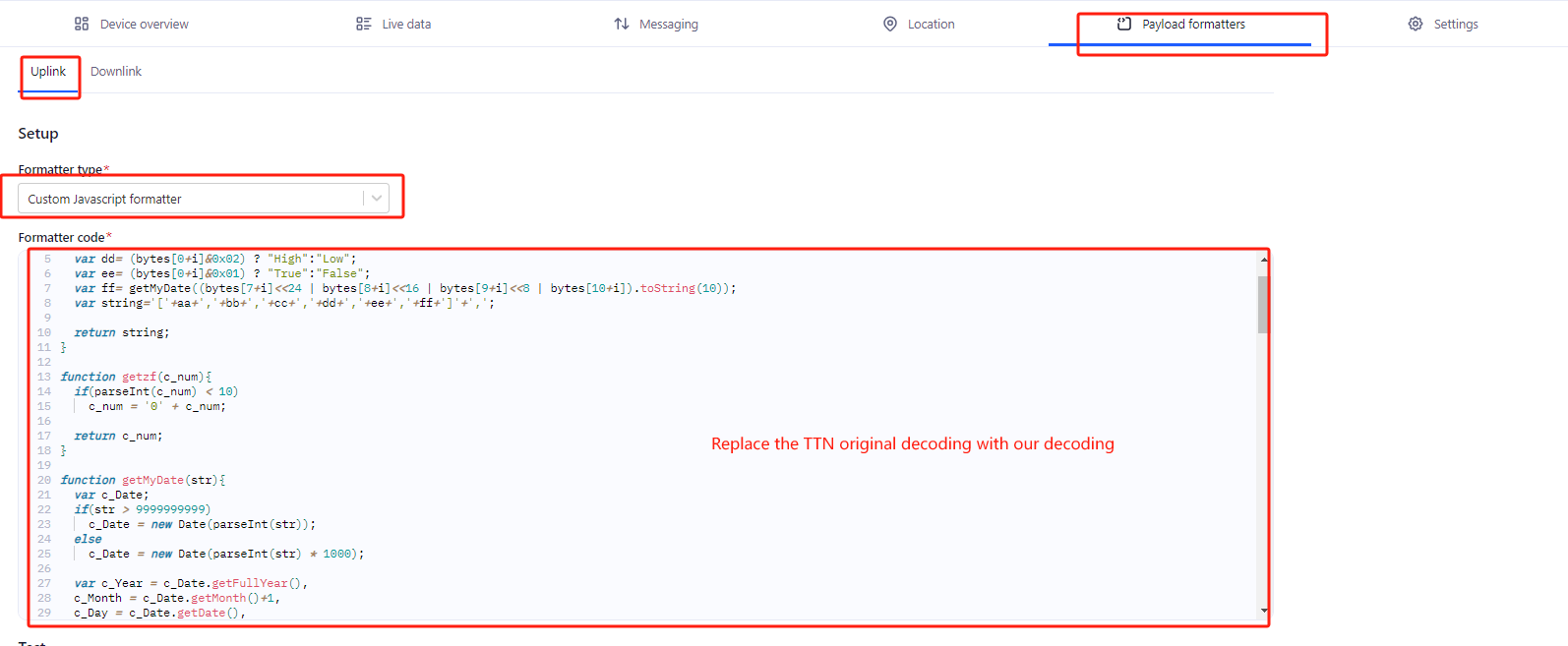
Step 2: Add decoder.
In TTN, user can add a custom payload so it shows friendly reading.
Click this link to get the decoder: https://github.com/dragino/dragino-end-node-decoder/tree/main/
Below is TTN screen shot:
Step 3: Activate on AI52
Press the ACT button for more than 3 seconds to activate AI52.
Green led will fast blink 5 times, device will enter OTA mode for 3 seconds. And then start to JOIN LoRaWAN network. Green led will solidly turn on for 5 seconds after joined in network.
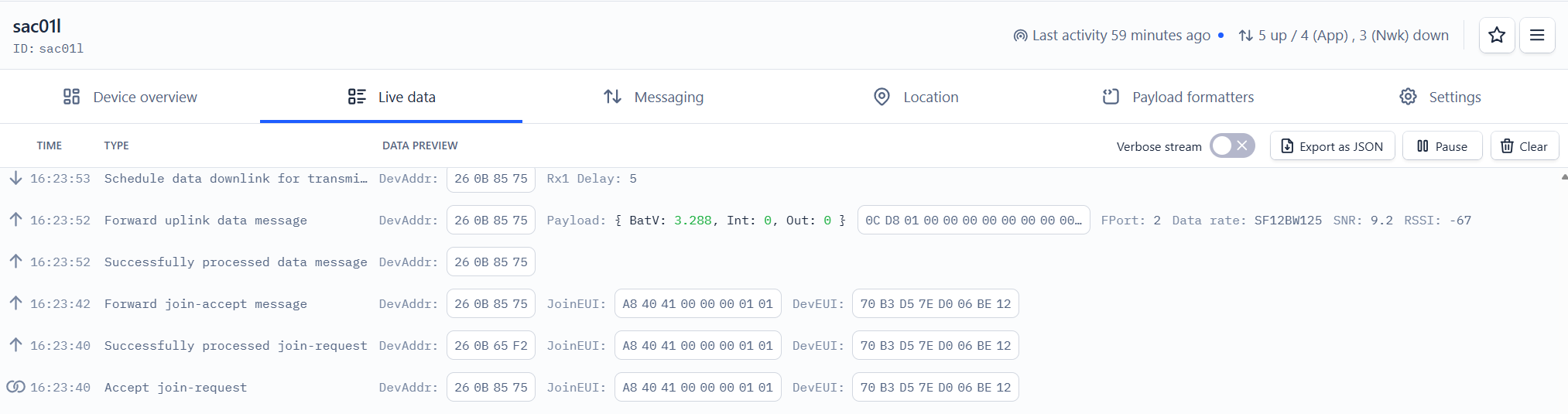
After join success, it will start to upload messages to TTN V3 and you can see the messages in the panel.
2.3 Uplink Payload
Uplink payloads include two types: Valid Sensor Value and other status / control command.
- Valid Sensor Value: Use FPORT=2
- Other control command: Use FPORT other than 2.
2.3.1 Uplink FPORT=5, Device Status
Uplink the device configures with FPORT=5. Once PF52 Joined the network, it will uplink this message to the server. After first uplink, PF52 will uplink Device Status every 12 hours.
| Size(bytes) | 1 | 2 | 1 | 1 | 2 |
|---|---|---|---|---|---|
| Value | Sensor Model | Firmware Version | Frequency Band | Sub-band | BAT |
Example Payload (FPort=5): 38 0A 00 01 FF 0C D2
Sensor Model: For PF52, this value is 0x38.
Firmware Version: 0x0A00, Means: v1.0.0 version.
Frequency Band:
*0x01: EU868
*0x02: US915
*0x03: IN865
*0x04: AU915
*0x05: KZ865
*0x06: RU864
*0x07: AS923
*0x08: AS923-1
*0x09: AS923-2
*0x0a: AS923-3
Sub-Band: value 0x00 ~ 0x08(only for CN470, AU915,US915. Others are0x00)
BAT: shows the battery voltage for PF52.
Ex1: 0x0CD2 = 3282mV
Use can also get the Device Status uplink through the downlink command:
Downlink: 0x2601
2.3.3 Decoder in TTN V3
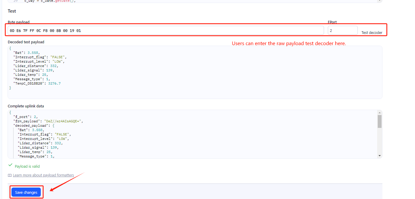
In LoRaWAN protocol, the uplink payload is HEX format, user need to add a payload formatter/decoder in LoRaWAN Server to get human friendly string.
In TTN , add formatter as below:
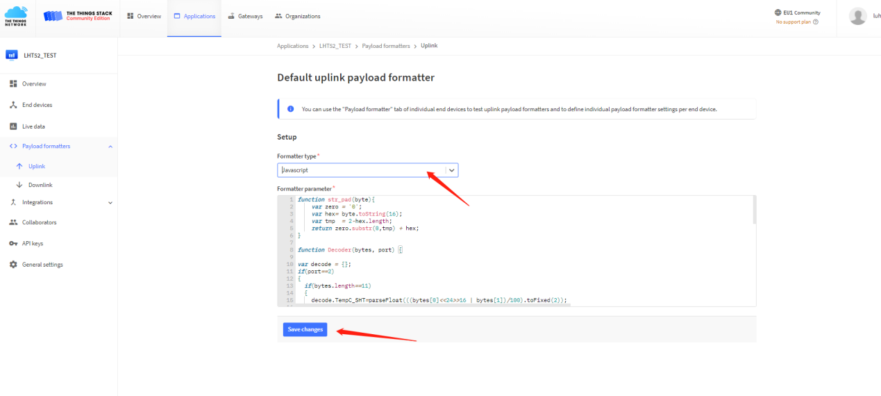
Please check the decoder from this link:
2.5 LED Indicator
The PF52 has a triple color LED which for easy showing different stage.
In a normal working state:
-
When the node is restarted, BLUE are sequentially lit.
-
During OTAA Join:
- For each Join Request uplink: the GREEN LED will blink once.
- Once Join Successful: the GREEN LED will be solid on for 5 seconds.
-
After joined, for each uplink, the BLUE LED or GREEN LED will blink once.
- BLUE LED when external sensor is connected
- GREEN LED when external sensor is not connected
2.6 Button
Press the button PF52 will reset and join network again.
2.7 Bluetooth Transfer Screen
To better manage and monitor PF52 devices, users can remotely control and manage the devices by downloading a specially designed mobile application.
Once the application is installed, the next step is to establish a Bluetooth connection between your smart device and PF52.
Please make sure that the Bluetooth function of your mobile phone is turned on and within the search range of the device (usually within 10 meters).
After opening the application, follow the on-screen prompts to complete the simple pairing process.
After a successful connection, the application will automatically detect the PF52 and start synchronizing the device status.
Once the connection is established, users can obtain high-definition real-time images captured by PF52 through the application.
From the example, we can see that when a mobile phone is connected to PF52, it can observe the direction of a person and record data in real time.
3. Configure PF52 via AT command or LoRaWAN downlink
Use can configure PF52 via AT Command or LoRaWAN Downlink.
- AT Command Connection: See FAQ.
- LoRaWAN Downlink instruction for different platforms: IoT LoRaWAN Server
There are two kinds of commands to configure PF52, they are:
These commands are to configure:
- General system settings like: uplink interval.
- LoRaWAN protocol & radio-related commands.
They are the same for all Dragino Devices which supports DLWS-005 LoRaWAN Stack(Note**). These commands can be found on the wiki: End Device Downlink Command
- Commands special design for PF52
These commands are only valid for PF52, as below:
3.1 Downlink Command Set
| Command Example | Function | Response | Downlink |
|---|---|---|---|
| AT+TDC=? | View current TDC time | 1200000 OK | Default 1200000(ms) |
| AT+TDC=300000 | Set TDC time | OK | 0X0100012C: 01: fixed command 00012C: 0X00012C=300(seconds) |
| ATZ | Reset node | 0x04FF | |
| AT+FDR | Restore factory settings | 0X04FE | |
| AT+CFM=? | View the current confirmation mode status | 0 OK | Default 0 |
| AT+CFM=1 | Turn on confirmation mode | OK | 0x0500: close 0x0501: open 05: fixed command |
| AT+CHE=? | View the current sub-band select 0-7, the default is 0 | 0 OK | Default 0 |
| AT+CHE=2 | Set subband to 2 (CN470,US915,AU915) | Attention:Take effect after ATZ OK | 0X0702: 07: fixed command 02: Select subband 2 |
| AT+WMOD=? | View the current alarm mode status | 0 OK | Default 0 |
| AT+WMOD=1 | Turn on alarm mode | Attention:Take effect after ATZ OK | 0xA501: open 0XA500: close A5: fixed command |
| AT+CITEMP=? | View the current temperature detection time interval | 1 OK | Default 1(min) |
| AT+CITEMP=2 | Set the temperature detection time interval to 2min | OK | 0XA70002 A7: fixed command 0002: 0X0002=2(min) |
| AT+NJM=? | Check the current network connection method | 1 OK | Default 1 |
| AT+NJM=0 | Change the network connection method to ABP | Attention:Take effect after ATZ OK | 0X2000: ABP 0x2001: OTAA 20: fixed command |
| AT+RPL=? | View current RPL settings | 0 OK | Default 0 |
| AT+RPL=1 | set RPL=1 | OK | 0x2101: 21: fixed command 01: for details, check wiki |
| AT+ADR=? | View current ADR status | 1 OK | Default 0 |
| AT+ADR=0 | Set the ADR state to off | OK | 0x2200: close 0x2201: open 22: fixed command |
| AT+DR=? | View the current DR settings | OK | |
| AT+DR=1 | set DR to 1 It takes effect only when ADR=0 | OK | 0X22000100: 00: ADR=0 01: DR=1 00: TXP=0 22: fixed command |
| AT+TXP=? | View the current TXP | OK | |
| AT+TXP=0 | set TXP to 0 It takes effect only when ADR=0 | OK | 0X22000100: 00: ADR=0 01: DR=1 00: TXP=0 22: fixed command |
| Upload node configuration or DS18B20 ID | 0X2301:Upload node configuration 0x2302: Upload DS18B20 ID 23: fixed command | ||
| AT+DWELL=? | Check the high-rate upload settings | 1 OK | Default 1 |
| AT+DWELL=1 | Set high rate upload (AS923,AU915) | Attention:Take effect after ATZ OK | 0x2501: close 0x2500: open 25: fixed command for details, check wiki |
| AT+RJTDC=? | View current RJTDC set time | 20 OK | Default 20(min) |
| AT+RJTDC=10 | Set RJTDC time interval | OK | 0X26000A: 26: fixed command 000A: 0X000A=10(min) for details, check wiki |
| Retrieve stored data for a specified period of time | 0X3161DE7C7061DE8A800A: 31: fixed command 61DE7C70:0X61DE7C70=2022/1/12 15:00:00 61DE8A80:0X61DE8A80=2022/1/12 16:00:00 0A: 0X0A=10(second) View details 2.6.2 | ||
| AT+DDETECT=? | View the current DDETECT setting status and time | 0,1440 OK | Default 0,1440(min) |
| AT+DDETECT=1,1440,2880 | Set DDETECT setting status and time (When the node does not receive the downlink packet within the set time, it will re-enter the network) | OK | 0X320005A0: close 0X320105A0: open 32: fixed command 05A0: 0X05A0=1440(min) |
| Downlink Modification Alarm Mode (AT+WMOD,AT+CITEMP,AT+ARTEMP) | 0XAA010002000F00032: AA: fixed command 01: 0X01=1(AT+MOD) 0002: 0X0002=2(AT+CITEMP) 000F: 0X000F=15(AT+ARTEMP) 0032: 0X0032=50(AT+ARTEMP) |
3.2 Set Password
Feature: Set device password, max 9 digits.
AT Command: AT+PWORD
| Command Example | Function | Response |
|---|---|---|
| AT+PWORD=? | Show password | 123456 OK |
| AT+PWORD=999999 | Set password | OK |
Downlink Command:
No downlink command for this feature.
4. FAQ
4.1 AT Command and Downlink
Sending ATZ will reboot the node
Sending AT+FDR will restore the node to factory settings
Get the node's AT command setting by sending AT+CFG
Example:
AT+VER=EU868 v1.0
AT+NJM=1
AT+DEUI=25 32 12 45 65 26 12 35
AT+APPEUI=25 32 12 45 65 26 32 16
AT+APPKEY=25 32 12 45 65 26 32 16 89 48 85 65 45 87 89 55
AT+DADDR=00 00 00 00
AT+APPSKEY=00 00 00 00 00 00 00 00 00 00 00 00 00 00 00 00
AT+NWKSKEY=00 00 00 00 00 00 00 00 00 00 00 00 00 00 00 00
AT+NWKID=00 00 00 13
AT+ADR=1
AT+DR=5
AT+TXP=0
AT+CHS=0
AT+CLASS=A
AT+CFM=0
AT+JN1DL=5000
AT+JN2DL=6000
AT+RX1DL=5000
AT+RX2DL=6000
AT+RX1WTO=24
AT+RX2WTO=6
AT+RX2FQ=869525000
AT+RX2DR=0
AT+RPL=0
AT+FCU=6
AT+FCD=0
AT+CFS=0
AT+NJS=1
AT+DCS=0
AT+PNM=1
AT+PWORD=123456
AT+EXT=1
AT+TDC=120000
AT+TIMESTAMP=1640851037 2021 12 30 7 57 17
AT+RJTDC=20
AT+DDETECT=0,1440
AT+WMOD=0
AT+CITEMP=1
AT+ARTEMP=-40,125
4.2 How to upgrade the firmware?
AI52 requires a program converter to upload images to AI52, which is used to upload image to AI52 for:
- Support new features
- For bug fix
- Change LoRaWAN bands.
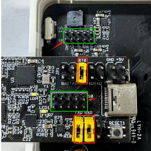
Update through UART TTL interface: Instruction
To upgrade the firmware, connect the TXD, RXD, and BTO pins next to the reset button. Connect the Dupont cable to the USB board and AI52 correctly, with pin 10 corresponding to pin 10.
2.Train the model and import it into the application
The following uses a chip recognition as an example, and the data is sent based on the number of chips recognized under the camera.
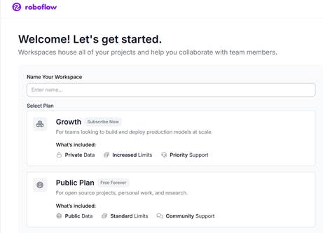
2.1 Prepare your sample for entry into roboflow
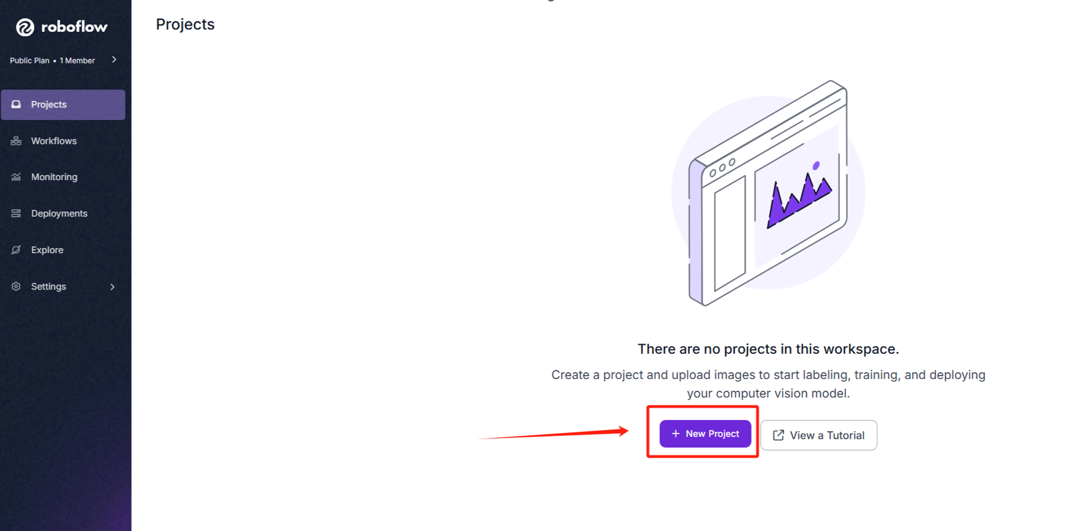
After logging in and registering, create a new workspace.
Create a new project
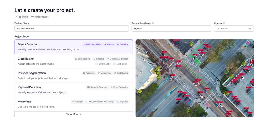
Select the model you want to train and click Create Public Project when you are finished.
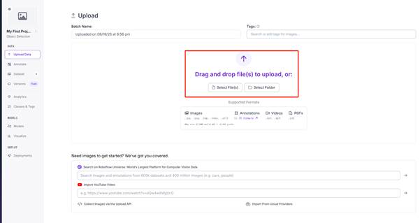
Upload your sample image here.
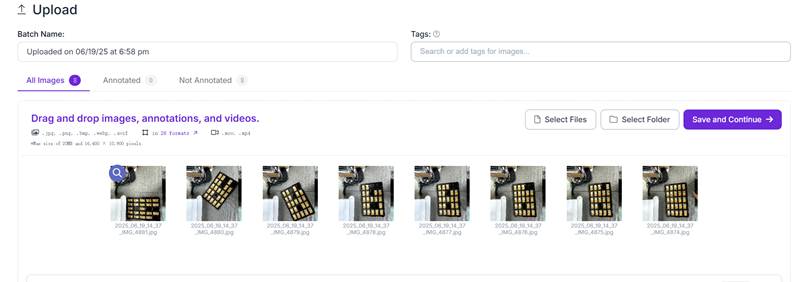
After uploading is complete, click Save and Continue.
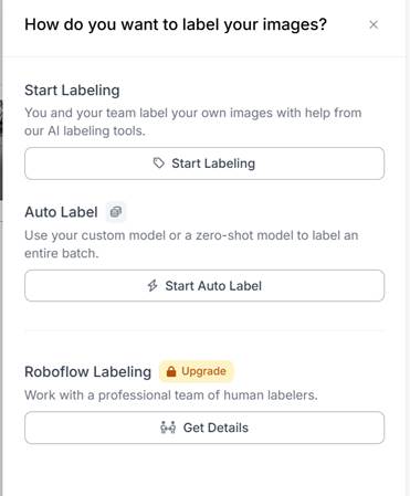
After uploading, mark it and install it according to your needs. Generally, choose the first one
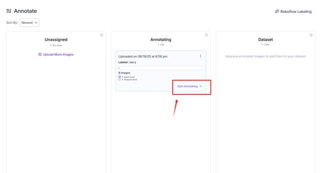
Click Start Annotating to annotate samples.
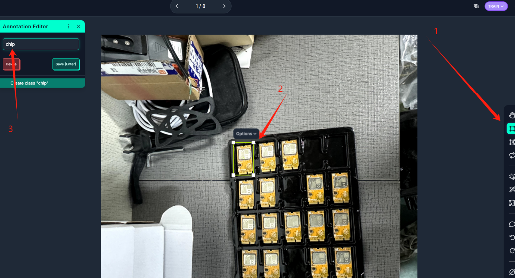
1 Select the tool, 2 Mark, 3 Confirm the mark name
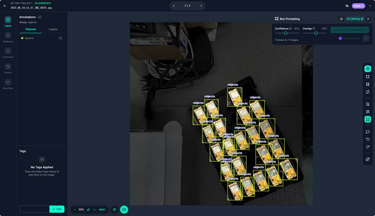
If your annotations are very simple, you can use AI to assist in annotation, which will speed up your efficiency.

It is recommended to distinguish between train valid test.
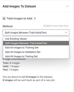
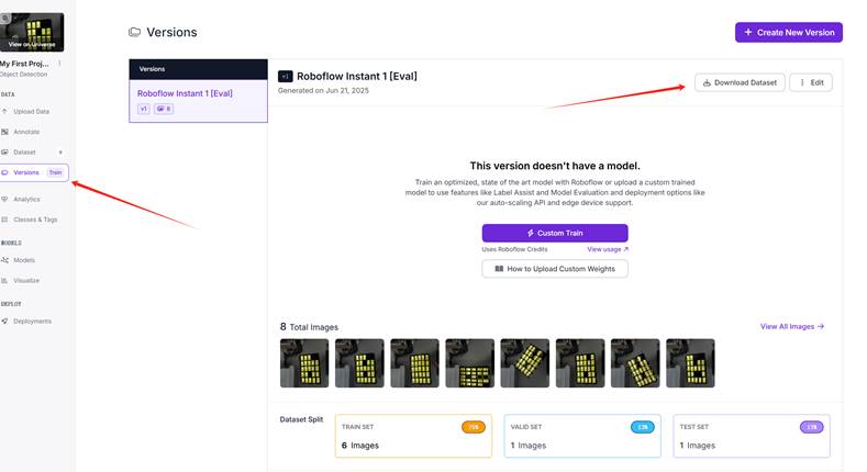
Click Versions and then click Download Dataset.
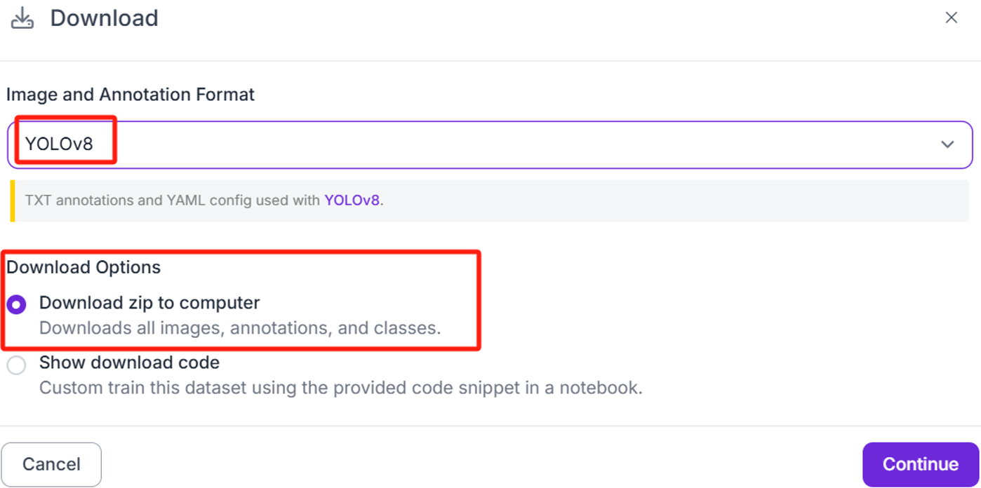
Select YOLO8 and then select Download zip to computer.
2.2 Apply ultralytics to train YOLO8n samples
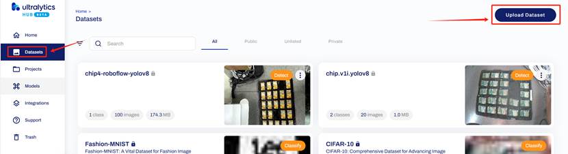
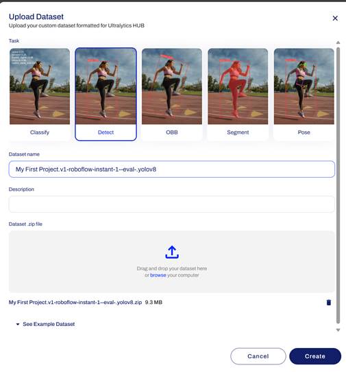
Register and log in https://hub.ultralytics.com/ Select Datasets and click uploadDatasets
Drag the zip archive you just downloaded from roboflow into the box and click create.
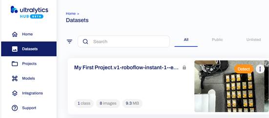
After waiting for the data to be uploaded successfully, click the project to enter the configuration.
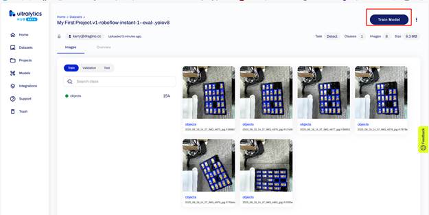
Check whether the box selection mark is correct. If there is no problem, click train model.
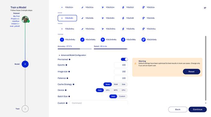
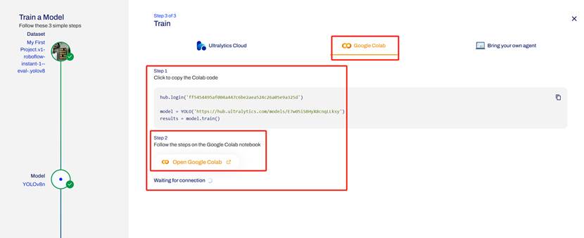
Click to select the YOLO8n model, select 192 for the image size, and then click Continue.
Select Google Colab, copy the relevant code and click open Google Colab to enter.
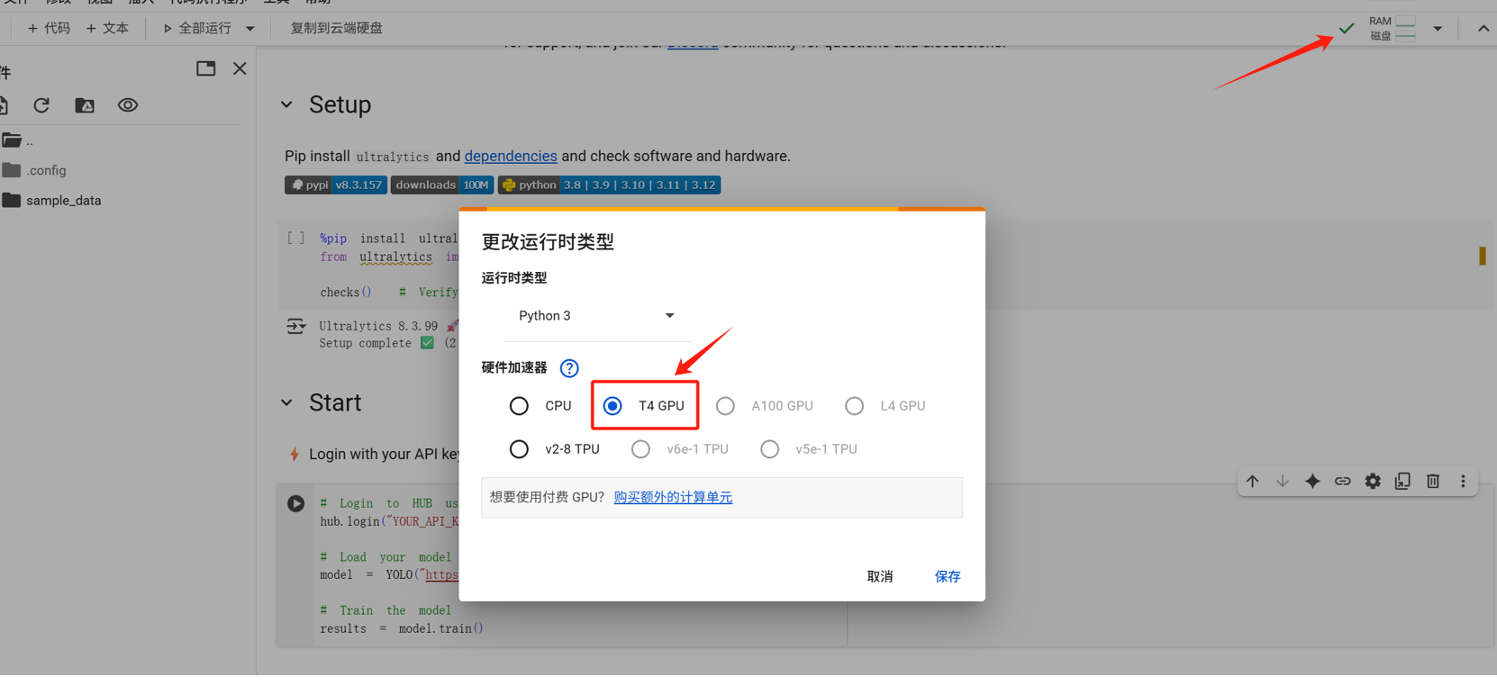
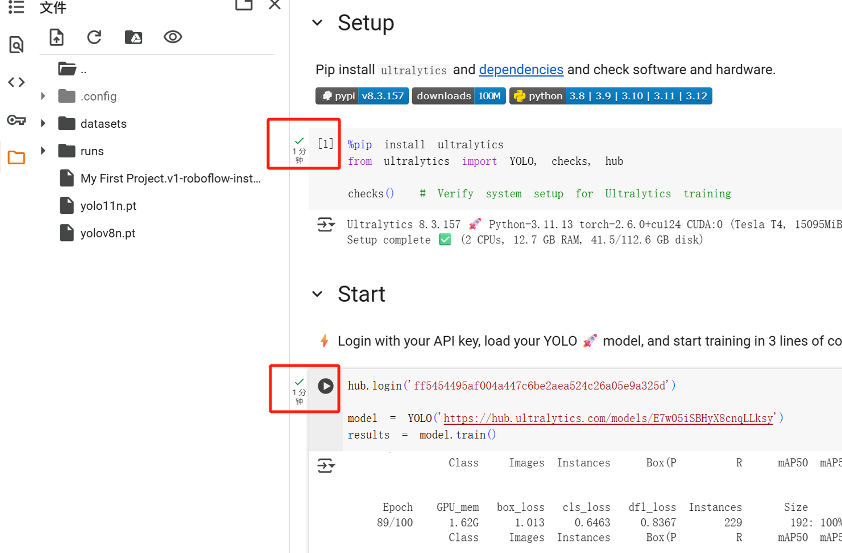
2.3 Apply Google Colab to train samples
After entering Google Colab, select T4 GPU.
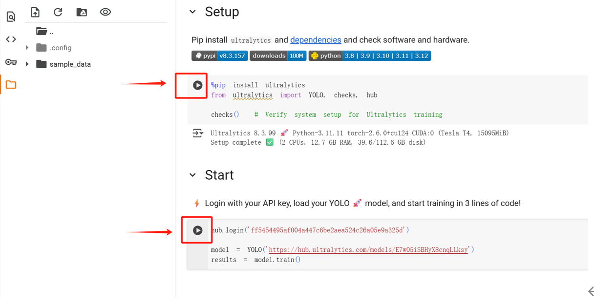
Replace the code copied from ultralytics.
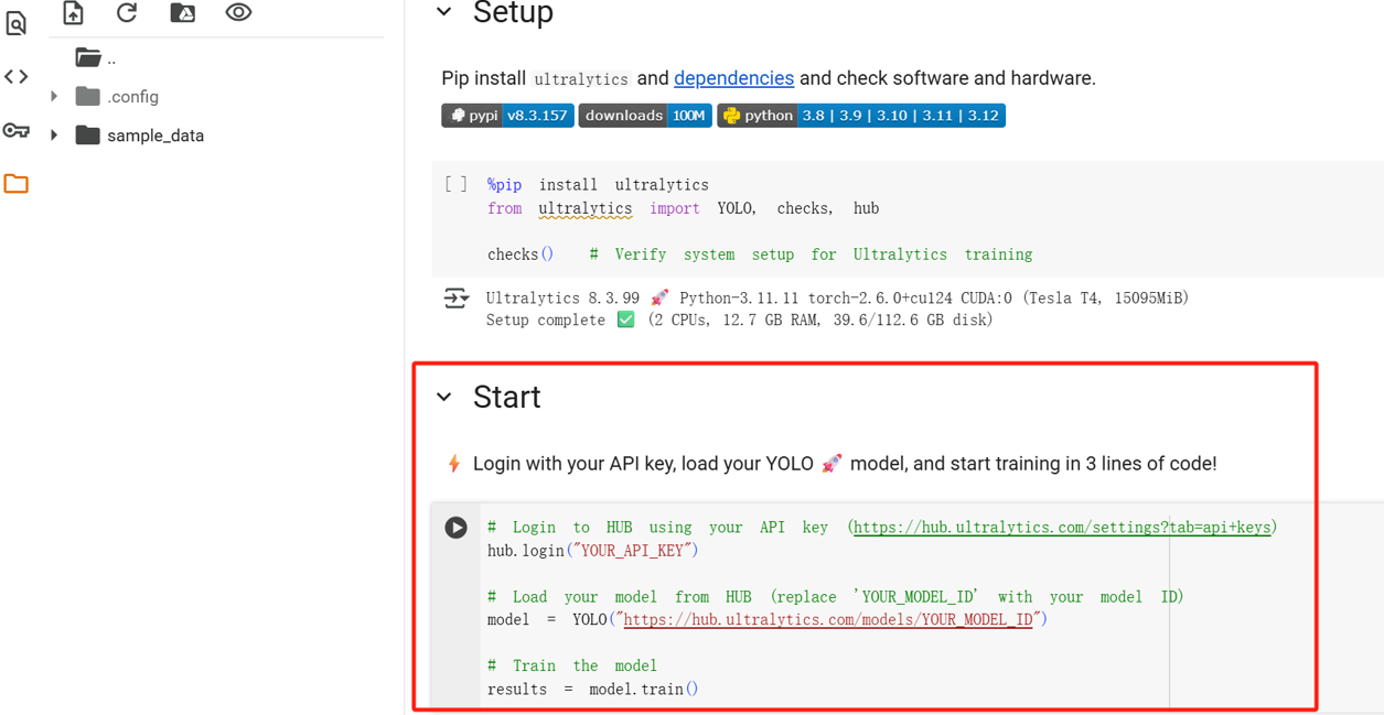
Click the buttons one by one to configure the environment and run the training model.
The time consumed is displayed as the training is completed.
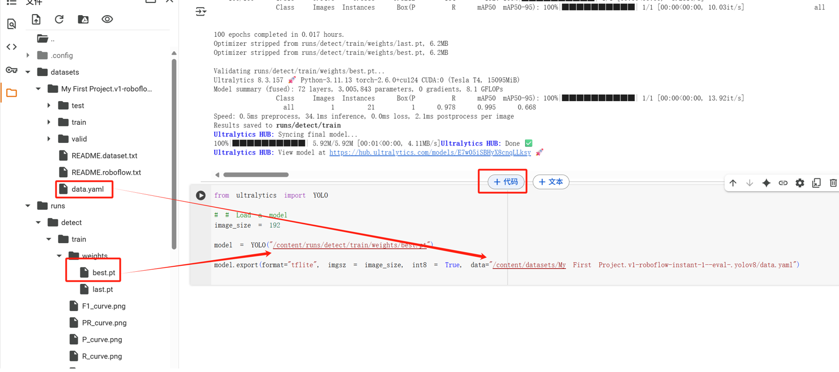
Put the mouse at the end, and the add code will be displayed. Copy and paste the code into it.
from ultralytics import YOLO
# # Load a model
image_size = 192
model = YOLO("/content/runs/detect/train/weights/best.pt")
model.export(format="tflite", imgsz = image_size, int8 = True, data="/content/datasets/My First Project.v1-roboflow-instant-1--eval-.yolov8/data.yaml")
Then fill in the correct best.pt path and data.yaml path
Next, click the button to continue training.
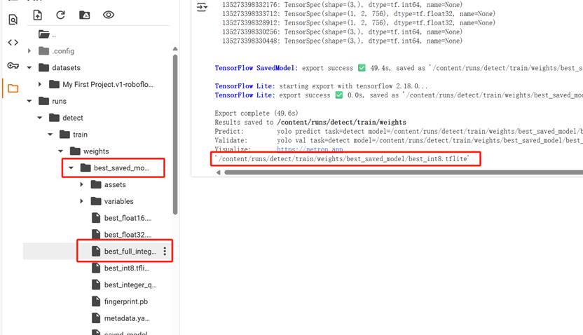
After the training is completed, follow the path to find best_full_integer_quant.tflite, then right-click to download.
2.4 Quantize TFlite files using python
Install Python 3.10 or above Install VC++ 14 or above (such as Visual Studio 2022. Otherwise, an error will be reported when installing Vela Compiler later) Install Vela Compiler Run cmd.exe in the "C:\Program Files\Python\Scripts" directory Execute the command pip3 install ethos-u-vela
https://www.mirrorservice.org/pub/vim/pc/Download and install vim90w32.zip
Put the downloaded TFlite file in the Scripts directory Then run the following command
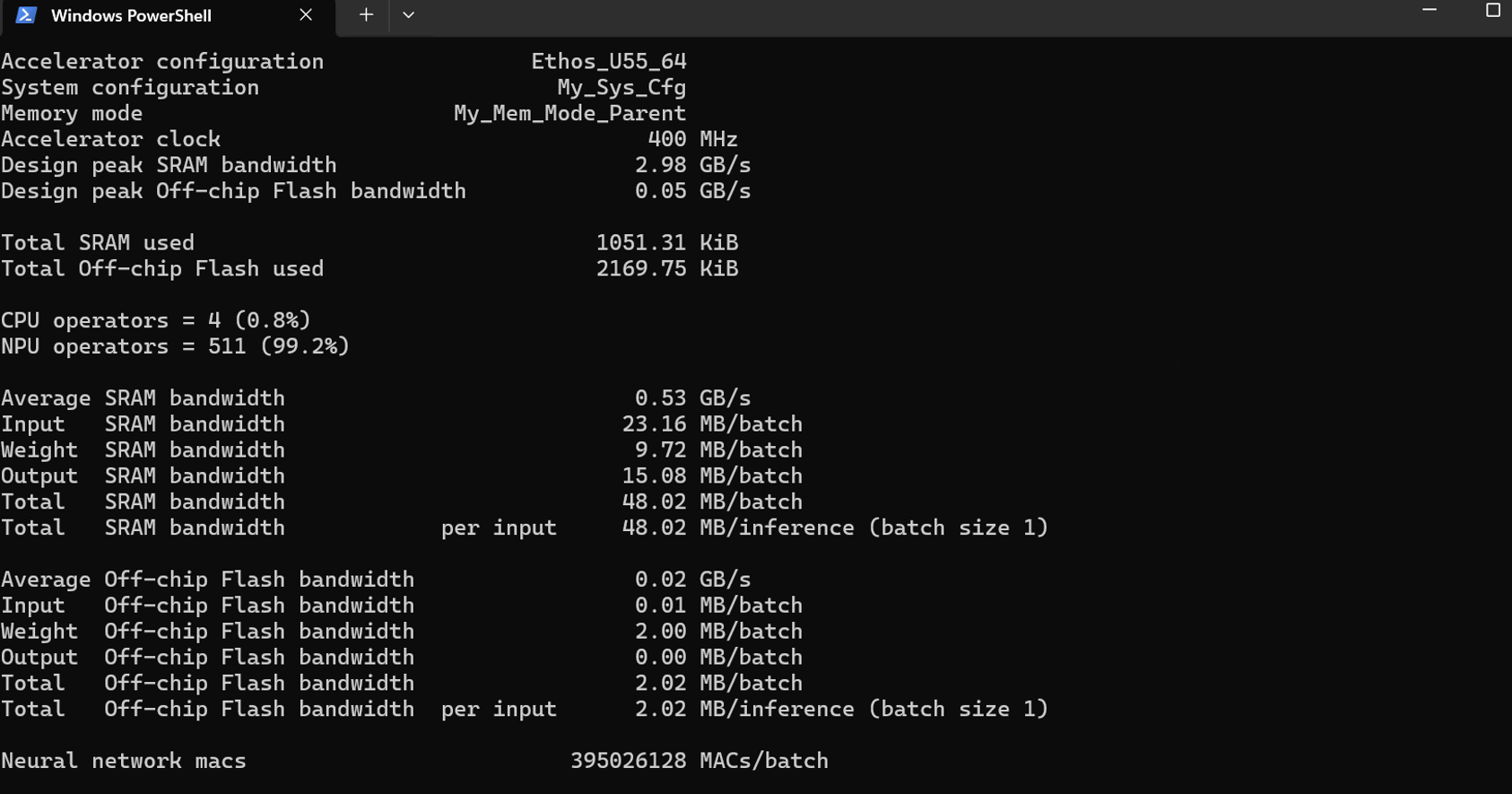
vela --accelerator-config ethos-u55-64 --config himax_vela.ini --system-config My_Sys_Cfg --memory-mode My_Mem_Mode_Parent .\best_full_integer_quant.tflite
If the following content is displayed, the quantization is successful
2.5 Burn quantized TFLITE file
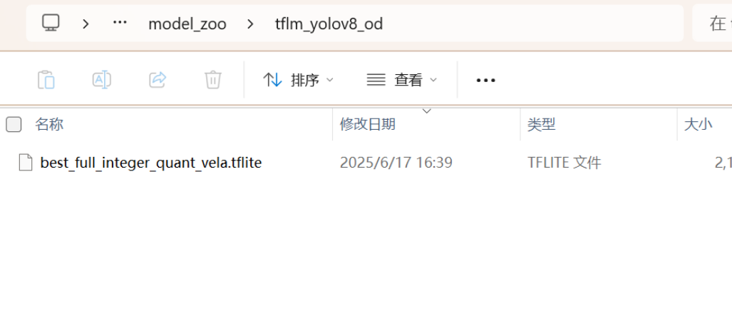
After downloading the relevant environment configuration, enter model_zoo and put the quantized TFlite into \Seeed_Grove_Vision_AI_Module_V2-main\model_zoo\tflm_yolov8_od
Open a command prompt, go to the corresponding folder, and enter:
Open the serial port command:
python xmodem\xmodem_send.py --port=COM45 --baudrate=921600 --protocol=xmodem
Burn the image command:
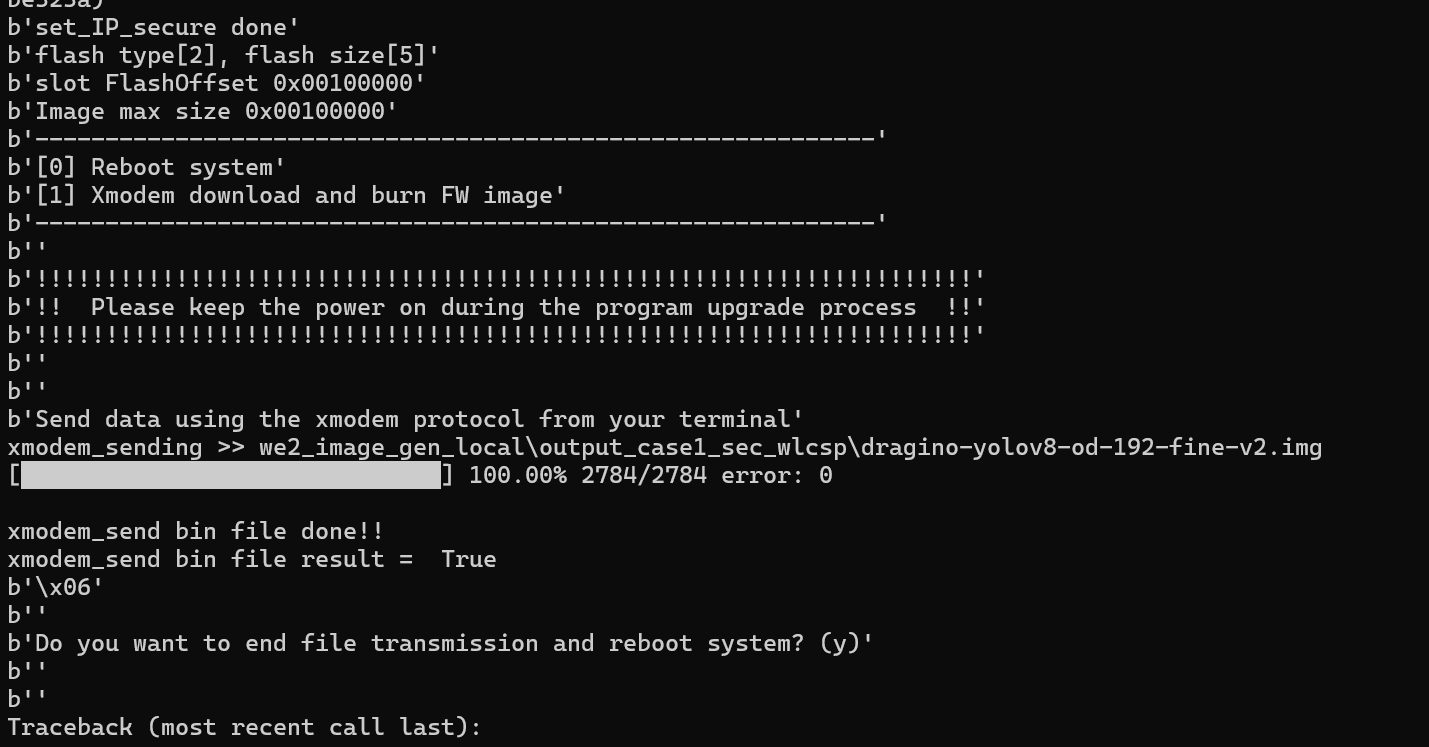
python xmodem\xmodem_send.py --port=COM45 --baudrate=921600 --protocol=xmodem --file=we2_image_gen_local\output_case1_sec_wlcsp\dragino-yolov8-od-192-fine-v2.img
Burn tflite command:
python xmodem\xmodem_send.py --port=COM45 --baudrate=921600 --protocol=xmodem --model="model_zoo\tflm_yolov8_od\best_full_integer_quant_vela.tflite 0xB7B000 0x00000
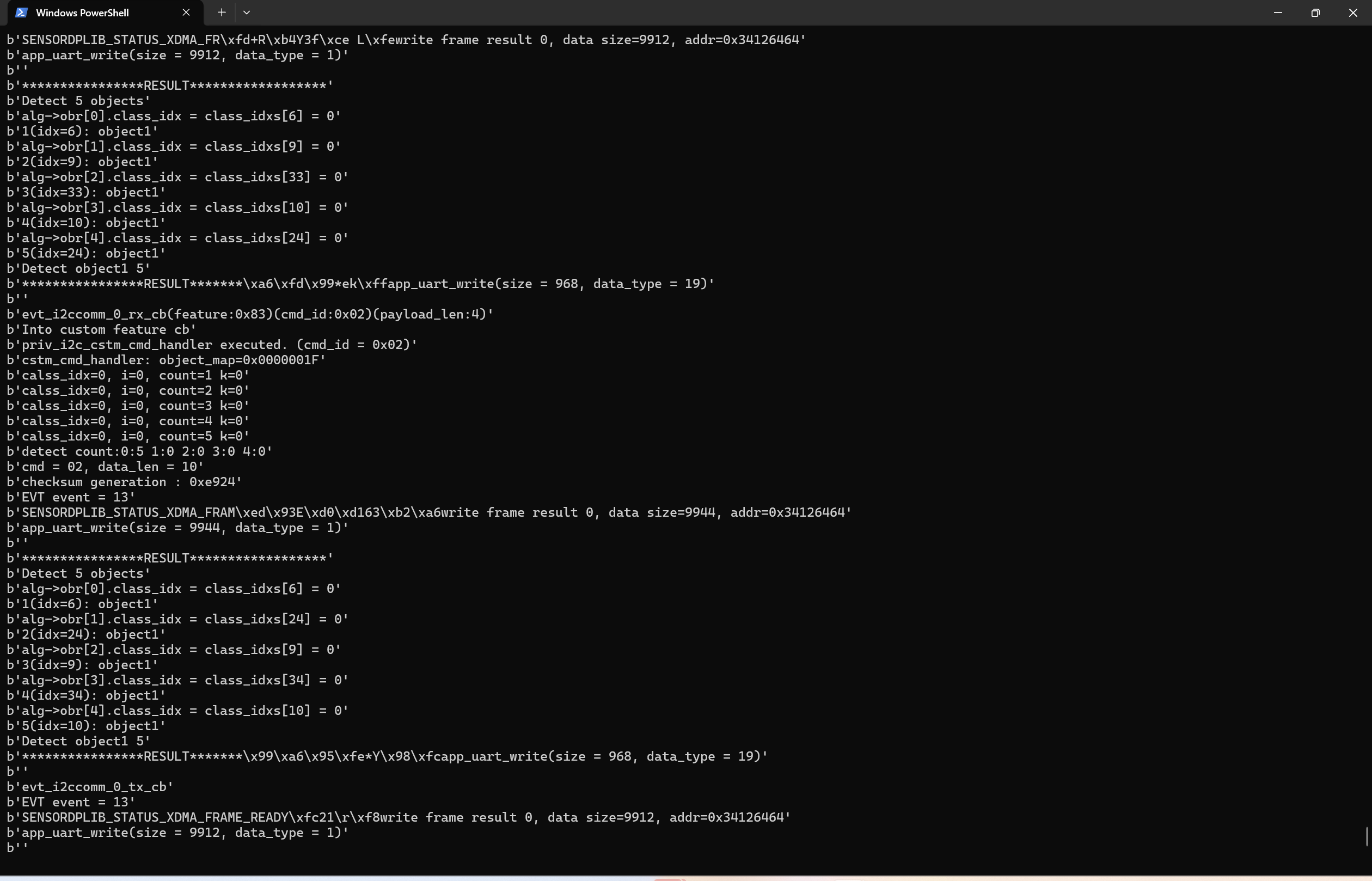
When this page appears, reconnect the USB and then open the serial port to check if everything is working properly. In this example, 5 trained objects were recognized.
5. Order Info
5.1 Main Device
Part Number: AI52-XX
XX : The default frequency band
- AS923: LoRaWAN AS923 band
- AU915: LoRaWAN AU915 band
- EU433: LoRaWAN EU433 band
- EU868: LoRaWAN EU868 band
- KR920: LoRaWAN KR920 band
- US915: LoRaWAN US915 band
- IN865: LoRaWAN IN865 band
- CN470: LoRaWAN CN470 band
6. Packing Info
Package Includes:
- PF52 x 1
7. Support
- Support is provided Monday to Friday, from 09:00 to 18:00 GMT+8. Due to different timezones we cannot offer live support. However, your questions will be answered as soon as possible in the before-mentioned schedule.
- Provide as much information as possible regarding your enquiry (product models, accurately describe your problem and steps to replicate it etc) and send a mail to support@dragino.com.
8. FCC Warning
This device complies with part 15 of the FCC Rules.Operation is subject to the following two conditions:
(1) This device may not cause harmful interference;
(2) this device must accept any interference received,including interference that may cause undesired operation.
9. Appendix I:According to the use
0