The Things Network (TTN)
1. The Things Network-V3
1.1 Introduction
1.1.1 What is The Things Network
The Things Network is a global collaborative Internet of Things ecosystem that creates networks, devices and solutions using LoRaWAN.
The Things Network runs The Things Stack Community Edition, which is a crowdsourced, open and decentralized LoRaWAN network. This network is a great way to get started testing devices, applications, and integrations, and get familiar with LoRaWAN.
1.1.2 Login or crate an account
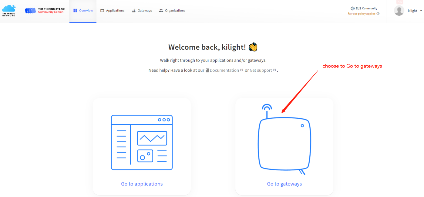
Login or create an account to get started with The Things Network and start using The Things Stack Console.
Once you have an account,get started by following steps for adding Gateway,Device and Intergrations.
1.1.3 List the support products and Requirements
LoRaWAN Gateway model: Existing Gateway
2. Gateway Registration for Semtech UDP
Note: Steps 2 and 3 are different connection methods, the user only needs to choose one of them
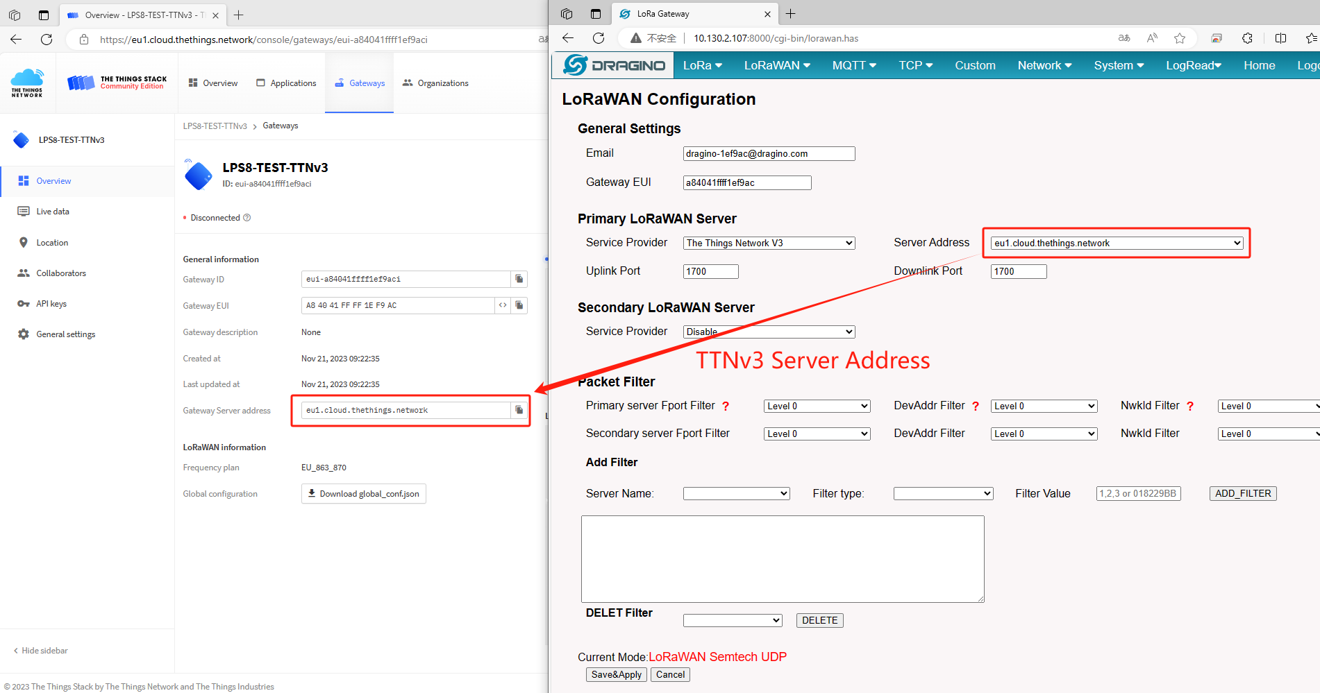
2.1 Primary LoRaWAN Server
Register Gateway
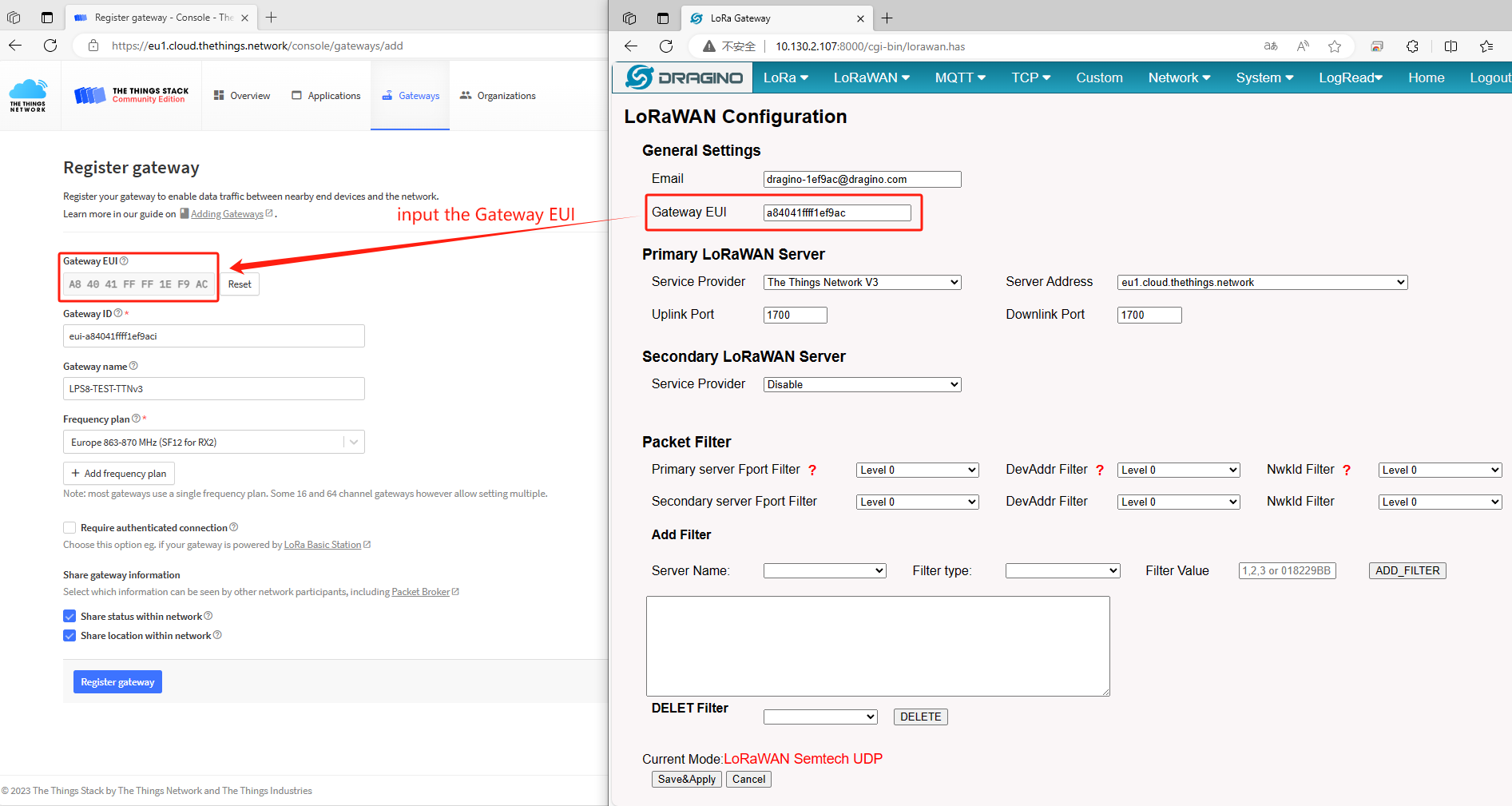
Put Gateway ID
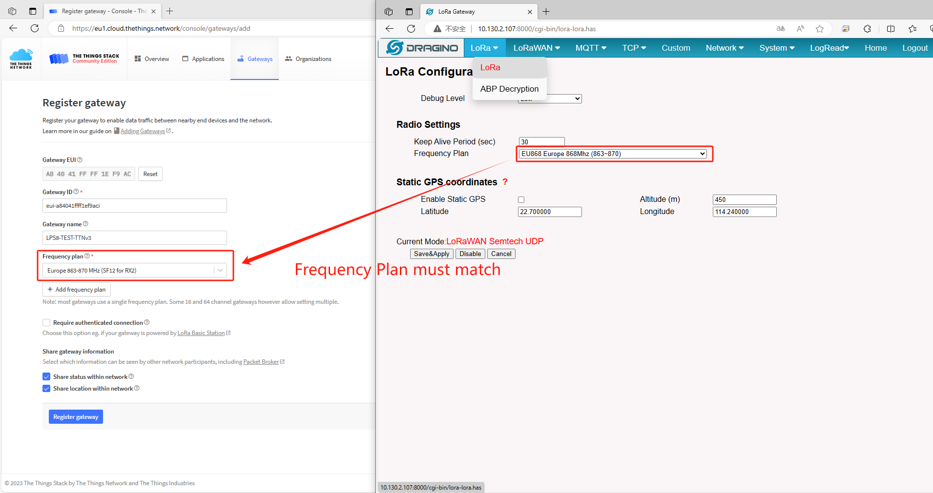
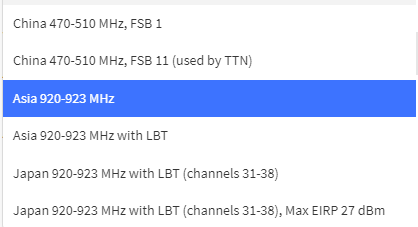
Choose Frequency Band
Note:
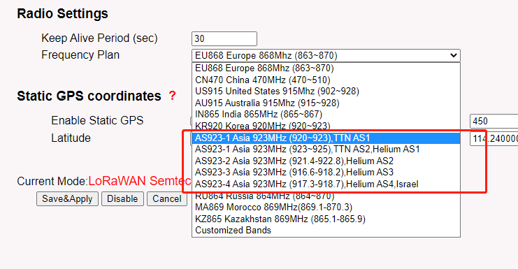
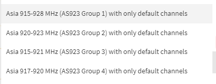
DRAGINO - Frequency Plan list --------------- The Thing Network Frequency Plan List
AS923-1 (920-923) [ ] --------------- Asia 920-923 Mhz
AS923-1 (923-925) --------------- Asia 915-928 Mhz (AS923 Group 1)with only default channels
AS923-2 (921.4-922.8) --------------- Asia 920-923 Mhz (AS923 Group 2)with only default channels
AS923-3 (916.6-918.2) --------------- Asia 915-921 Mhz (AS923 Group 3)with only default channels
AS923-4 (917.3-918.7) --------------- Asia 917-920 Mhz (AS923 Group 4)with only default channels
 {#Iimage-20220526134919-5.png .wikigeneratedid xwiki-translated-attribute-_mstalt="433602"}
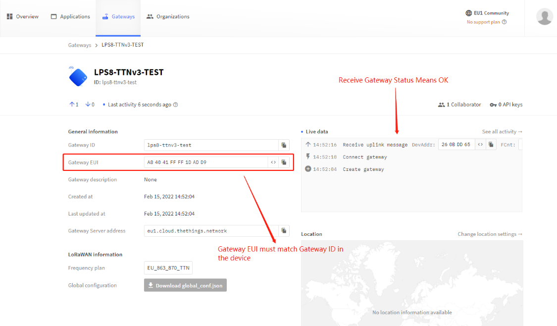
Show Status
2.2 Secondary LoRaWAN Server
2.2.1 Introduction
The Dragino gateway has supports the Secondary server settings.
2.2.2 Below list the support products and Requirements:
1. LoRaWAN Gateway model: LIG16,LG308N, DLOS8N,LPS8N
2. Firmware version since : lgw--build-v5.4.1644658774
2.2.3 Example
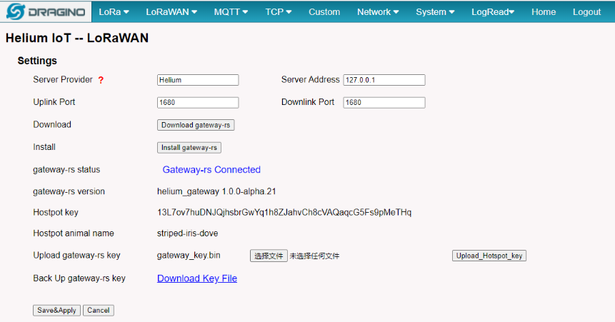
The following takes Helium as a Secondary LoRaWAN server as an example
2.2.4 Step 1: Download and Install the helium gateway-rs
The users is needing to download and install the helium gateway-rs then click the button of Save&Apply.
 {#Iimage-20220526135049-6.png .wikigeneratedid xwiki-translated-attribute-_mstalt="432432"}
Download and Install gateway-rs
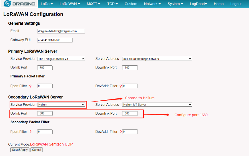
2.2.5 Step 2: Back to Semtech UDP page
Back to the page of Semtech UDP check the secondary server settings and click the button of Save&Apply.
 {#Iimage-20220526135125-7.png .wikigeneratedid xwiki-translated-attribute-_mstalt="431106"}
Configuration of helium
3. Gateway Registration for Basics Station
3.1 Introduction
The LoRa Basics™ Station protocol simplifies the management of large-scale LoRaWAN networks. LoRa Basics™ Station is the preferred way of connecting Gateways to The Things Stack. The LoRa Basics Station doc
Note: Steps 2 and 3 are different connection methods, the user only needs to choose one of them Below list the support products and Requirements:
2. Firmware version since : lgw--build-v5.4.1640315898
What do you need to prepare?
A gateway that can access the internet normally
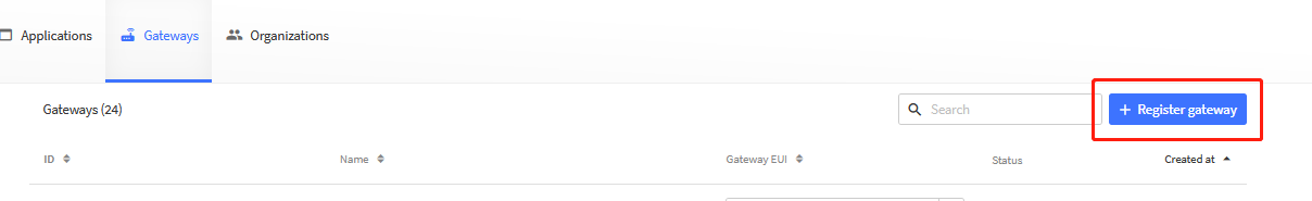
3.2 Step 1: Register Gateway
[The example for] the [EU:]
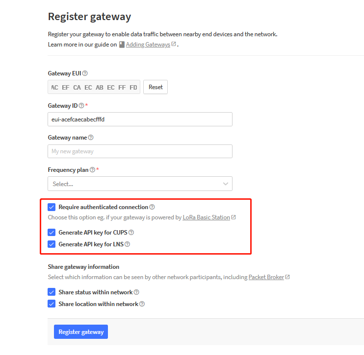
Click the 'Register Gateway' button will get this page to register the gateway from The Thing Network Console gateway page.
 {#Iimage-20230728143449-2.png .wikigeneratedid xwiki-translated-attribute-_mstalt="433108"}
Register Gateway
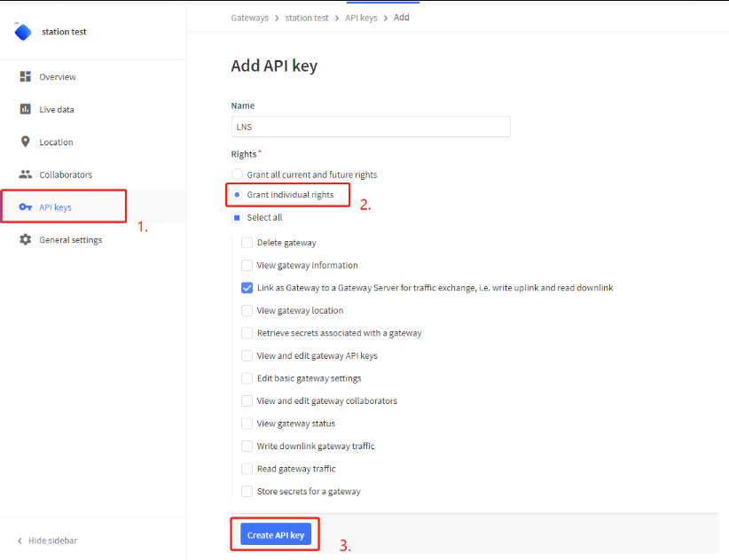
3.3 Step 2: Create the API key
API Key can be created manually ---> if users forgot to check the check box or switch to basic station mode from the Semtech UDP mode
or generate by TTN by checking the check box when registering the gateway --->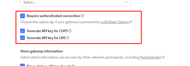 {#Iimage-20230728143505-3.png .wikigeneratedid xwiki-translated-attribute-_mstalt="431132"}
1.) Generated by TTH
Users need to download these two key files and fill them into the gateway's TTN Basics Station configuration,
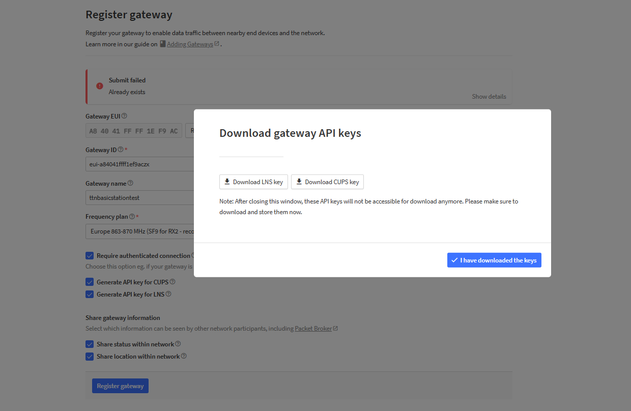
Note: The "Authorization: Bearer " field should not be entered in the TTN Basics Station configuration of the gateway
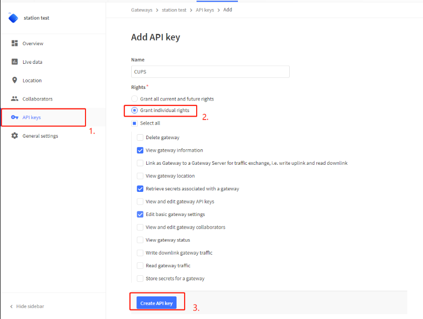
**2.) Manually create API KEY: **
CUPS API KEY
 {#Iimage-20220526135349-9.png .wikigeneratedid xwiki-translated-attribute-_mstalt="434460"}
LNS API KEY
 {#Iimage-20220526135428-10.png .wikigeneratedid xwiki-translated-attribute-_mstalt="453791"}
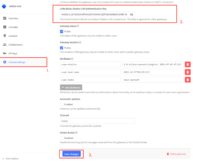
Note: If your API is generated by yourself you have to update the key to the gateway setting.
Update the gateway setting
In the LoRa Basics Station LNS Authentication Key field, paste the API key you generated in the previous step.
 {#Iimage-20220526135528-11.png .wikigeneratedid xwiki-translated-attribute-_mstalt="454480"}
paste the API key
3.5 Step 4: Access the gateway GUI
User need to update the API key and install the Certificatec
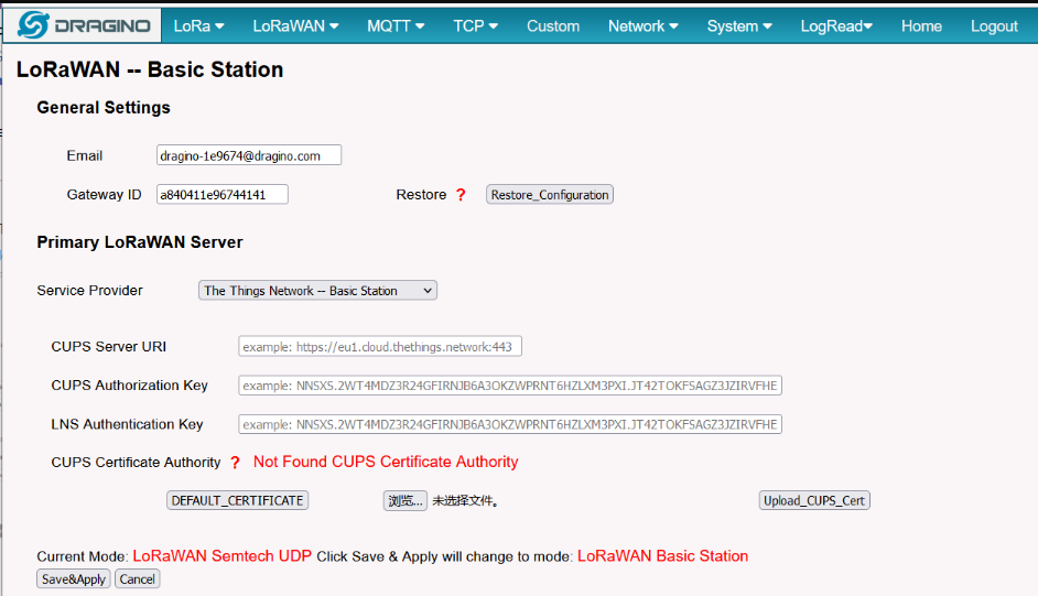 {#Iimage-20220526135601-12.png .wikigeneratedid xwiki-translated-attribute-_mstalt="452153"}
Access the gateway GUI
3.6 Step 5: Configure Station
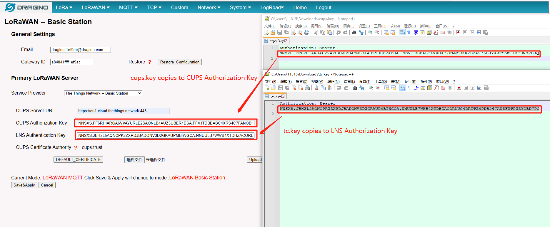
User need to input Server URI, Server CUPS Key and LNS Key, as well as install CUPS certificate.
just to clarify:
::: box
CUPS Server URI --> Server Address, Example: https://eu1.cloud.thethings.network:443\
CUPS Authorization Key --> Server CUPS API Key
LNS Authorization Key --> Server LNS API Key
CUPS certificate --> Server CA(user can use the button to install the certificate by default)
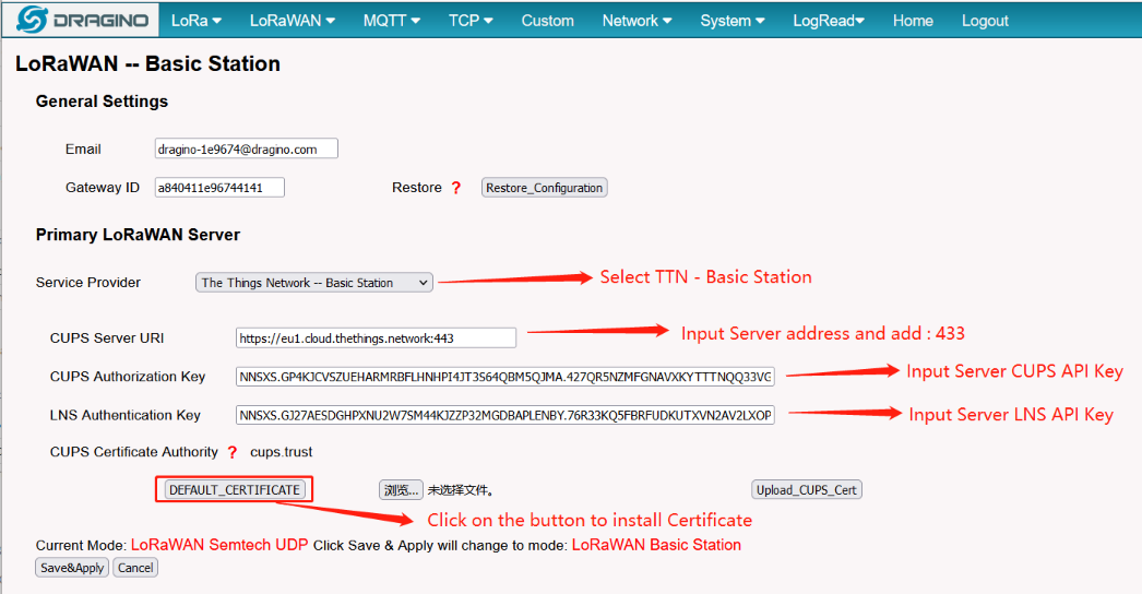 {#Iimage-20220526135654-13.png .wikigeneratedid xwiki-translated-attribute-_mstalt="455169"}
Congfigure Station
3.7 Start Station
When the user has finished the configuration,Please click Sace&Apply to start station to connect The Things Network.
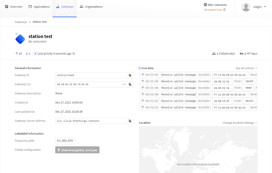
3.8 Successful Connection
If user completes the above steps,which will see live date in the TTN.
 {#Iimage-20220526135734-14.png .wikigeneratedid xwiki-translated-attribute-_mstalt="455208"}
Station live date
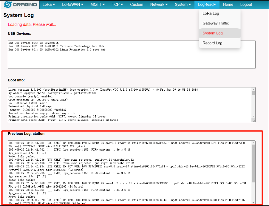
3.9 Trouble Shooting
User can check the station log in the** [LogRead --> System Log ]**page.
 {#Iimage-20220526135845-15.png .wikigeneratedid xwiki-translated-attribute-_mstalt="456560"}
Station Log
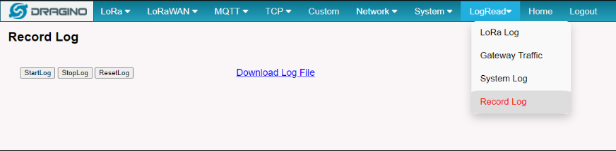
and recode the station log in the LogRead --> Recode Log page.
 {#Iimage-20220526135940-16.png .wikigeneratedid xwiki-translated-attribute-_mstalt="455559"}
Recore Log
4. Configure node connection to TTNv3
Following is an example for how to join the TTN v3 LoRaWAN Network.
The gateway is already set up to connect to the TTN network, so we now need to configure the TTNv3 server.
We take LES01 as an example.
4.1 Step 1
Create a device in TTN with the OTAA keys from LSE01.
Each LSE01 is shipped with a sticker with the default device EUI as below:
You can enter this key in the LoRaWAN Server portal. Below is TTN screen shot:
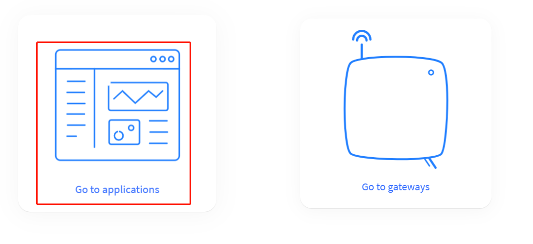
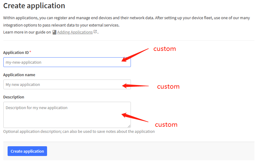
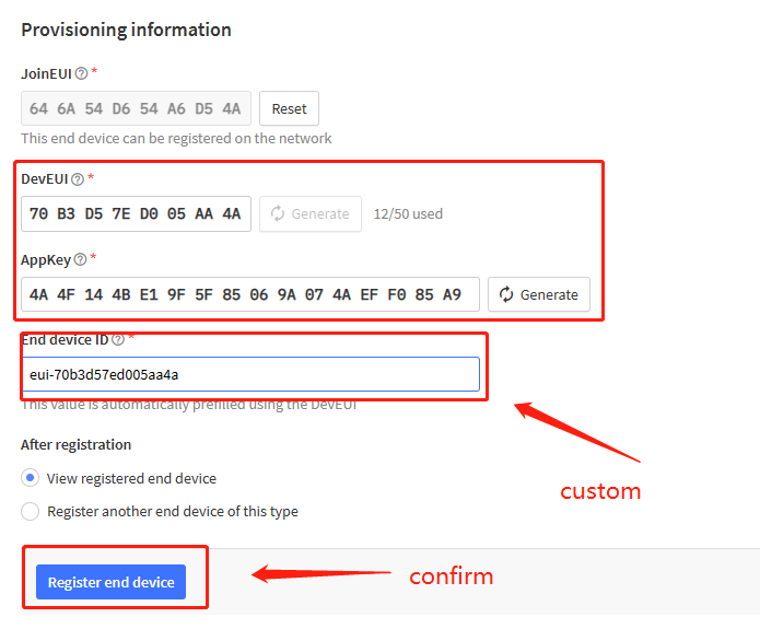
First create an application and fill in the custom information in it

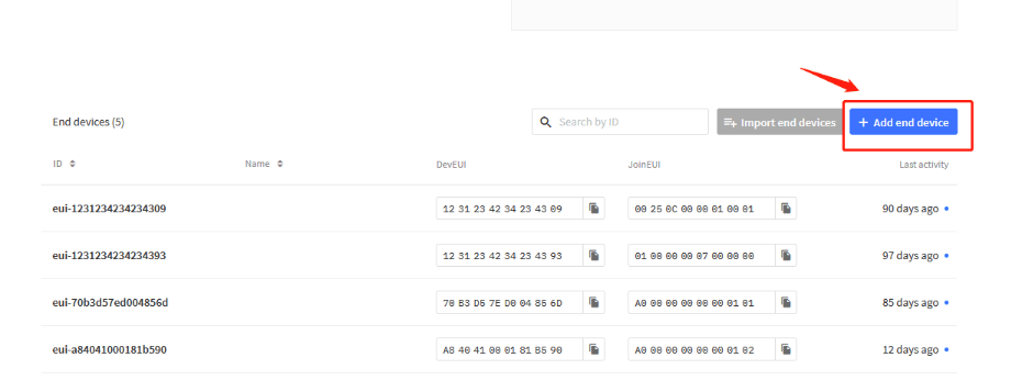
Add a node device to the application
 {#Iimage-20220526140044-18.png .wikigeneratedid xwiki-translated-attribute-_mstalt="453648"}
4.2 Step 2
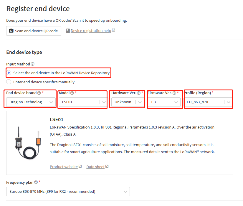
There are all our nodes in the repository. Users can choose the corresponding brand, model, firmware version and frequency.The decoder and configuration information of the node are pre-configured.Users do not need to configure them.
4.3 Step 3
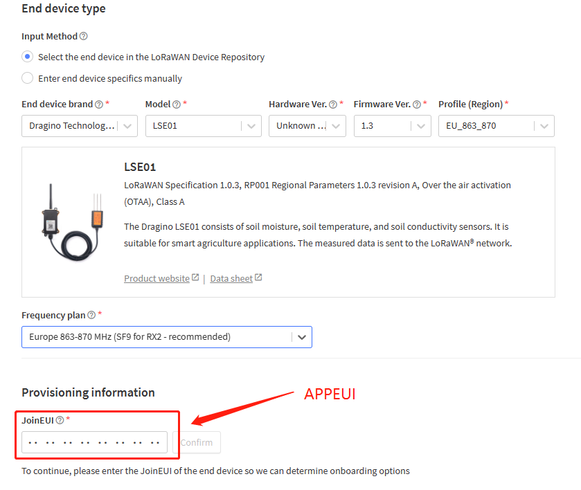
Add APP EUI in the application:
4.4 Step 4
Add APP KEY and DEV EUI:
5. TTN V3 integrated into MQTT server
5.1 Introduction
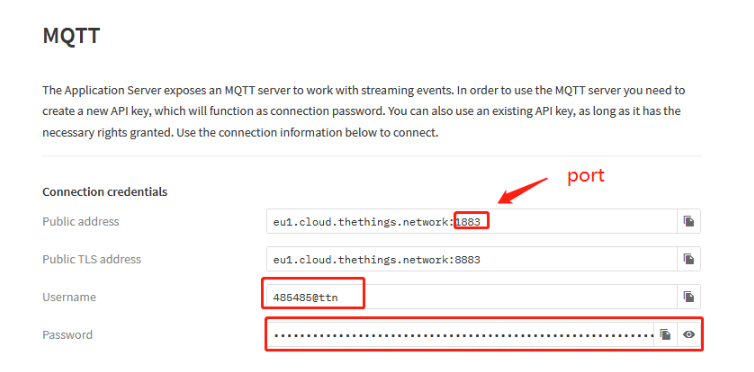
The Application Server exposes an MQTT server to work with streaming events. In order to use the MQTT server you need to create a new API key, which will function as connection password. You can also use an existing API key, as long as it has the necessary rights granted.
5.2 Create device steps at MQTT
The user creates a new API KEY after creating a device on TTN V3.
Then copy the password and open MQTT.fx.
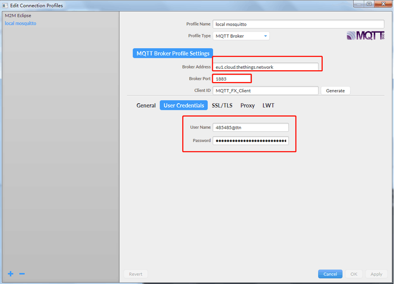
Fill in Broker Address and Broker port.
 {#Iimage-20220526140347-22.png .wikigeneratedid xwiki-translated-attribute-_mstalt="453700"}
Fill in the username and password into MQTT.
 {#Iimage-20220526140420-23.png .wikigeneratedid xwiki-translated-attribute-_mstalt="451373"}
The Application Server publishes uplink traffic on the following topics:
::: box
v3/{application id}@{tenant id}/devices/{device id}/join
v3/{application id}@{tenant id}/devices/{device id}/up
v3/{application id}@{tenant id}/devices/{device id}/down/queued
v3/{application id}@{tenant id}/devices/{device id}/down/sent
v3/{application id}@{tenant id}/devices/{device id}/down/ack
v3/{application id}@{tenant id}/devices/{device id}/down/nack
v3/{application id}@{tenant id}/devices/{device id}/down/failed
v3/{application id}@{tenant id}/devices/{device id}/service/data
v3/{application id}@{tenant id}/devices/{device id}/location/solved
Note[: Remember that the format of these topics for The Things Stack Open Source would contain {application id} instead of {application id}@{tenant id}.]
 {#Iimage-20220526140452-24.png .wikigeneratedid xwiki-translated-attribute-_mstalt="453401"}
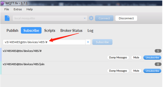
While you could subscribe to all of these topics separately, for the simplicity of this tutorial we use # to subscribe to all topics, i.e. to receive all uplink traffic.
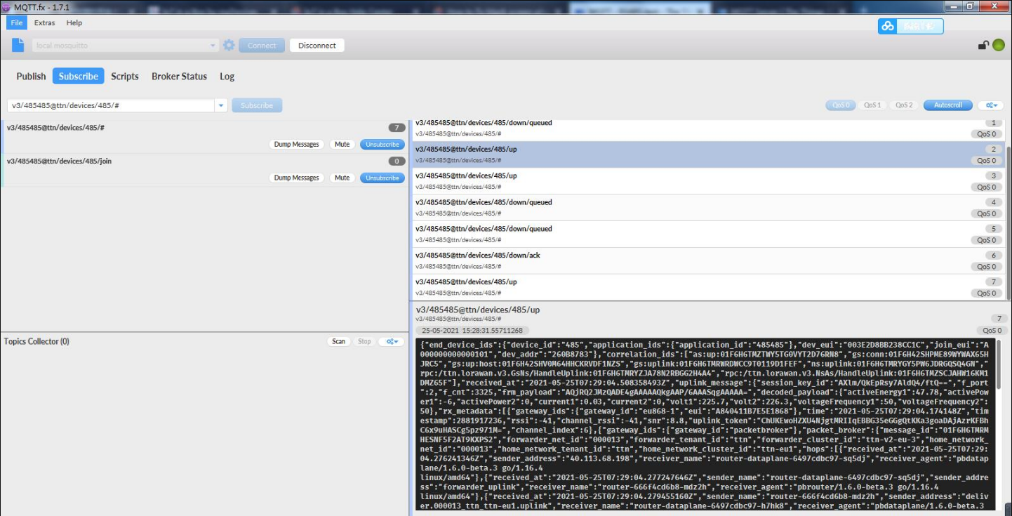 {#Iimage-20220526140708-25.png .wikigeneratedid xwiki-translated-attribute-_mstalt="455117"}
Downlinks can be scheduled by publishing the message to the topic v3/{application id}@{tenant id}/devices/{device id}/down/push.
Note[: Remember that the format of this topic for The Things Stack Open Source deployment would be v3/{application id}/devices/{device id}/down/push.]
Instead of /push, you can also use /replace to replace the downlink queue. Replacing with an empty array clears the downlink queue. Example:
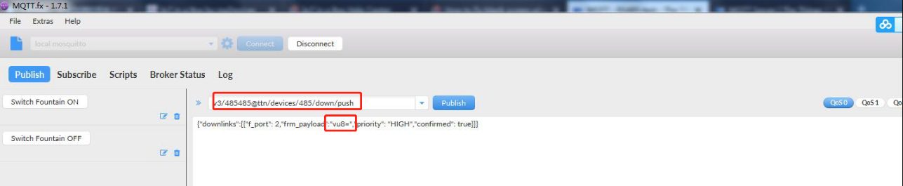 {#Iimage-20220526140856-26.png .wikigeneratedid xwiki-translated-attribute-_mstalt="456755"}
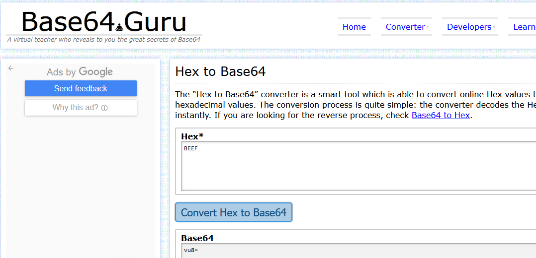
To send an unconfirmed downlink message to the device dev1 in application app1 in tenant tenant1 with the hexadecimal payload BE EF on FPort 15 with normal priority, use the topic v3/app1@tenant1/devices/dev1/down/push with the following contents: vu8=, which is the Base64 format for Hex BE EF . HEX to Base64 online converter tool.
Below is the TTN output for this downlink command.
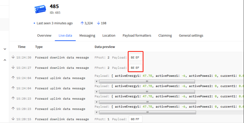 {#Iimage-20220526140936-27.png .wikigeneratedid xwiki-translated-attribute-_mstalt="456794"}
5.3 Send Downlink message
How to configure downlink in TTN V3?
A few examples: set the transmission interval to 90 seconds.
Downlink command: 01 00 00 5A
 {#Iimage-20220526141021-28.png .wikigeneratedid xwiki-translated-attribute-_mstalt="452647"}
downlink
After sending, you can view it in live data.
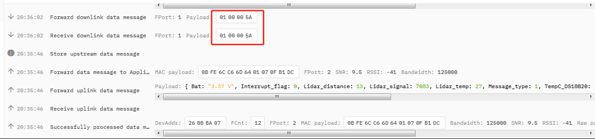 {#Iimage-20220526141052-29.png .wikigeneratedid xwiki-translated-attribute-_mstalt="454337"}
downlink
When downlink is successfully sent, the downlink information can be received on the serial port.
Note[:** If the downlink byte sent is longer, the number of bytes will be displayed.**]
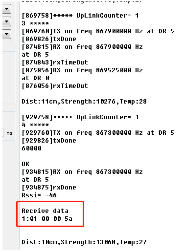 {#Iimage-20220526141116-30.png .wikigeneratedid xwiki-translated-attribute-_mstalt="451672"}
downlink
If you want to get a successful reply to send downlink in TTN v3. You need to set the response level.
If the equipment uses CLASS A. You can set AT+RPL=2[ ]or send the downlink command: 2102
If the equipment uses CLASS C. You can set** [AT+RPL=4** or send the downlink command: 2104
When the device successfully receives the downlink, the server will receive a confirmation packet of 00.
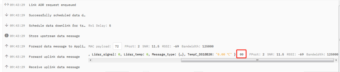 {#Iimage-20220526141149-31.png .wikigeneratedid xwiki-translated-attribute-_mstalt="454038"}
downlink
6. Route TTN data to Node-Red
Users can create an MQTT integration by following the steps described in "5.TTN V3 Integrated into MQTT Server{xwiki-translated-attribute-_mstmutation="1"}"
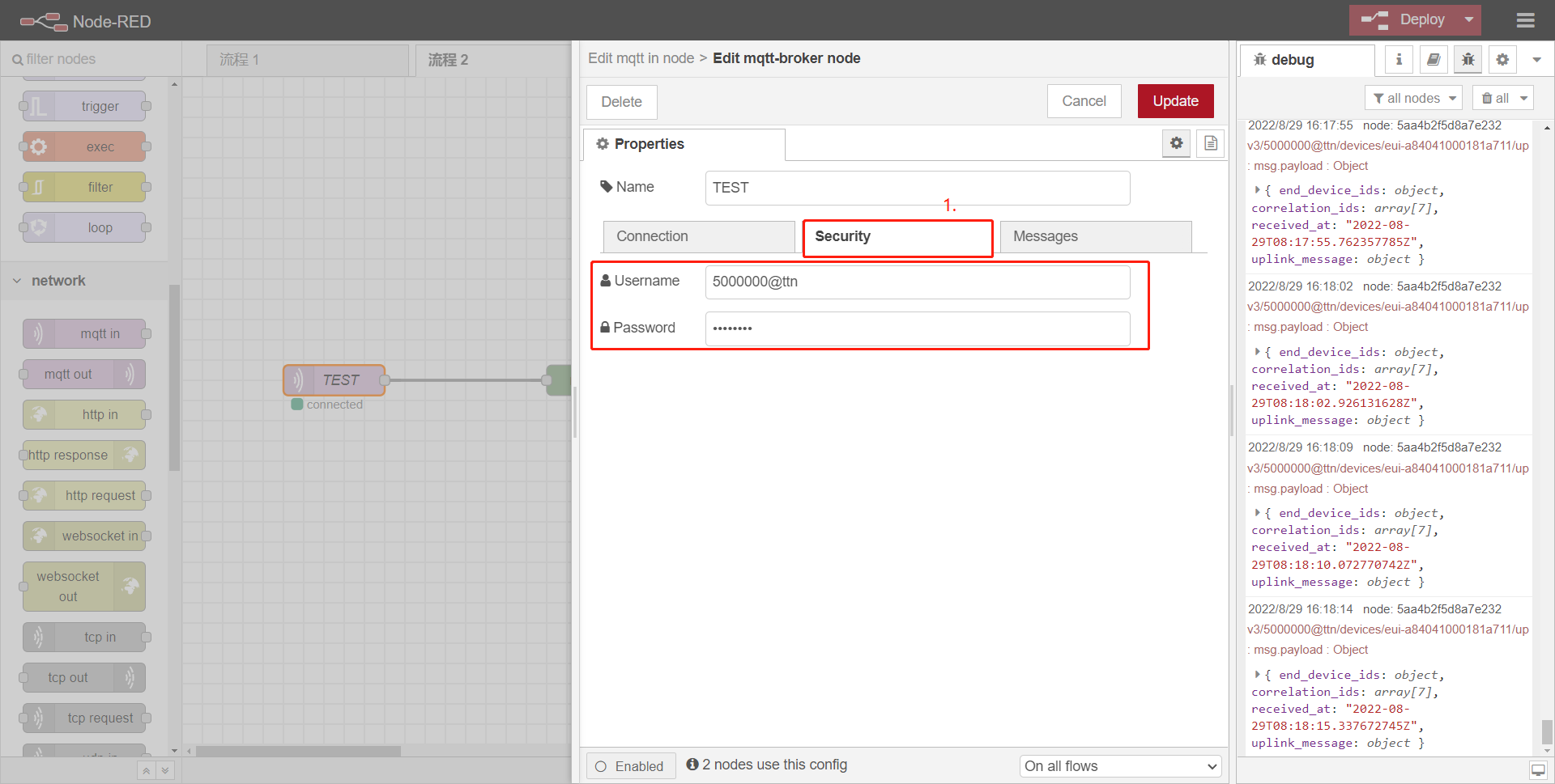
6.1 Edit mqtt-broker node
Users need to configure the TTN MQTT server address and port, Such as:
Server : eu1.cloud.thethings.network
Port : 1883
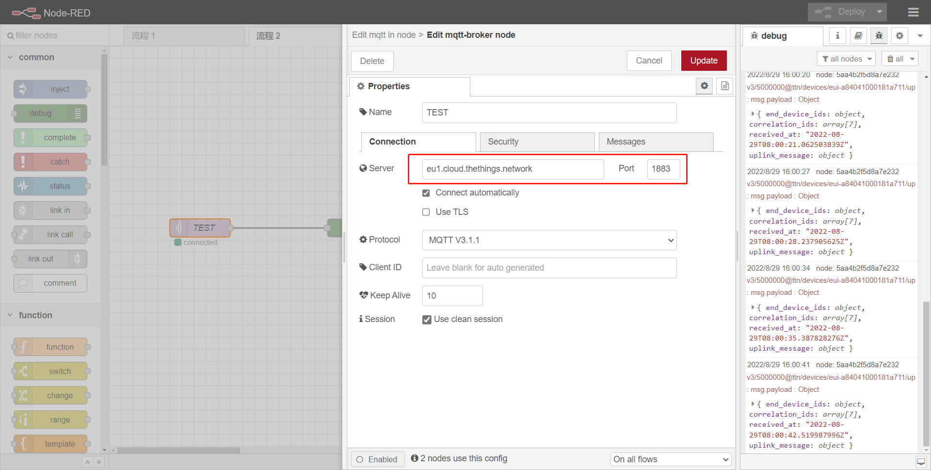
Enter Username and Password
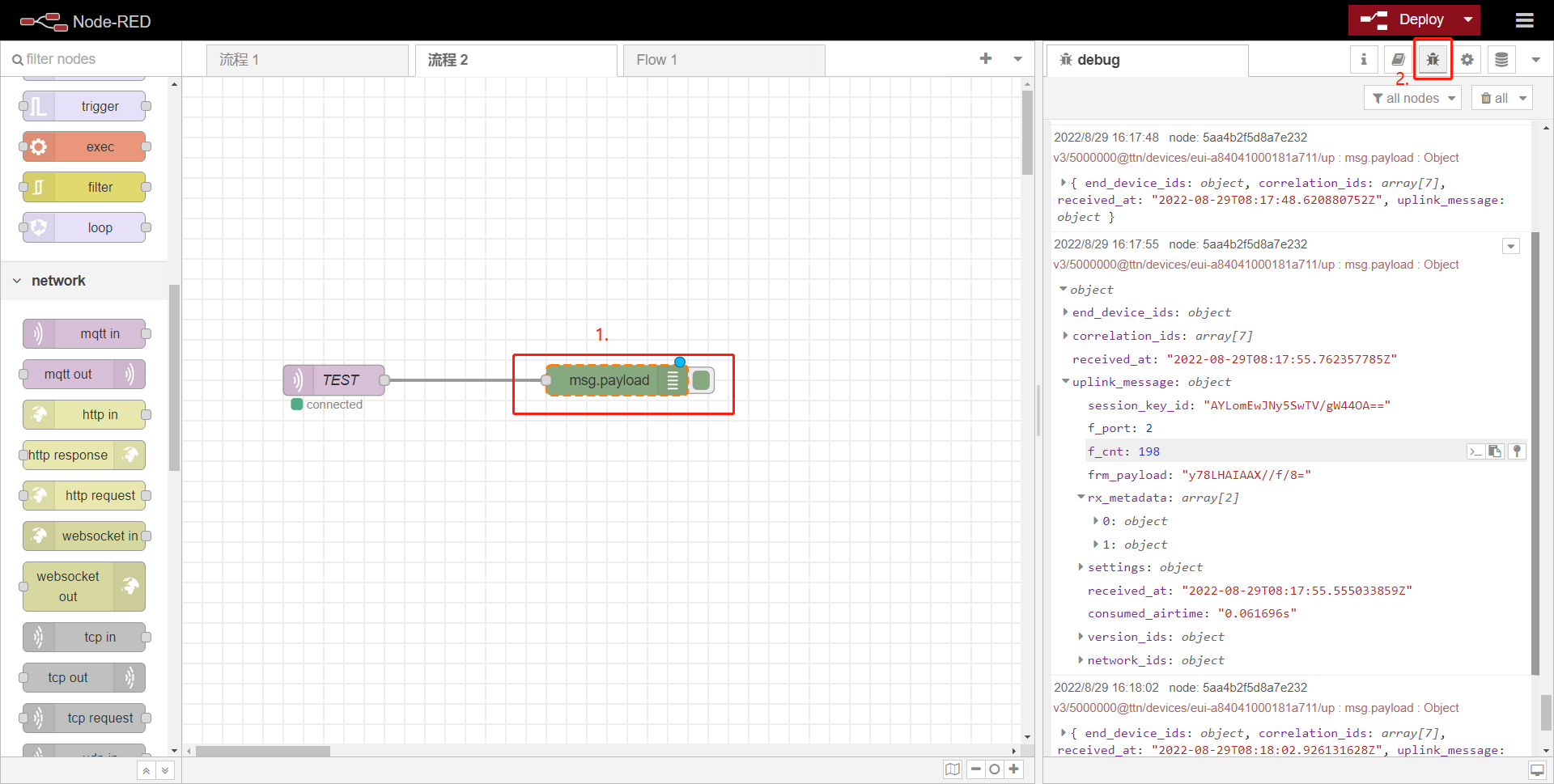
6.2 Debug
Users can check logs by adding debug.
6.3 Example: Use Local Server TTN and Node-Red in LPS8v2
LPS8v2 includes a local TTN Server and Node-Red. This example shows how to configure LHT65N to use with the local Node-Red server. This example assumes users already have:
- LHT65N register on LPS8v2 Built-In TTN server already
- The user is able to see the data on the built-in TTN server device page.
Below are the steps to plot the sensor data on LPS8v2 Node-Red.
6.3.1 Link Node-Red to Local TTN
Users can download the Node-Red decoder from this link and import it into the Node-Red platform: dragino-end-node-decoder/LHT65N.json (github.com)
For more information on importing Input Flow, check out this link: Import Input Flow for Dragino Sensors
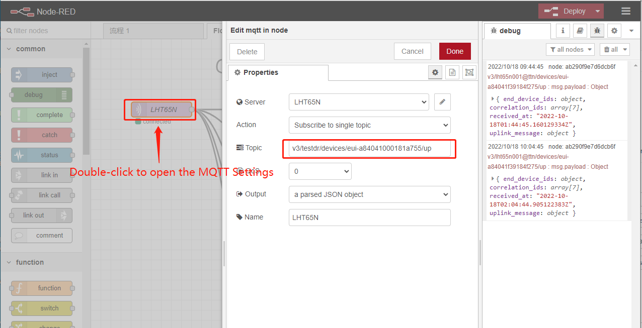
After importing the Input Flow is complete, the user needs to edit the MQTT in the node
1. Change the Topic
Topic modifies it to the following format:
v3/[Application ID]/devices/[End device ID]/up
 [ ]
[ ]
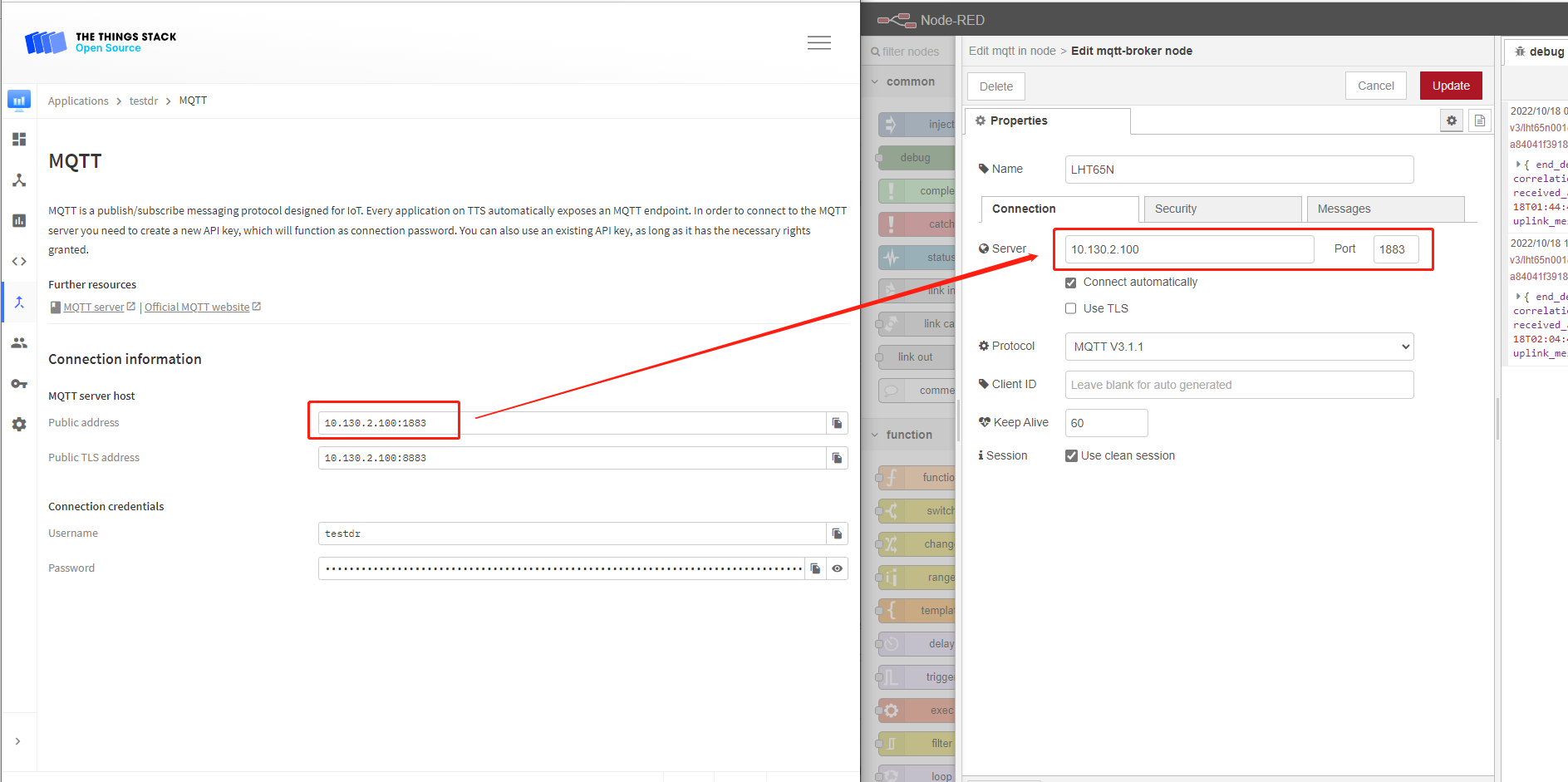
2. Enter the MQTT configuration information
 [ ]
[ ]
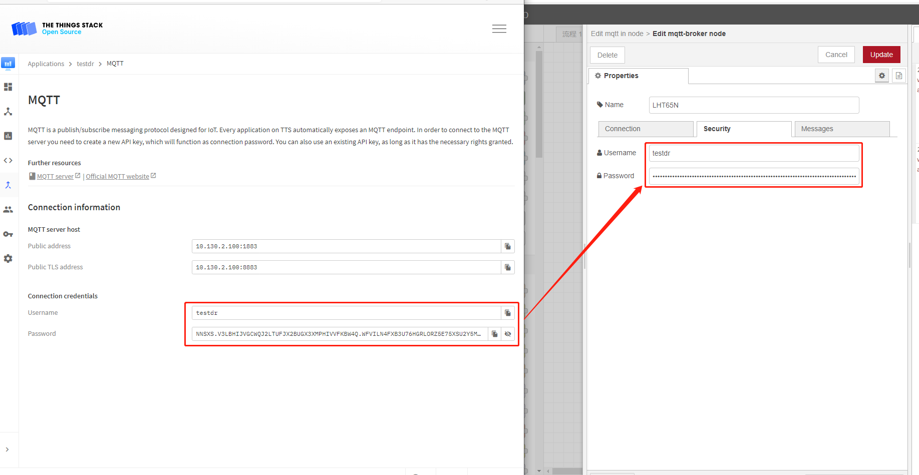
Finally, click "Update" and Deploy
"Connected" indicates that the Link Node-red to Local TTN is normal.
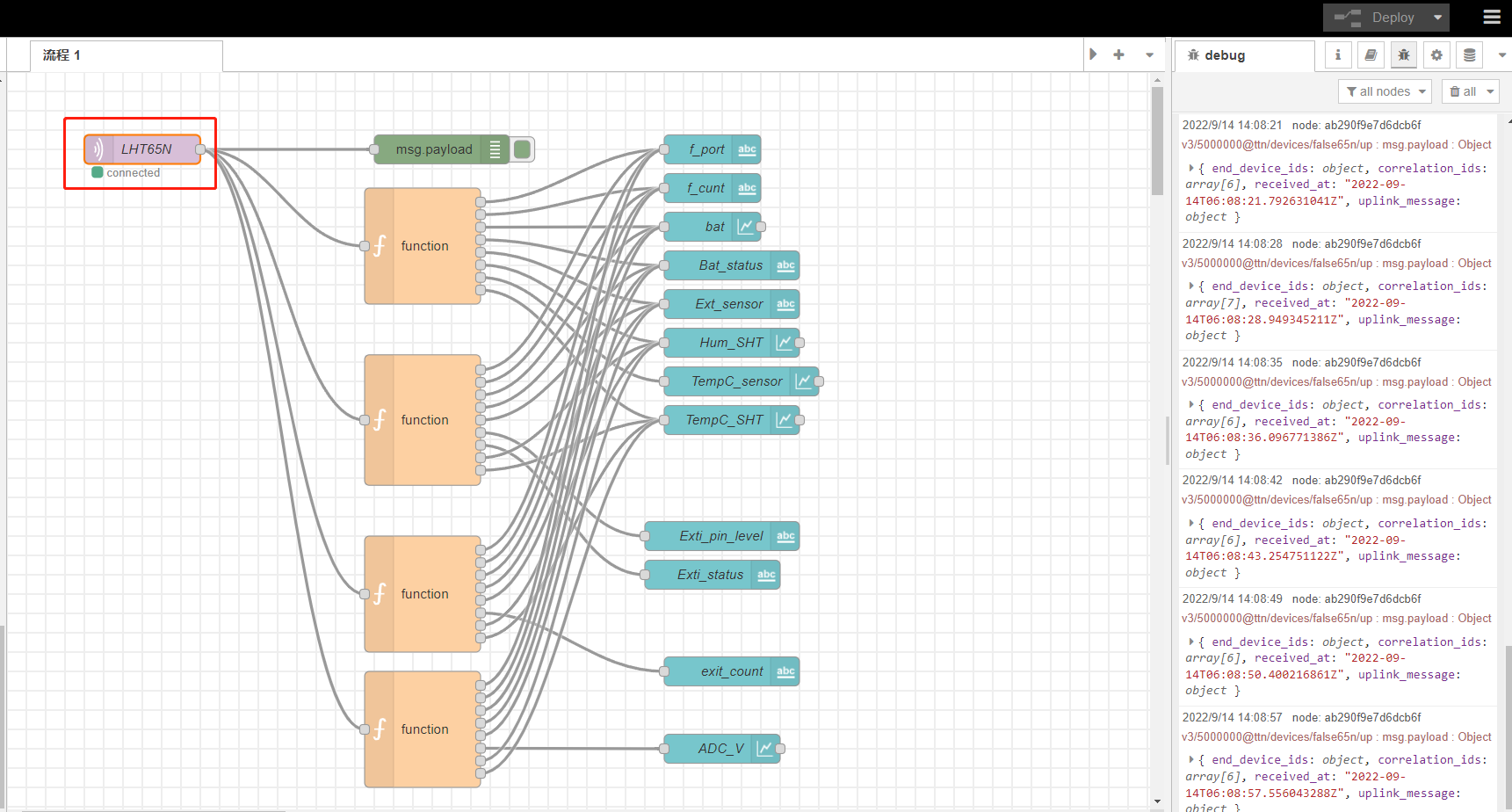
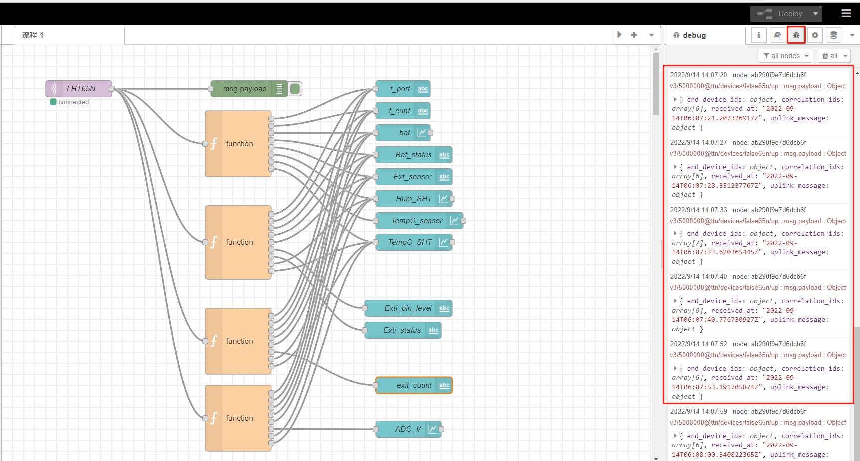
6.3.2 Check result.
Users can check logs by adding debug.
In addition,Users can access the lps8v2 gateway's built-in as server of **Node-Red Chart UI **via the URL([[http://<hostname>:1880/ui or http://<local-IPV4-address>:1880/ui]]{.underline}) in your browser.
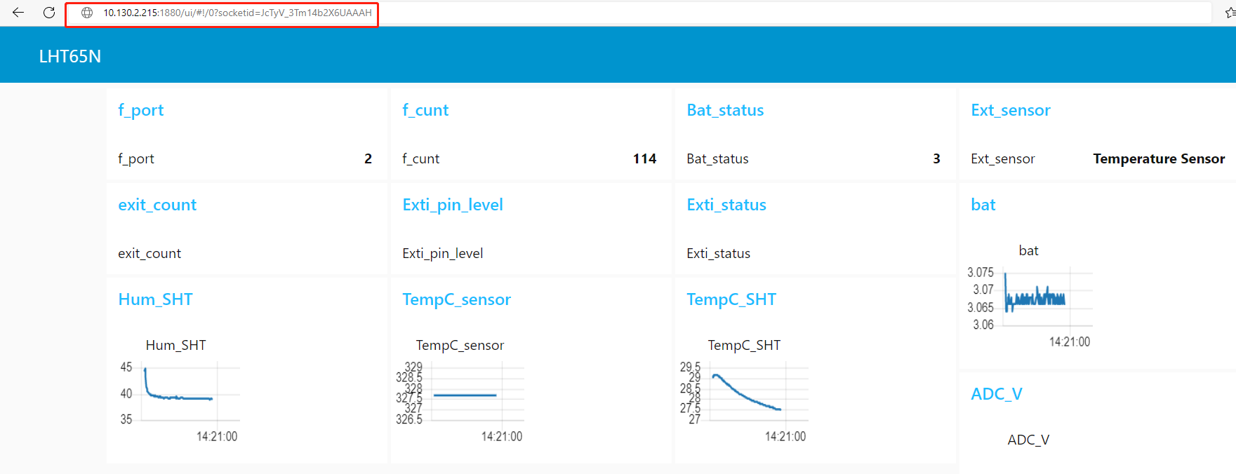 [ ]
[ ]
7. Request Remote Support
These pages are useful to check what is wrong on the Join process. Below shows the four steps that we can check the Join Process.
If problem not solve, and you need dragino remote support, please follow to this document: TTN Support instruction[ If user has checked below steps and still can't solve the problem, please send us (support @ dragino.com) the screenshots for each step to check. They include:]
-
End node is connected to serial port to show the Join frequency and DR. (If possible)
-
Gateway (from gateway UI) traffic to show the packet got from end node and receive from Server. (If possible)
-
Gateway traffic (from server UI) to shows the data exchange between gateway and server. (Normally possible)
-
End Node traffic (from server UI) to shows end node activity in server. (Normally possible)
-
End Node Keys screen shot shows in end node and server. so we can check if the keys are correct. (In most case, we found keys doesn't match, especially APP EUI)
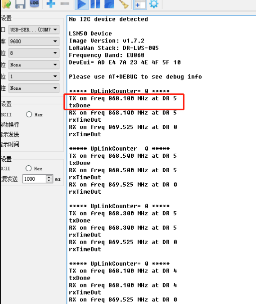
1. End Device Join Screen shot, we can check:
-
If the device is sending join request to server?
-
What frequency the device is sending?
 {#Iimage-20220526141308-33.png .wikigeneratedid xwiki-translated-attribute-_mstalt="453778"}
Console Output from End device to see the transmit frequency
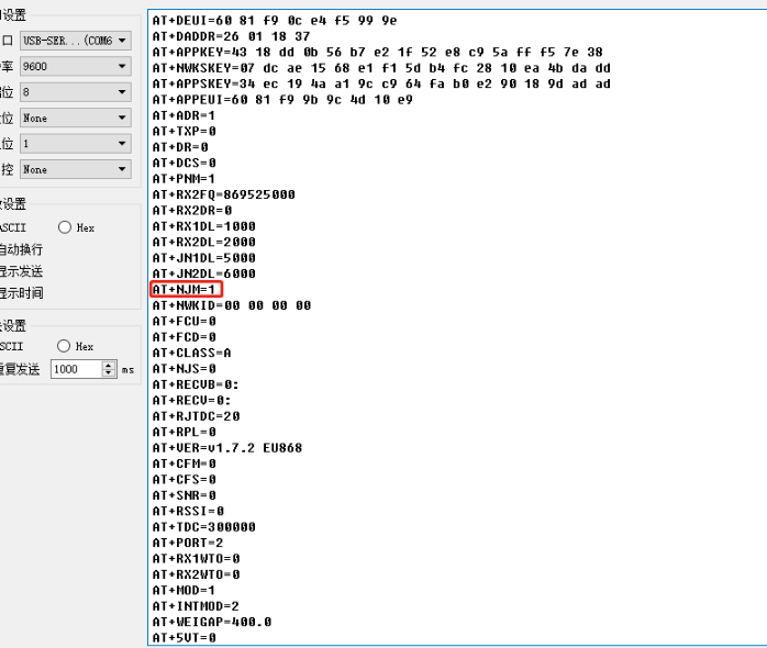
User can run AT+CFGcommand to print configuration information.
- Is the device in OTAA mode or ABP mode?
AT+NJM=1[ ](OTAA mode),AT+NJM=0(ABP mode)
 {#Iimage-20220526141612-36.png .wikigeneratedid xwiki-translated-attribute-_mstalt="454142"}
Console Output from End device to see the transmit frequency
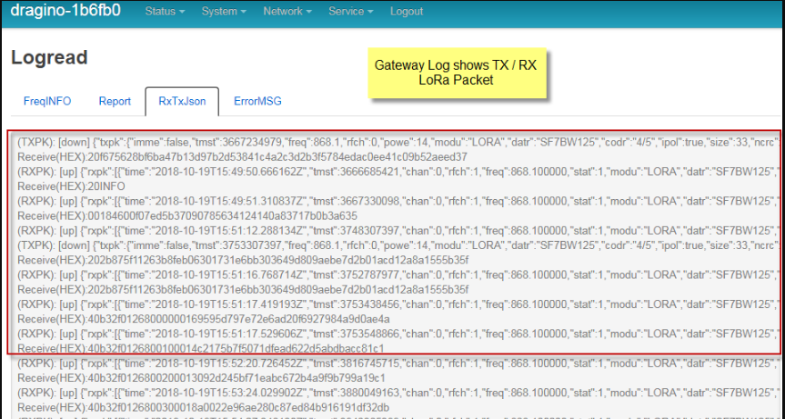
2. Gateway packet traffic in gateway web or ssh. we can check:
-
If the gateway receive the Join request packet from sensor? (If this fail, check if the gateway and sensor works on the match frequency)
-
If the gateway gets the Join Accept message from server and transmit it via LoRa?
::: wikimodel-emptyline :::
 {#Iimage-20220526141739-37.png .wikigeneratedid xwiki-translated-attribute-_mstalt="457847"}
Console Output from Gateway to see packets between end node and server.
3. Gateway Traffic Page in LoRaWAN Server
-
If the Join Request packet arrive the gateway traffic in server? If not, check the internet connection and gateway LoRaWAN server settings.
-
If the server send back a Join Accept for the Join Request? if not, check if the keys from the device match the keys you put in the server, or try to choose a different server route for this end device.
-
If the Join Accept message are in correct frequency? If you set the server to use:
US915、EU868::: wikimodel-emptyline :::
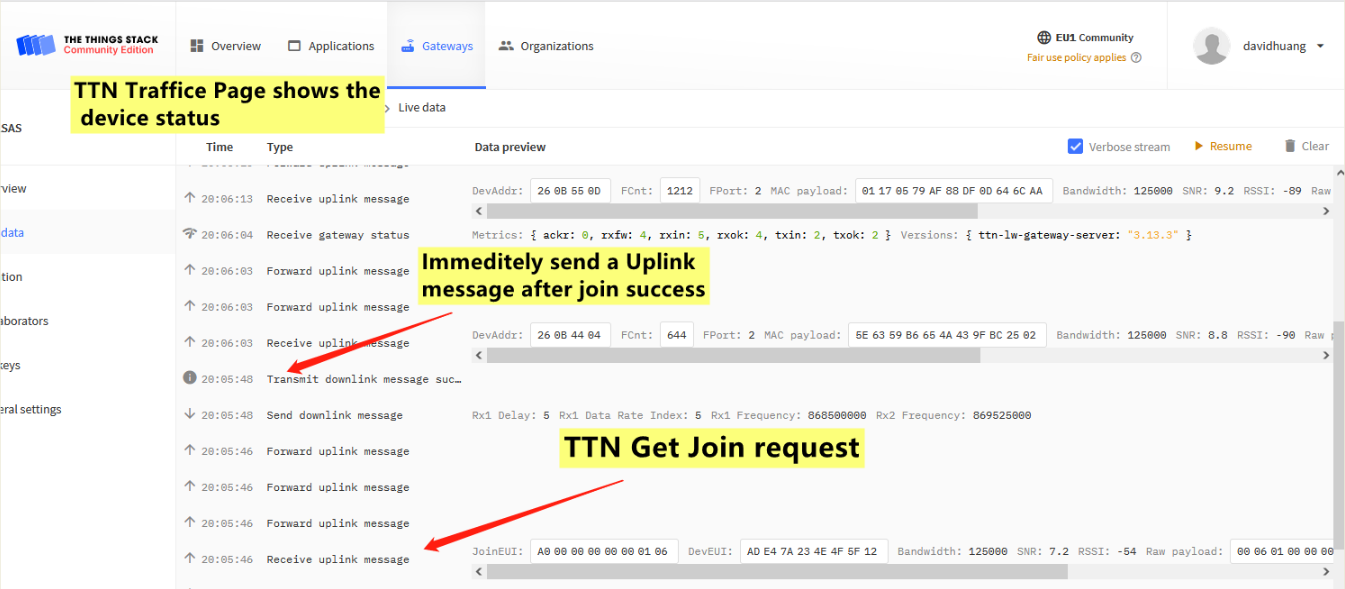
The Traffic for the End node in the server, use TTNv3 as example
 {#Iimage-20220526141917-39.png .wikigeneratedid xwiki-translated-attribute-_mstalt="457899"}
The Traffic for the End node in the server, use TTNv3 as example
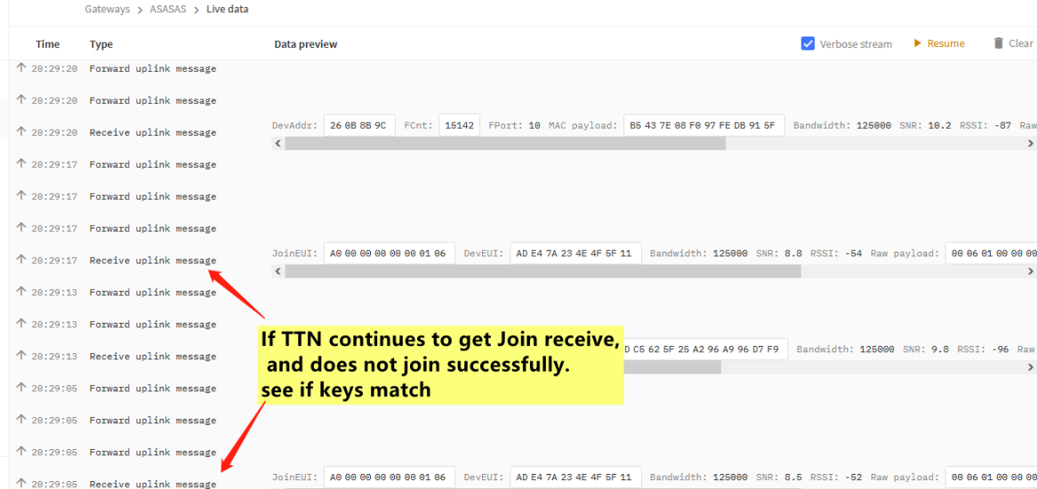
4. Data Page in LoRaWAN server
If this data page shows the Join Request message from the end node? If not, most properly you have wrong settings in the keys. Keys in the server doesn't match the keys in End Node.
 {#Iimage-20220526141956-40.png .wikigeneratedid xwiki-translated-attribute-_mstalt="455832"}
The data for the end device set in server
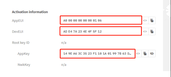 {#Iimage-20220526142033-41.png .wikigeneratedid xwiki-translated-attribute-_mstalt="452036"}
Check if OTAA Keys match the keys in device
8. FAQ
8.1 How to import devices keys to TTN.
For TTS in LPS8v2
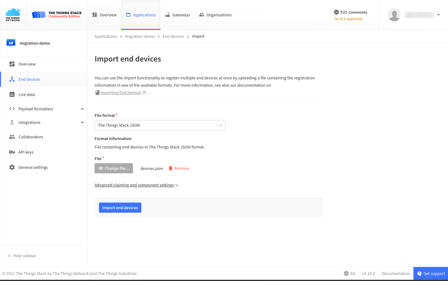
Open your application and click the button Import end devices
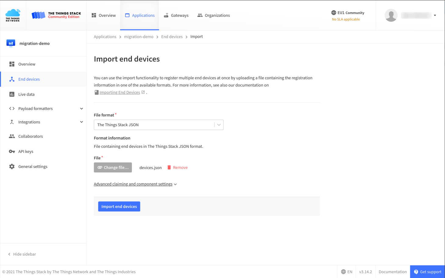
Select the File format and upload the file (e.g. or ).devices/jsondevices.csv
You can specify Fallback values for Frequency plan and LoRaWAN and Regional Parameters version, in case the import file does not specify these settings for the device.
You can also expand the Advanced claiming and component settings to set targeted components, and set the claim authentication code to be generated.
Start the import by clicking the Import end devices button.
Wait for the end devices to be successfully imported. In case any device fails, you will see a relevant error message in the console.
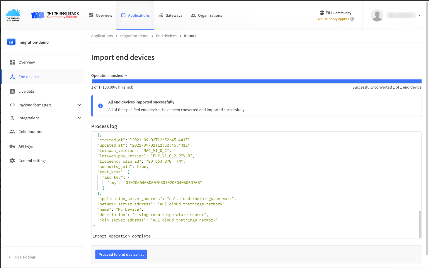
If the import was successful, your devices are added to the list of end devices in your application.
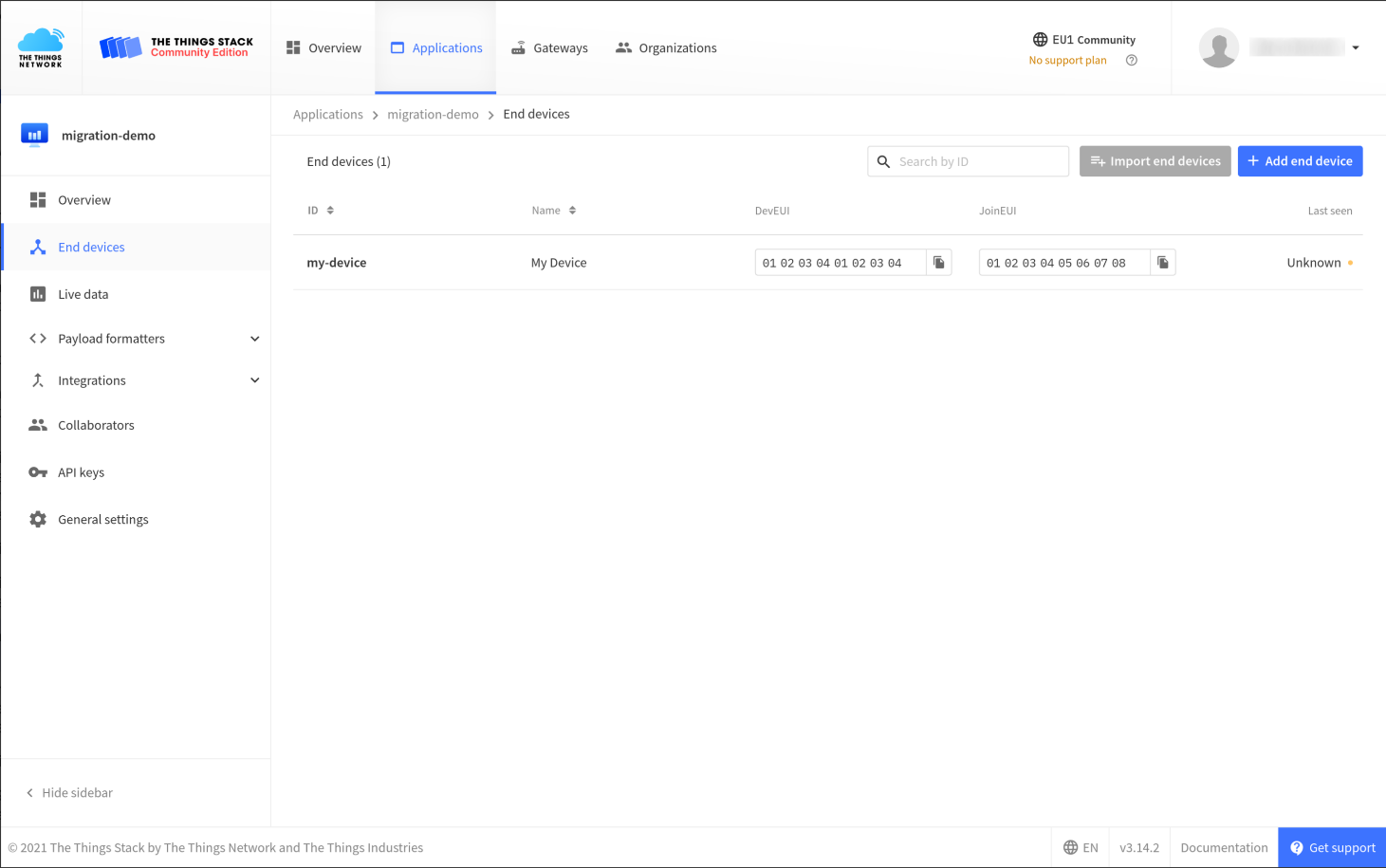
Devices are now registered on The Things Stack.
JSON File Reference
The Things Stack allows you to import end devices from V2, ChirpStack and other LoRaWAN networks using a JSON file describing those devices.
Using JSON file with device descriptions, you can migrate end devices with or without their existing sessions.
Here is an example of an OTAA device description in the file:devices.json
{
  "ids": {
    "device_id": "my-device",
    "dev_eui": "0102030405060708",
    "join_eui": "0102030405060708"
  },
  "name": "My Device",
  "description": "Living room temperature sensor",
  "lorawan_version": "MAC_V1_0_2",
  "lorawan_phy_version": "PHY_V1_0_2_REV_B",
  "frequency_plan_id": "EU_863_870_TTN",
  "supports_join": true,
  "root_keys": {
    "app_key": {
      "key": "01020304050607080102030405060708"
    }
  }
}
Multiple end devices can also be contained in a single file like so:devices.json
{
  /* device 1 */
}
{
  /* device 2 */
}
The format above is considered by the Console and CLI as a JSON stream, processing one object at a time. For more details in how to use the file
CSV File Reference
The Things Stack has support for importing end devices from CSV (comma-separated values) files. This is useful when batches of end devices are managed in Microsoft Excel or any other spreadsheet or database that can export to CSV file.
The CSV import in The Things Stack uses the following settings:
-
Semicolon () as field delimiter. This makes working with Microsoft Excel and other spreadsheets convenient;
-
Header row is required
-
On each row, the same number of fields as on the header line
-
Use quotes to use in a field value;
-
Use double quotes to escape quotes
-
Unknown header columns are permitted and ignored
-
Name and id cannot have capital letters and special characters
-
Example column lorawan_phy_version is not needed
[ ]
Example
Minimal example:
dev_eui;join_eui;frequency_plan_id;lorawan_version;lorawan_phy_version;app_key
1111111111111111;1111111111111111;EU_863_870_TTN;MAC_V1_0_4;RP002_V1_0_3;11111111111111111111111111111111
2222222222222222;2222222222222222;EU_863_870_TTN;MAC_V1_0_4;RP002_V1_0_3;22222222222222222222222222222222
3333333333333333;3333333333333333;EU_863_870_TTN;MAC_V1_0_4;RP002_V1_0_3;33333333333333333333333333333333
All columns for a LoRaWAN 1.0.4 device:
id;dev_eui;join_eui;name;frequency_plan_id;lorawan_version;lorawan_phy_version;brand_id;model_id;hardware_version;firmware_version;band_id;app_key
test-one;1111111111111111;1111111111111111;Device 1;EU_863_870_TTN;MAC_V1_0_4;RP002_V1_0_3;the-things-industries;generic-node-sensor-edition;1.0.4;1.0;EU_863_870;11111111111111111111111111111111
test-two;2222222222222222;2222222222222222;Device 2;EU_863_870_TTN;MAC_V1_0_4;RP002_V1_0_3;the-things-industries;generic-node-sensor-edition;1.0.4;1.0;EU_863_870;22222222222222222222222222222222
test-three;3333333333333333;3333333333333333;Device 3;EU_863_870_TTN;MAC_V1_0_4;RP002_V1_0_3;the-things-industries;generic-node-sensor-edition;1.0.4;1.0;EU_863_870;33333333333333333333333333333333
[ ]
Excel Template
Download the Excel template. You can remove all columns that are not required (see above).
8.2 How to download and analyze End Device's log?[ ]
1. Get information about a single node
Download this file in the node's live data interface
2. Get information about the entire Application
Click the "See all activity" button on the main interface of the application
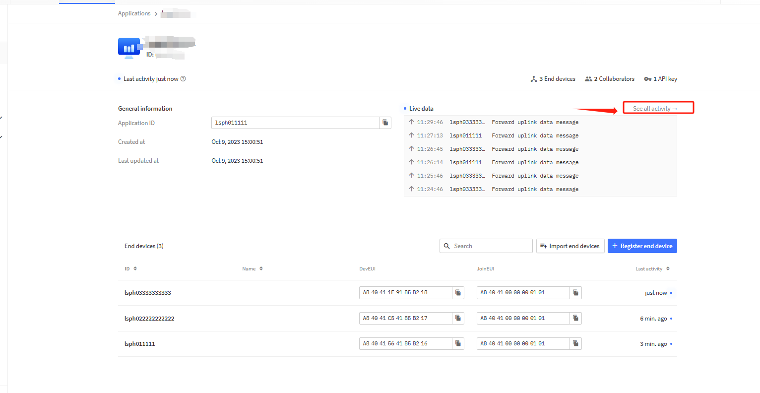
Download this file in application live data interface
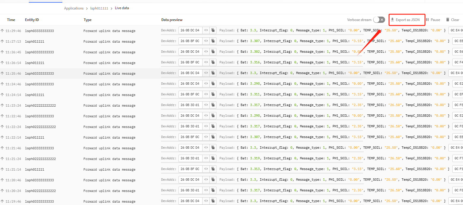
After the data collection is completed, you can send this file directly to our technical support personnel for analysis.
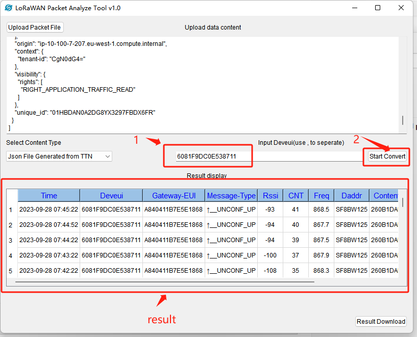
You can also use the packet analysis tool developed by our company to check it yourself. Please refer to the following link to use this tool.
9. Trouble Shooting.
9.1 How to solve the problem of MIC Mismatch?
Please refer to the link below:
http:///docs/wiki/Configuration/end-node/lorawan-debug/
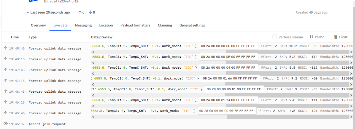
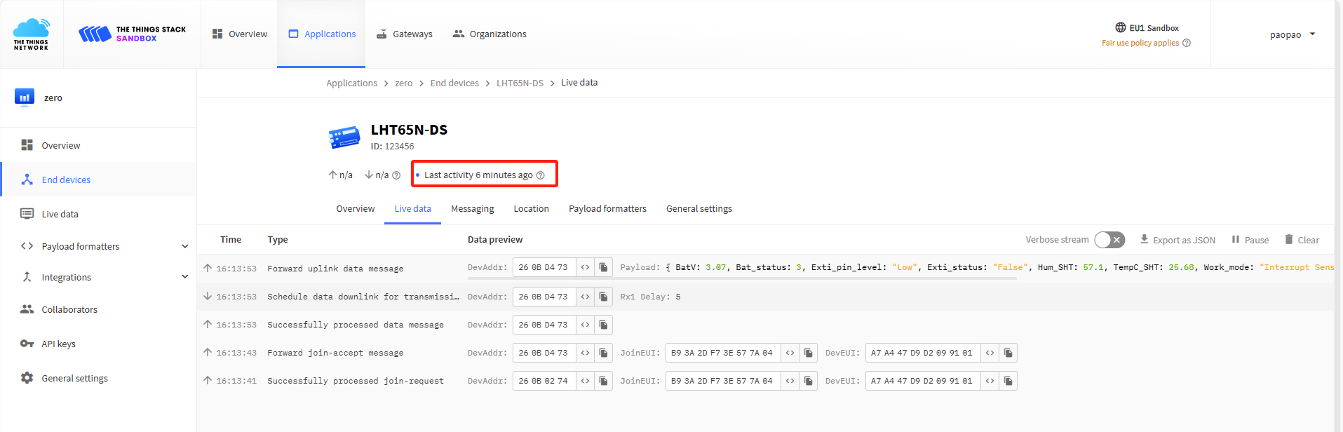
9.2 Why node join succeeds but detailed data cannot be observed in the live data interface?
The live data interface on the TTN platform is more orientated towards real-time observations, so if you don't click on the observations in time, you will not be able to see the previous details if you click on the interface again after a period of time.
TTN has no fixed official explanation for how long this data refreshes, but actual tests show it to be around 10 minutes.
Users can see the time of the last activity of a node inside one of the Applications:
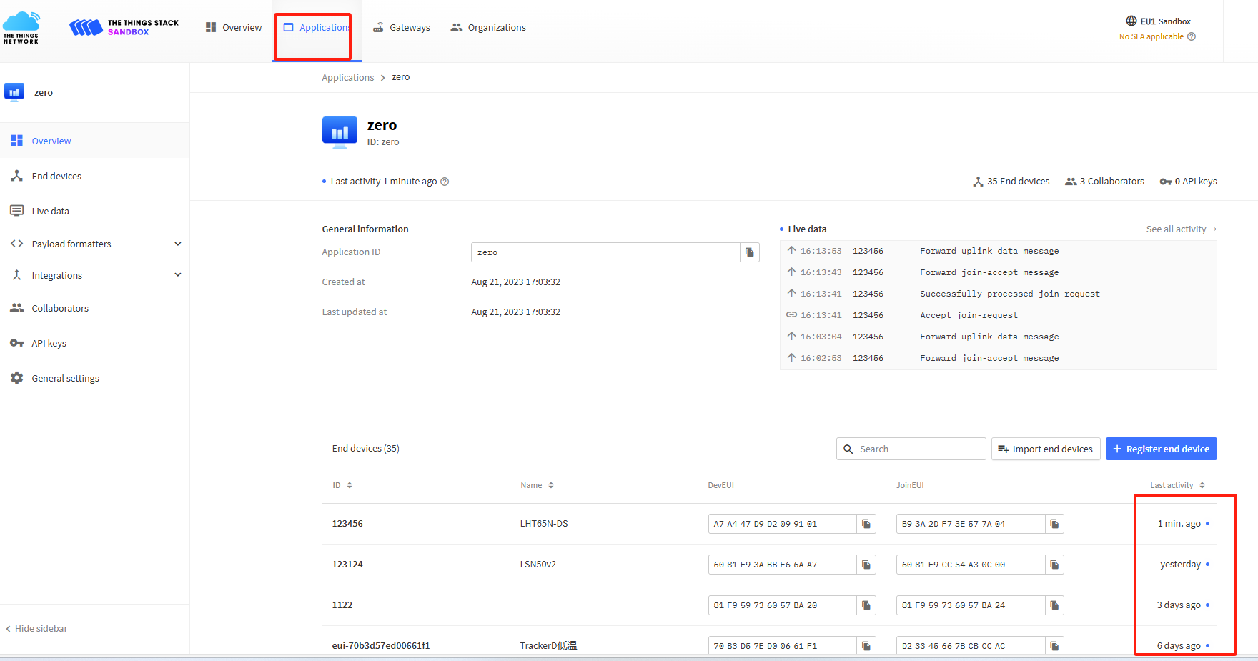
For example:
- After 6 minutes of the last activity, click on the live data interface to observe the data.
- The last activity of a node that has not been clicked for a long time was more than ten minutes ago, and you cannot observe the previous detailed data by clicking on the live data interface at this time.
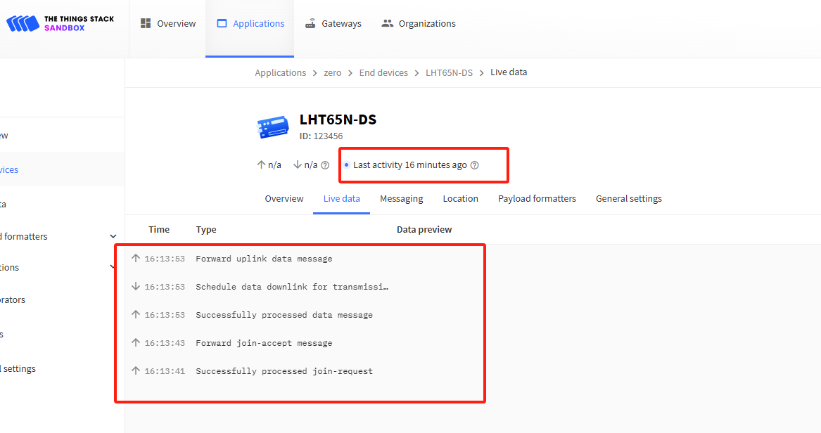
In addition, if one stays in the LIVE DATA screen for a node, several previous details have been observed. If the node is inactive for a long time to come, and the interface is refreshed at this point, the details of the previously active data may be refreshed and no longer displayed.
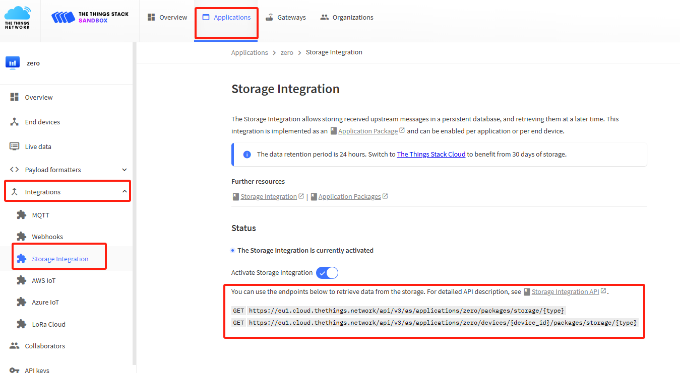
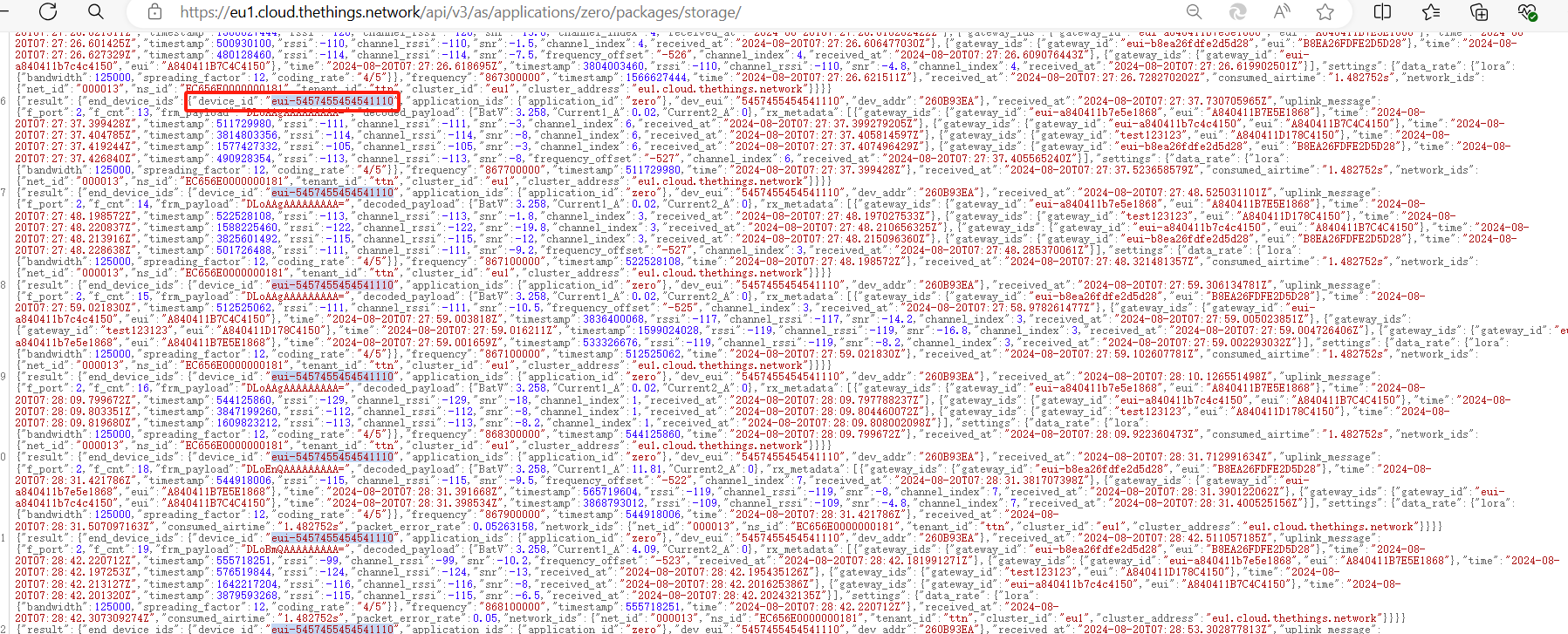
If the user needs to view the data uplinked from a previous node, the data can be retrieved through the endpoint given by Storage Integration. The data can then be distinguished between different nodes based on device_id.
::: like-container