Can I use an external power adapter or solar panel?
1. Can I use an external power adapter or solar panel to power motherboard?
The motherboard of the equipment is equipped with an 8500mAh Battery by default. To set the device to a short uplink interval such as 1 minutes uplink interval. This 8500mAh battery is not enough for long time use.
**[It is possible to power device via external Power. ][There are two ways :]
1.1 Powering the Device via an 3.3V External Power Supply (for LB / NB / CB Models)
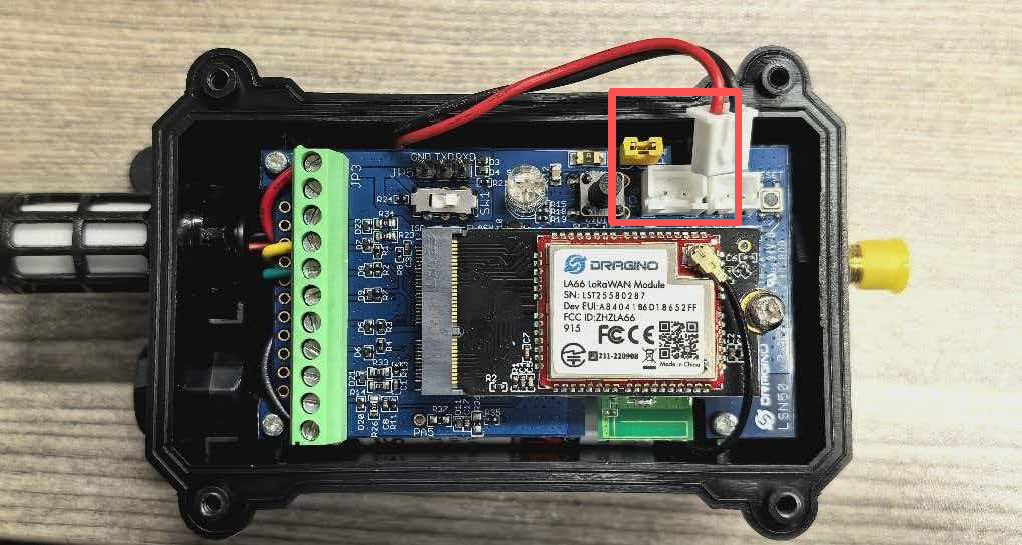
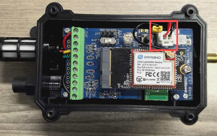
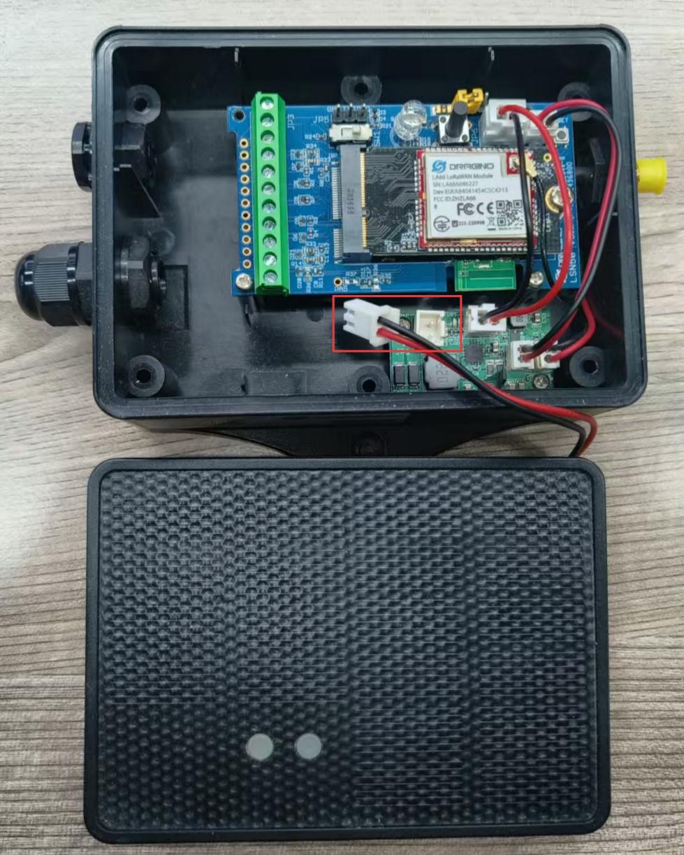
As shown below, the motherboard is by default power by 8500mAh battery via the battery cable.
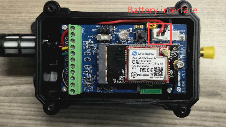
User can remove the cable here and connect the external 3.3v DC power to this connector.
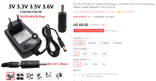
Recommand Spec for the power adapter:
- Output: 3.0 ~ 3.6v DC
- Output Current: >500mA
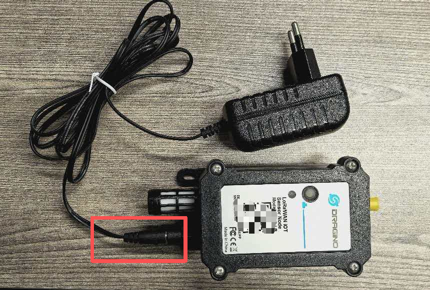
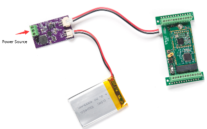
Example photo for external 3.3v DC power** ([Users can also consult Dragino to purchase a ready-made external 3.3v DC power])**[.]
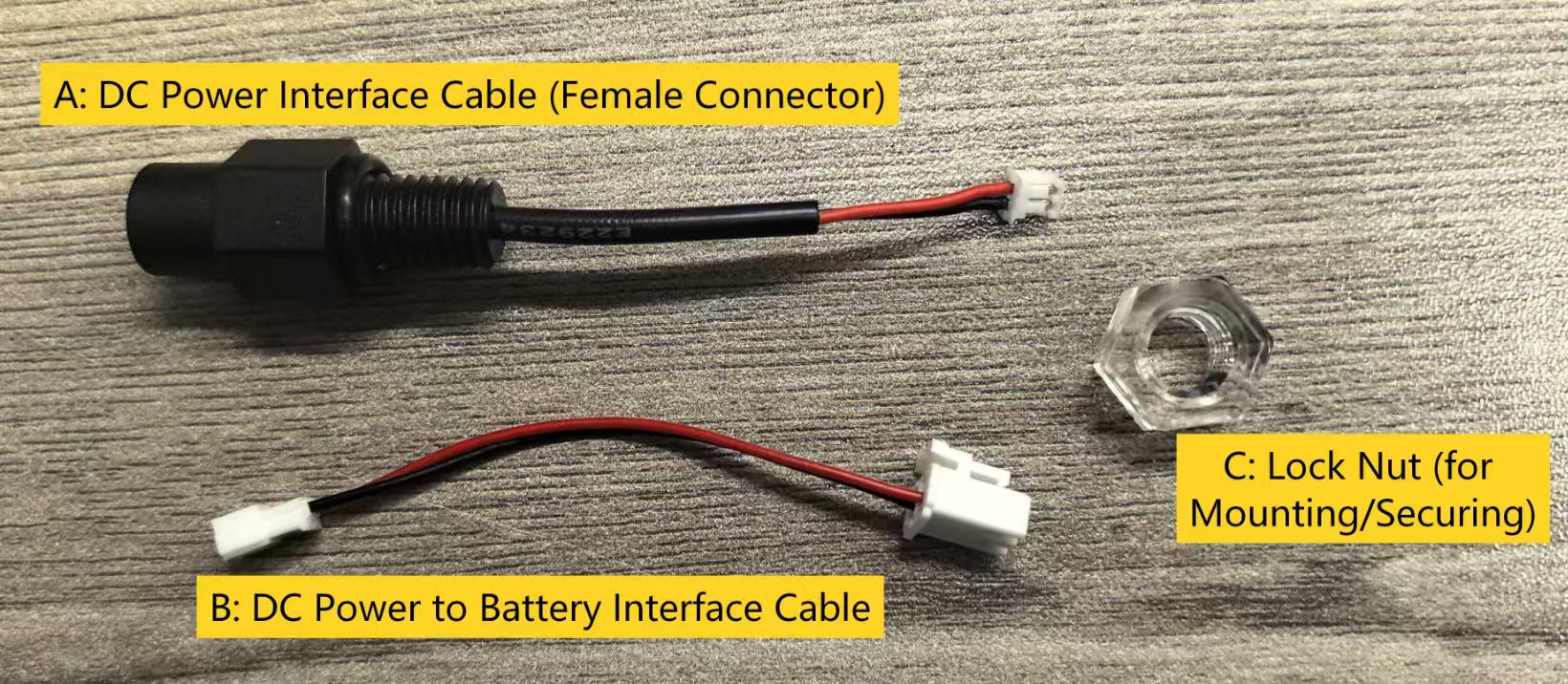
Step 1: Obtain the DC Power Accessory Contact Dragino to acquire the official DC power accessory kit.
The kit includes:
Step 2: Prepare the Device for Wiring
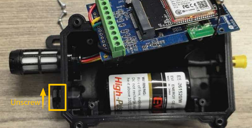
① Open the device enclosure and disconnect the battery from the motherboard.
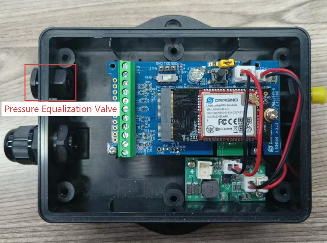
② Remove the motherboard from the enclosure. Prepare to replace the original pressure equalization valve with the DC power accessory.
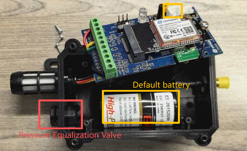
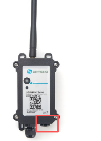
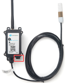
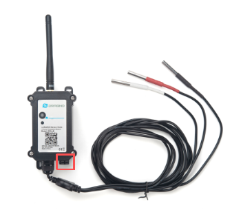
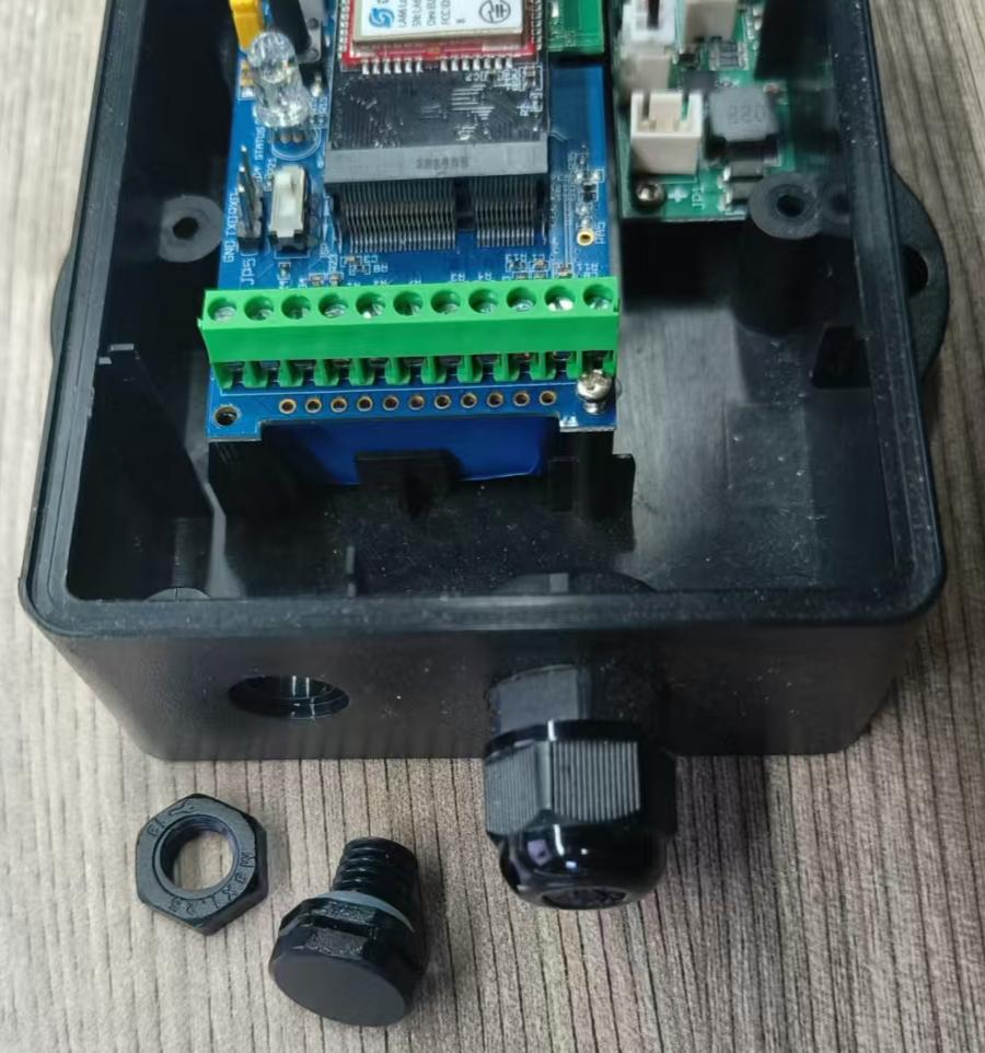
Step 3: Replace the Pressure Equalization Valve with the DC Power Accessory
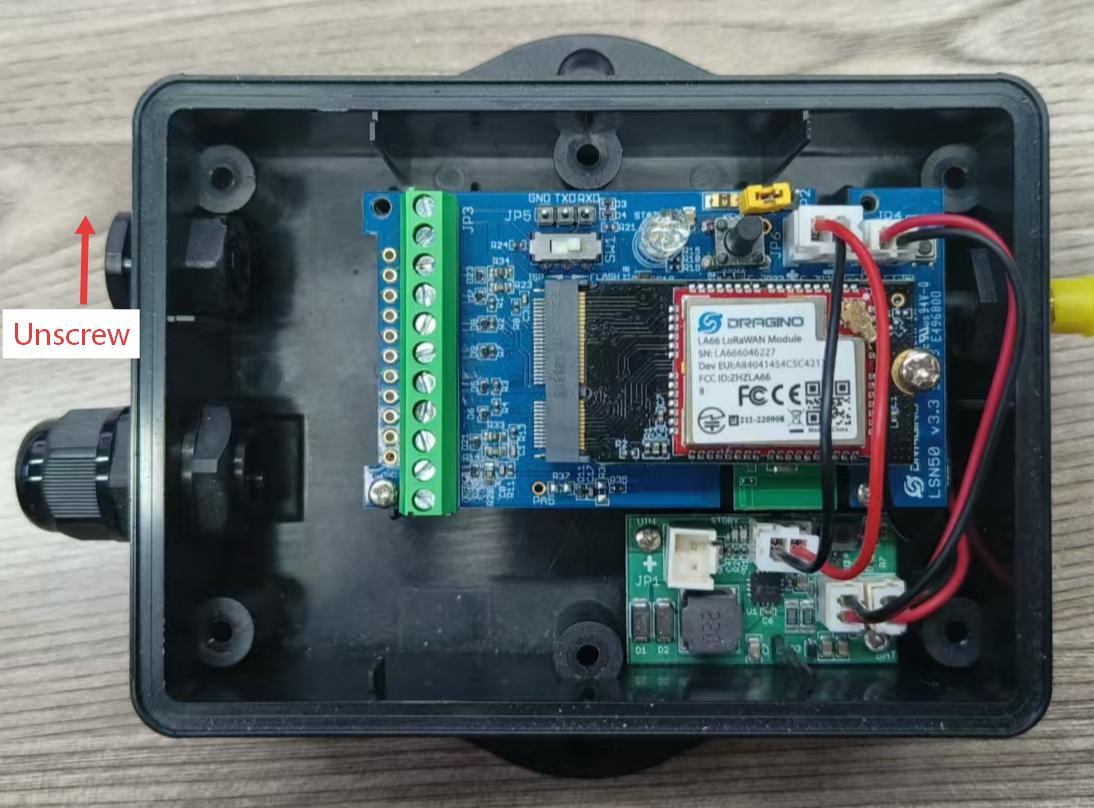
- Unscrew and remove the original pressure equalization valve in the direction shown in the diagram.(The default battery can be removed to facilitate subsequent installation.)
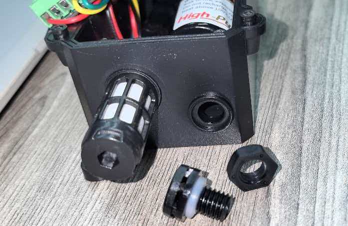
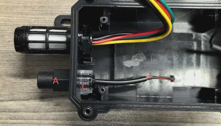
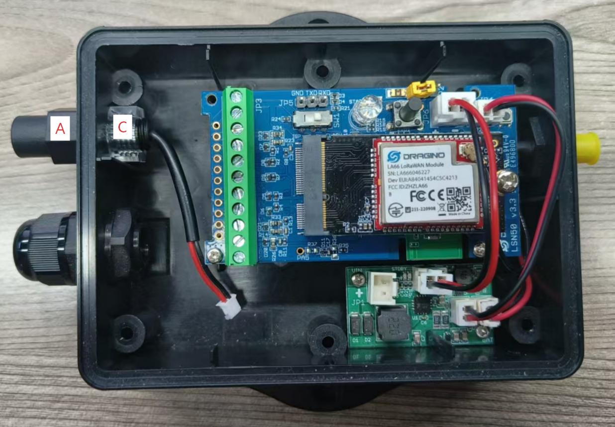
- First, place Part C (Lock Nut) inside the original valve port position, with its larger opening facing outward.
- Then insert Part A (DC Power Interface Cable) from the outside into the valve port. Finally, secure Part A from the inside by tightening Part C firmly.
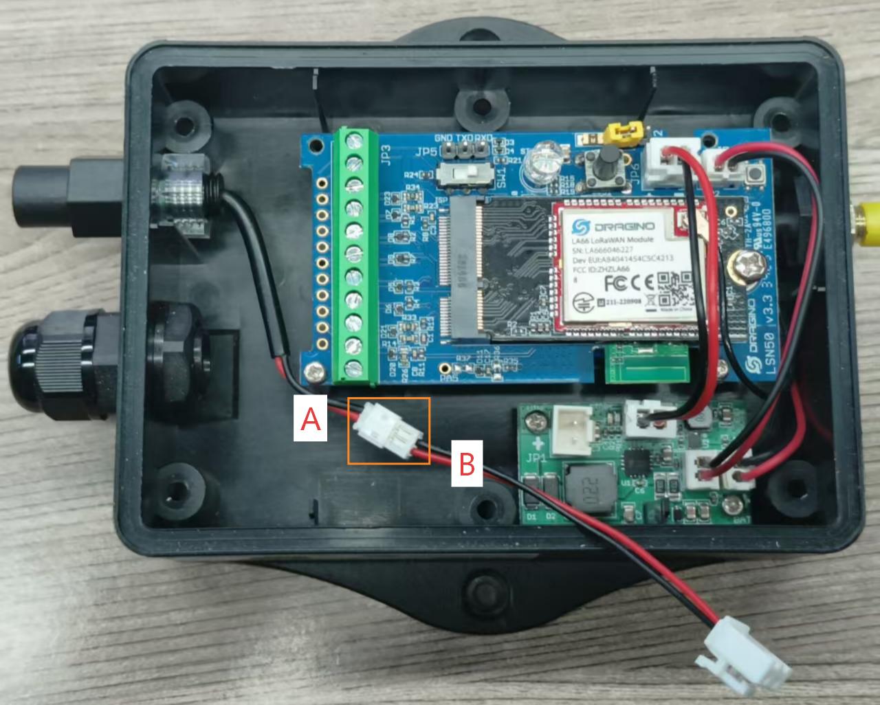
- Connect Part B (DC Power to Battery Interface Cable) to the interface of Part A.
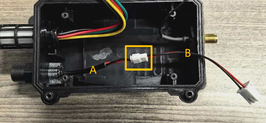
- Finally, connect the white connector of Part B (compatible with the battery interface on the motherboard) to the battery port on the motherboard. Then reinstall the motherboard back into the enclosure.
Step 4: Complete the Connection
- Close the device enclosure (note the position of the AT button).
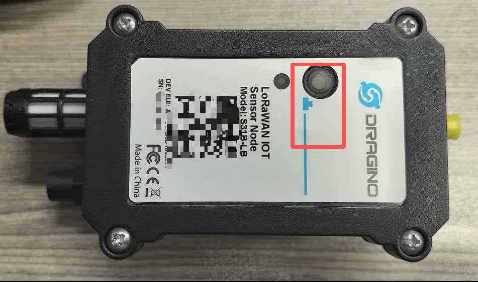
- Then plug the male connector of the external 3.3V DC power supply into the female connector of Part A on the outside of the device.
1.2 Powering the Device via an 5~12v External Power Supply (for LS / NS / CS Models)
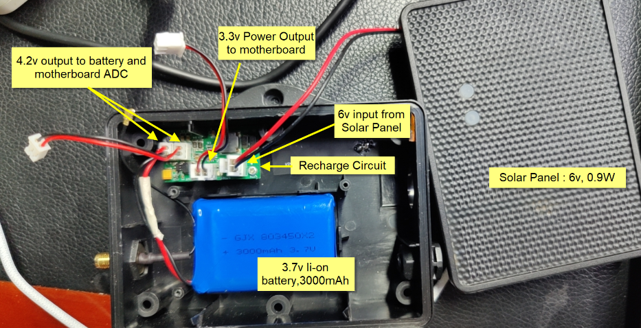
As shown in the figure below, the motherboard is powered by a regulated 3.4V supply provided by the solar panel by default.
The battery is rated at 3.7V and 3000mAh under default conditions.
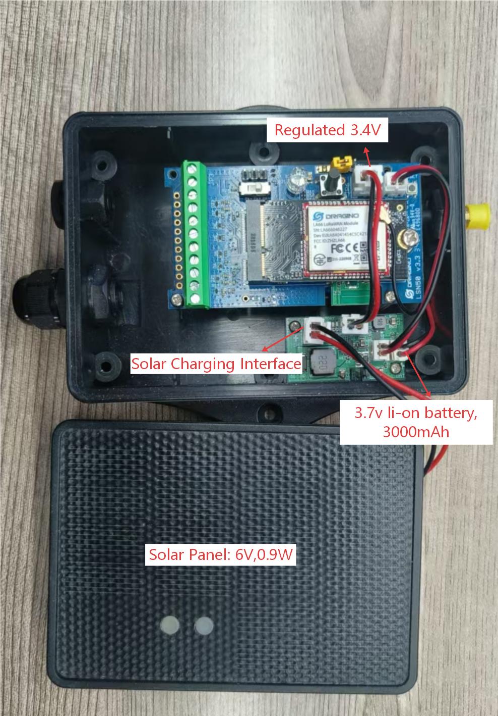
Users can disconnect the solar panel cable from the solar charging port and connect an external 5v~12v DC power source to that port.
Recommand Spec for the power adapter:
- Output: 5v ~ 12v DC
- Output Current: 1A
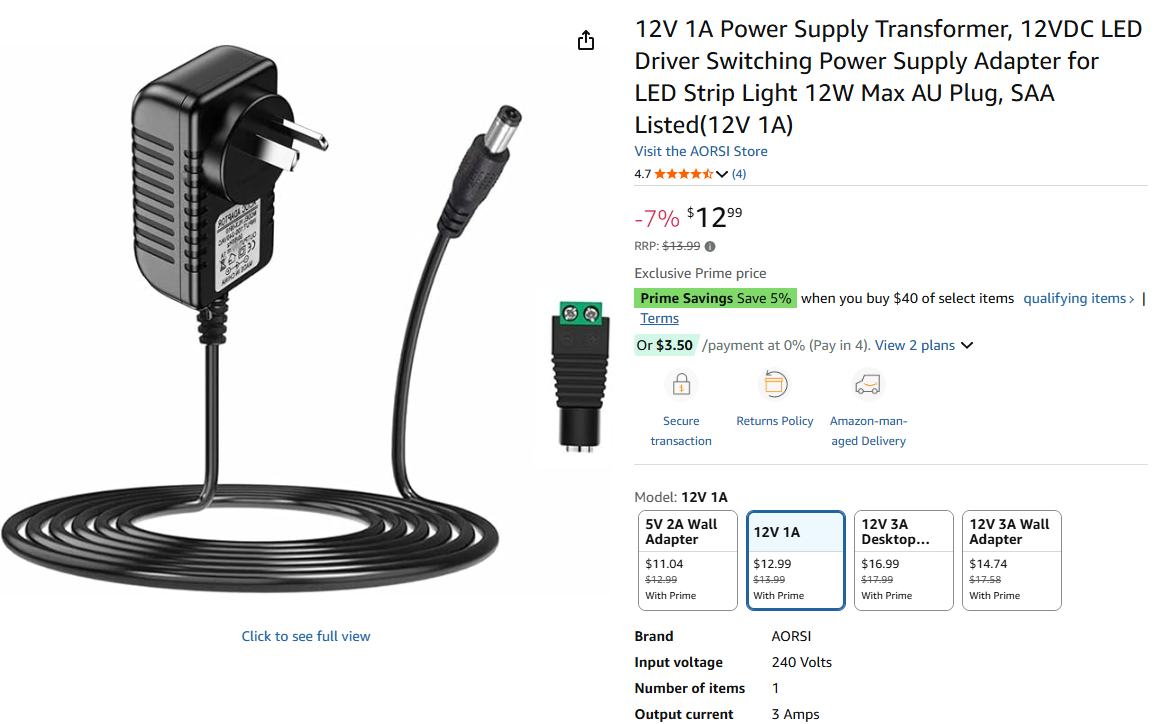
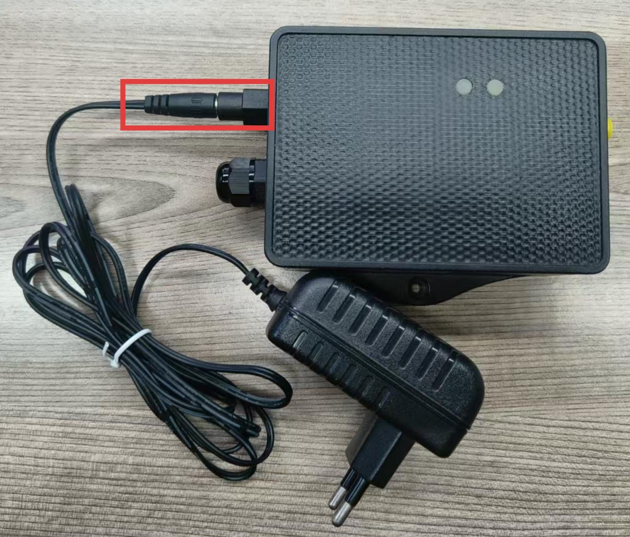
Example photo for external 12v DC power** ([Users can also consult Dragino to purchase a ready-made external 12v DC power])**[.]
Step 1: Obtain the DC Power Accessory Contact Dragino to acquire the official DC power accessory kit.
The kit includes:
Step 2: Prepare the Device for Wiring
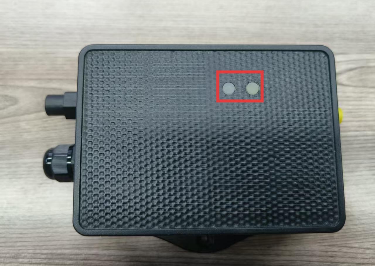
① Open the device housing and disconnect the solar panel from the solar charging board.
② Prepare to replace the original pressure equalization valve with the DC power accessory.
Step 3: Replace the Pressure Equalization Valve with the DC Power Accessory
- Unscrew and remove the original pressure equalization valve in the direction shown in the diagram.
- First, place Part C (Lock Nut) inside the original valve port position, with its larger opening facing outward.
- Then insert Part A (DC Power Interface Cable) from the outside into the valve port. Finally, secure Part A from the inside by tightening Part C firmly.
- Connect Part B (DC Power to Battery Interface Cable) to the interface of Part A.
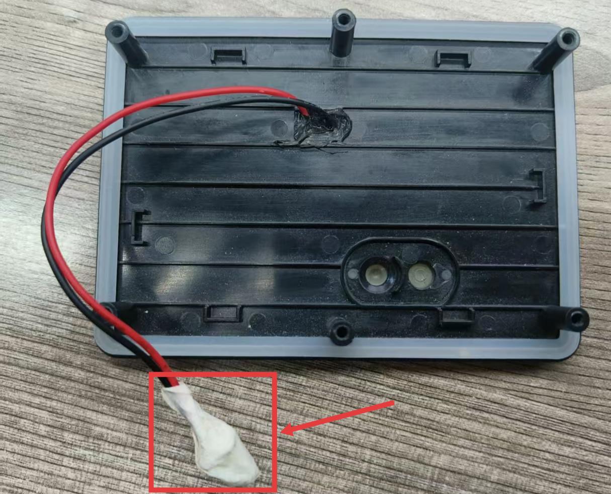
- Finally, connect the white connector on Component B to the solar panel port on the green charging panel.
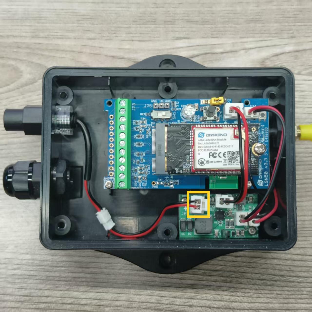
Note: The power cable for the solar panel is not required, so it can be cut off or retained and concealed within the housing. However, ensure short-circuit prevention measures are taken by sealing the cable connectors with insulating tape. As shown below:
Step 4: Complete the Connection
- Close the device enclosure (note the position of the AT button).
- Then plug the male connector of the external 5~12v DC power supply into the female connector of Part A on the outside of the device.
1.3 Use the Dragino Solar Recharge Kit with external 5~12v DC
[http:///docs/wiki/FAQs/general/battery-life-calculation/)
1.4 Power it via 12v solar panel and add rechargeable battery
Dragino has a recharge kit for this purpose. User can see this link for reference:
https://shop.dragino.com/index.php?rt=product/product&product_id=126
1.5 Water Proof Notice:
Note: Both options mean an extra cable needs to pass throug the enclosure. In the current enclosure, the best is to drill a hole on the enclosure to pass and use glue to fill it for outdoor use purposes.
::: like-container