Add a GPS Module to Dragino End Node
1. GPS Module Introduction
Note: This explanation uses the UP-18F GPS module as an example.
1.1 Pin Description
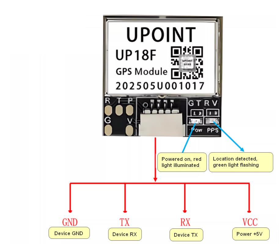
1.2 Features
- Chip: u-blox UBX-M10050-KB
- Frequencies: GPS L1, QZSS L1 C/A/S, GLONASS L1, BeiDou B1I/B1C, Galileo E1B/C, SBAS
- L1 C/A: WAAS, EGNOS, MSAS, GAGAN
- Baud Rate: 4800 bps--921600 bps (Default: 115200 bps)
- Horizontal Accuracy: 2.0 m CEP 50% 2D RMS with SBAS augmentation (under clear sky conditions)
- Time Accuracy: RMS: 30 ns
- Maximum Operating Altitude: 50,000 m
- Maximum Velocity: 500 m/s
- Refresh Rate: 1Hz~10Hz (Default: 10Hz)
- Operating Temperature: -40°C ~ +85°C
- Storage Temperature: -40°C ~ +85°C
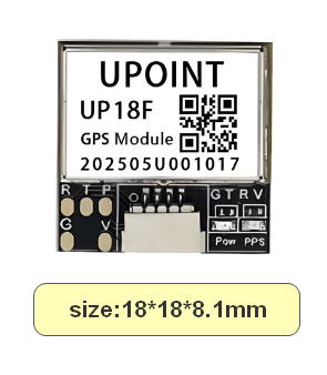
1.3 UP-18F Dimensions
2. Applicable hardware versions
Note:
This GPS module communicates via the UART protocol. Therefore:
- 1. When the device connects to external sensors via the UART protocol, this GPS module cannot be used;
- 2. Devices employing the RS485 sampling protocol cannot simultaneously operate using both UART and RS485 protocols by default. Consequently, when the device connects to external sensors via the RS485 protocol, this GPS module cannot be used.
2.1 LSN50v3.3 Motherboard Wiring Method
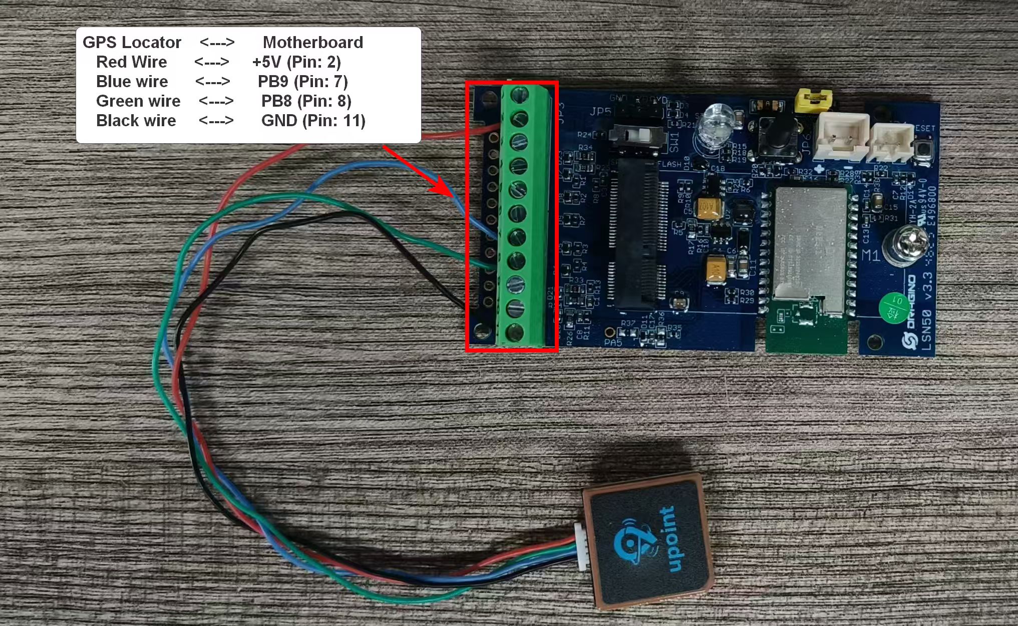
GPS Locator <---> Motherboard
Red Wire <---> +5V (Pin: 2)
Blue wire <---> PB9 (Pin No.: 7)
Green wire <---> PB8 (Pin No.: 8)
Black wire <---> GND (Pin No.: 11)
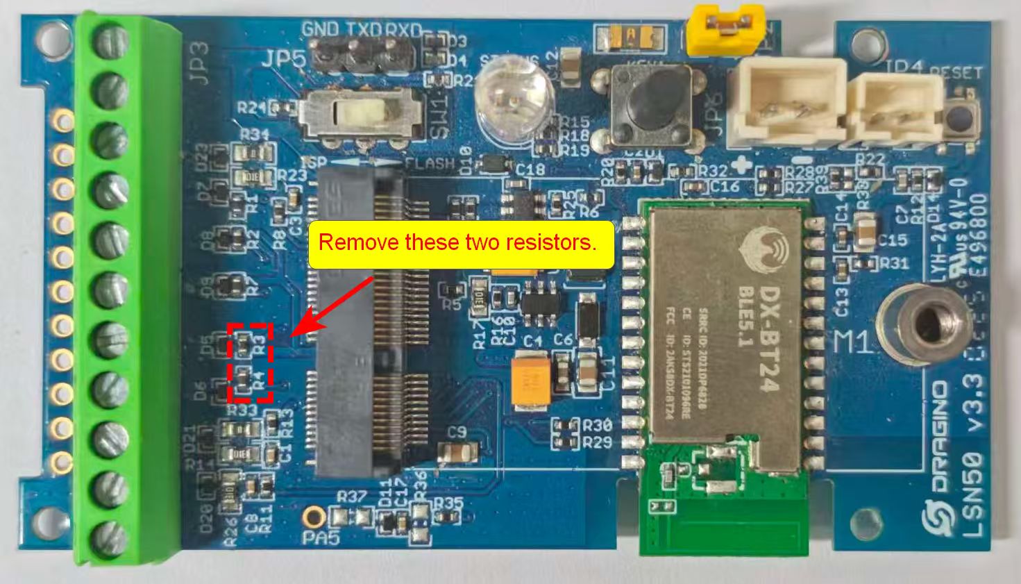
Note: Note: When using the LSN50v3.3 motherboard, remove the two resistors labeled "R3" and "R4" from the motherboard. Failure to remove these resistors will increase the motherboard's sleep power consumption.
2.2 RS485-BL v2.1 Motherboard Wiring Method
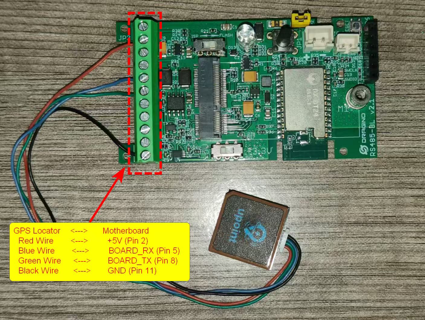
GPS Locator <---> Motherboard
Red Wire <---> +5V (Pin 2)
Blue Wire <---> BOARD_RX (Pin 5)
Green Wire <---> BOARD_TX (Pin 6)
Black Wire <---> GND (Pin 11)
3. Command Description
Note: 1. Currently, only the KS and KN versions have this feature. 2. Three AT commands have been added, applicable only to MQTT JSON downlink. 3. The three commands currently apply only to GPS positioning modules using serial port protocols.
3.1 Positioning Accuracy Configuration
Function: Get or set GPS positioning accuracy settings
AT Command: AT+GPSSETTING=a.b,c (Default value AT+GPSSETTING=3.5,0``
- a,b: GPS positioning accuracy. The smaller this value, the more accurate the positioning, but the longer the search time.(Value range: 0.0 to 25.5)
- c: Whether to use the previous valid value when invalid latitude and longitude coordinates are obtained by GPS positioning.
For example:
AT+GPSSETTING=3.5,0//GPS positioning accuracy, invalid positioning will not use the previous valid value.AT+GPSSETTING=3.0,1//GPS positioning accuracy, invalid positioning will use the previous valid value.
Downlink Format: Note: This command is only valid for the JSON downstream format of the MQTT transport protocol.
- {"Config":"[
AT+GPSSETTING=3.5,0\]\"
3.2 Location Duration Configuration
Function: Get or set GPS positioning interval in units of hours.
AT Command: AT+GTDC=aa,bb,cc
- aa: Enable or disable GPS positioning
- bb: GPS positioning search time, in seconds
- cc: GPS positioning interval, in hours
For example:
AT+GTDC=0,120,24//Disable GPSAT+GTDC=1,120,24//Enable GPS, GPS positioning search time 120 seconds, GPS positioning interval 24 hoursAT+GTDC=1,60,12//Enable GPS, GPS positioning search time 60 seconds, GPS positioning interval 12 hours
Downlink Command: Note: This command is only valid for the JSON downstream format of the MQTT transport protocol.
- {"Config":"[
AT+GTDC=1,120,24\]\"
3.3 SOS Mode
Function: Enables or disables SOS alarm mode, value 0-255, unit: minutes.
AT Command: AT+GPSSOS=xx
- xx: Location Alarm Interval (value: 0--255, unit: min)
For example:
AT+GPSSOS=0//Disables SOS alarm mode.AT+GPSSOS=3//Immediately enables GPS positioning and sends a packet, then sends a location alarm every 3 minutes.
Downlink Command: Note: This command is only valid for the JSON downstream format of the MQTT transport protocol.
- {"Config":"[
AT+GPSSOS=3\]\"
::: like-container