OTA Update Firmware for NB-IoT/LTE-M end node
1. Overview
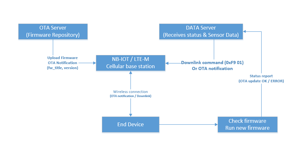
*Figure: OTA Network Architecture*
This document describes the Over-the-Air (OTA) firmware update functionality for Dragino NB-IoT/LTE-M end nodes. The OTA feature enables remote firmware updates without physical access to the device, significantly reducing maintenance costs and improving deployment flexibility.
2. Hardware Prerequisites and Identification
This chapter describes the supported product series for OTA firmware updates and how to identify whether your device hardware is compatible.
2.1 Supported Product Series
This OTA firmware update guide applies to the following Dragino NB-IoT / LTE-M product series:
Series
Network Type
Description
Example Models
-NB, -NS, -NB2
NB-IoT
NB-IoT end nodes (BC660K-GL module)
S31-NB, S31-NS, S31-NB2, RS485-NB, RS485-NS, RS485-NB2 ...
-CB, -CS, -CB2
LTE-M / Cat-M1
LTE-M end nodes (BG95-M2 module)
S31-CB, S31-CS, S31-CB2, RS485-CB, RS485-CS, RS485-CB2 ...
Other Series:
NB-IoT, LTE-M / Cat-M1
-N: NB-IoT end nodes
-C: LTE-M end nodes
WSC2-N, POM01-N
WSC2-C, POM01-C
Warning
Important Note: OTA functionality requires external SPI Flash hardware on the device. For details on how to identify Flash-capable devices, please refer to Section 2.3.
2.2 Hardware Requirement: External SPI Flash
OTA functionality requires an external SPI Flash (4MB) on the device.
- MCU: STM32L0xx series (Cortex-M0+)
- External Memory: SPI Flash (4Mb, for new firmware storage)
- Communication Module: Quectel NB-IoT/LTE-M module (supports MQTT/CoAP/UDP/TCP)
- Sensor: Depends on device model (e.g., SHT31 temperature and humidity sensor for S31-NB)
2.3 How to Identify Hardware Version
This section helps you determine whether your device has the SPI Flash hardware required for OTA updates.
2.3.1 By Product Label / Serial Number
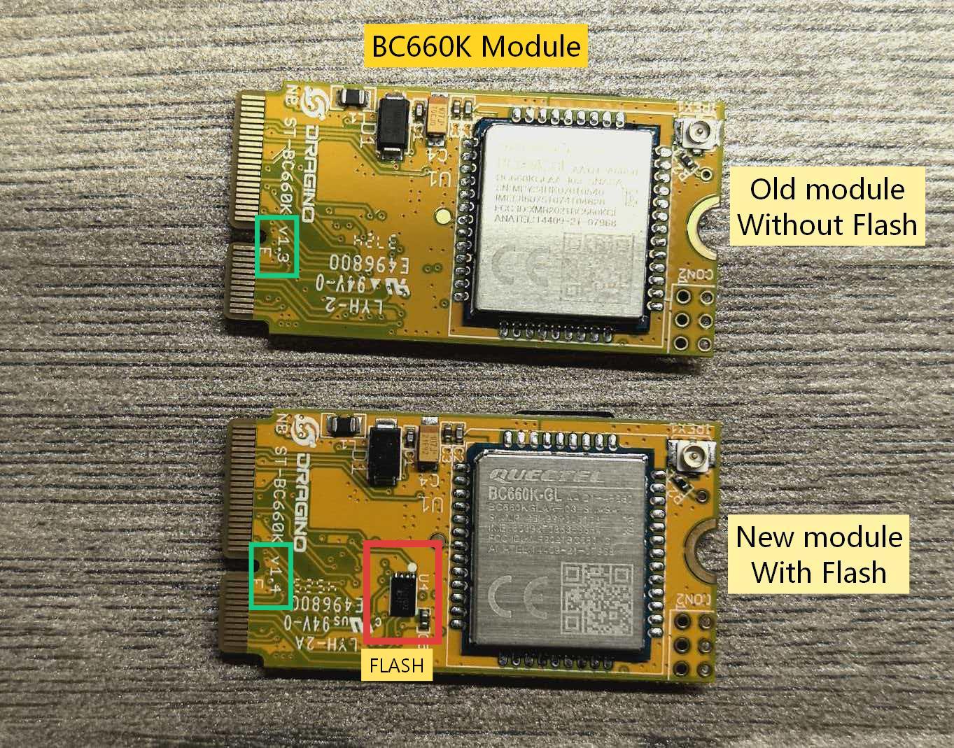
NB-IoT Series (BC660K-GL module):
Serial Number Range
Flash Status
BC660GL26110001 and above
WITH 4MB Flash (OTA capable) Below BC660GL26110001
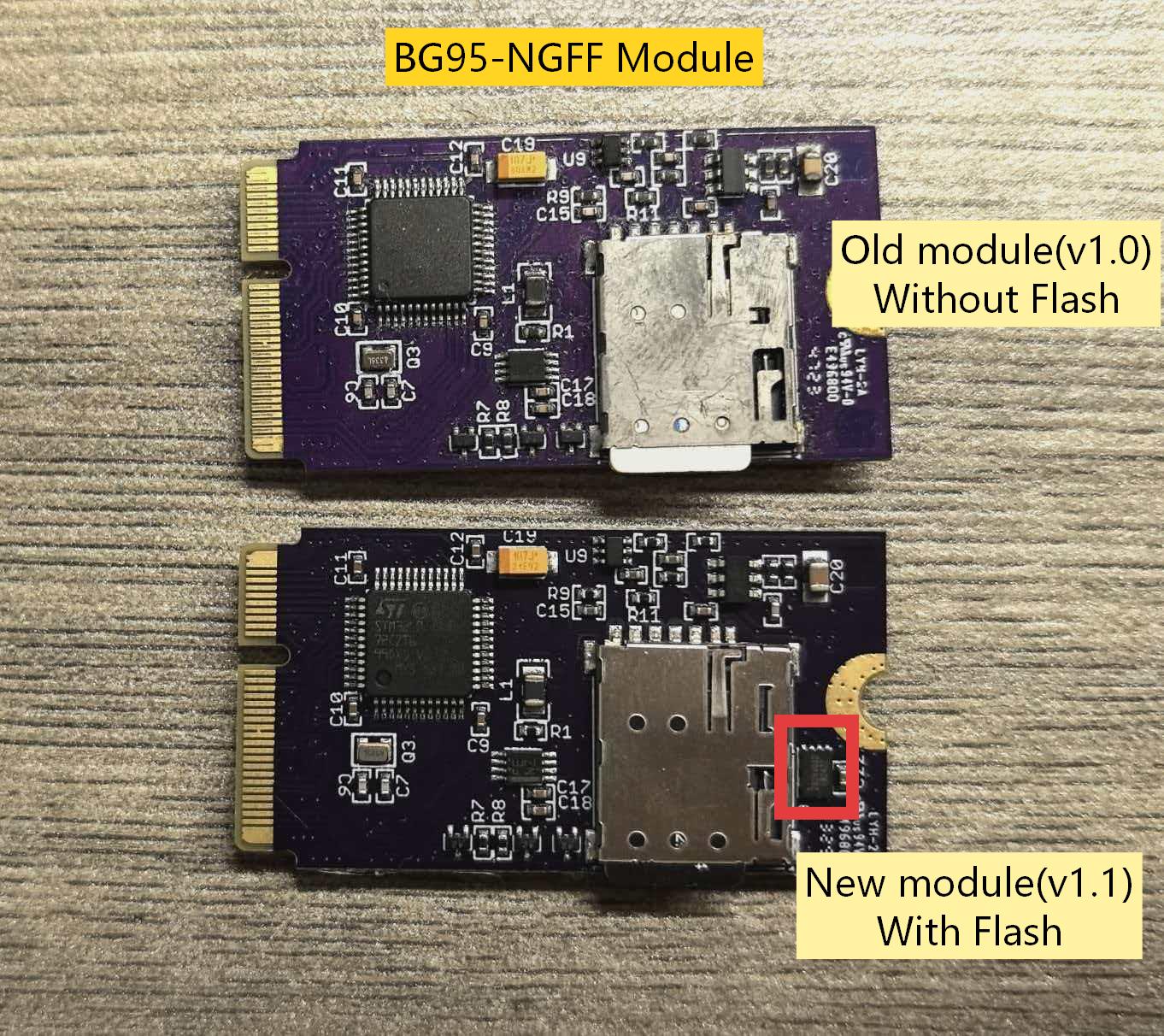
WITHOUT Flash (OTA not available) LTE-M Series (BG95-M2 module):
Serial Number Range
Flash Status
BG95-M226120001 and above
WITH 4MB Flash (OTA capable) Below BG95-M226120001
WITHOUT Flash (OTA not available)
Warning
Important Note: Devices with serial numbers at or after the threshold must use new firmware (with Flash support) to avoid abnormal power consumption.
2.3.2 By Physical Inspection
- With Flash: PCB has 8-pin SOIC chip
- Without Flash: No Flash chip present in the designated footprint
3. Hardware Compatibility Matrix
This section explains the compatibility between firmware versions and hardware configurations.
3.1 Firmware and Hardware Compatibility
Firmware Version
Hardware WITHOUT Flash
Hardware WITH Flash
Old Version (none ota / flash support)
Compatible - Normal operation
NOT Compatible - High power consumption - Battery drains quickly
New Version (OTA Support)
Safe but OTA not available - Reports "Hardware not supported" error
Fully Compatible - OTA updates work correctly
3.2 Detailed Scenarios
Scenario A: OTA Firmware + Hardware WITHOUT Flash
- Behavior: Device safely rejects OTA commands
- Error Code: 2 ("Hardware not supported")
- Impact: Normal sensor operation unaffected
- Action: The device is still usable, but users need to use the original update method—BLE or UART connection—for firmware updates.
Scenario B: Old Firmware (No OTA) + Hardware WITH Flash
- Behavior: Software does not recognize Flash hardware
- Impact: HIGH POWER CONSUMPTION - Battery drains rapidly
- Risk: Device may become unusable within days/weeks instead of years
- Action: Must upgrade to OTA-capable firmware immediately
Scenario C: OTA Firmware + Hardware WITH Flash
- Behavior: Full OTA functionality available
- Impact: Optimal performance and power efficiency
- Action: Use OTA updates as described in this document
4. Software Requirements
Before initiating an OTA update, ensure the following conditions are met:
- Device has external SPI Flash (check section 2.3 How to Identify Hardware Version )
- Device is properly powered and connected to the NB-IoT network
- Current firmware version supports OTA functionality
- New firmware file (.bin format) is prepared and uploaded to the OTA server
- Access to an MQTT-based OTA server (Dragino OTA server)
5. OTA Server Configuration
Before triggering an OTA update, the device must be configured with the OTA server connection parameters using AT commands.
NB/CB series devices support the following configuration methods:
-
AT Command via Bluetooth Connection: BLE Configure Instruction.
-
AT Command via UART Connection: UART Connection
Select the appropriate method to connect to your device and configure the OTA parameters using the AT commands below.
For detailed instructions on setting up an OTA server (ThingsEye Platform or Custom MQTT Server), please refer to: OTA Server Setup Guide for NB-IoT/LTE-M End Nodes
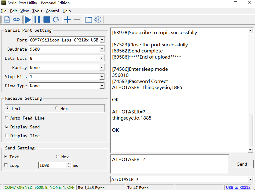
5.1 Configure OTA Server Address
AT+OTASER=<server\_address>,<port>
Parameters:
- server_address: OTA server domain name or IP address
- port: Server port (typically 1883 for MQTT)
Take Thingseye as an example: AT+OTASER=thingseye.io,1885
Warning
Note: The ThingsEye platform has fixed the MQTT connection port for the MQTT-OTA feature to 1885.
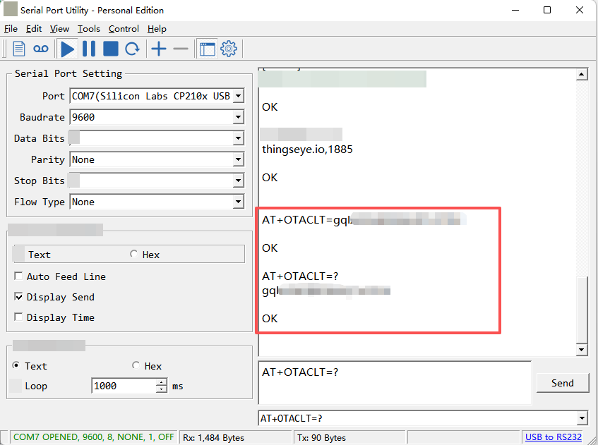
5.2 Configure Client ID
AT+OTACLT=<client\_id>
Parameters:
- client_id : Preconfigured Device-Specific Communication Token in MQTT-OTA Server
Take Thingseye as an example: AT+OTACLT=<client_id>
![]()
How to obtain the Client ID: Access Token
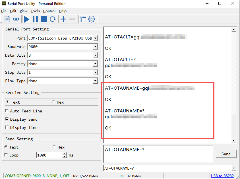
5.3 Configure Username (if required)
AT+OTAUNAME=<username>
Parameters:
- username : Preconfigured Device-Specific Communication Token in MQTT-OTA Server
Take Thingseye as an example: AT+OTAUNAME=<username>
![]()
How to obtain the Client ID: Access Token
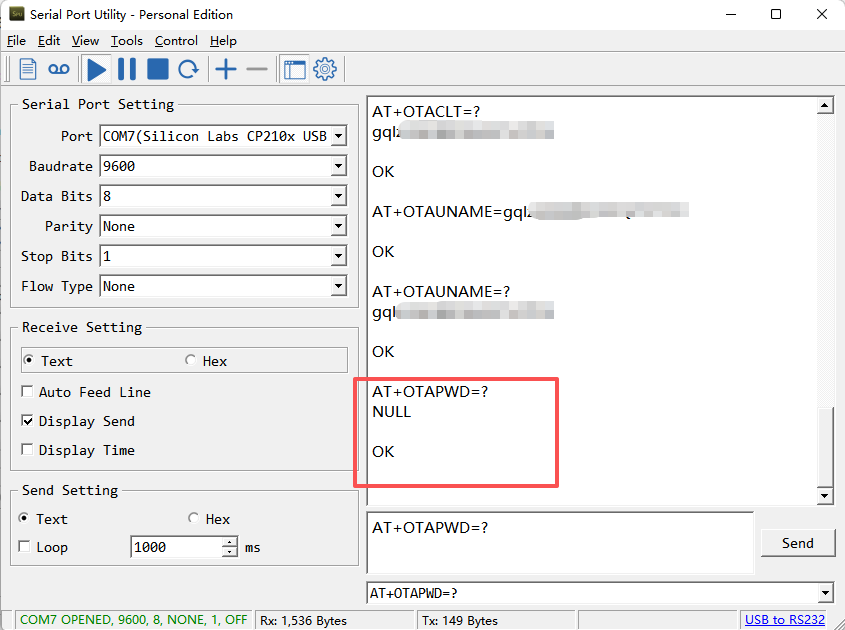
5.4 Configure Password (if required)
AT+OTAPWD=<password>
Parameters:
- password : Based on the configuration entered in the MQTT-OTA server, if the server has not configured a password, the device can default to NULL.
Take Thingseye as an example: AT+OTAPWD=NULL
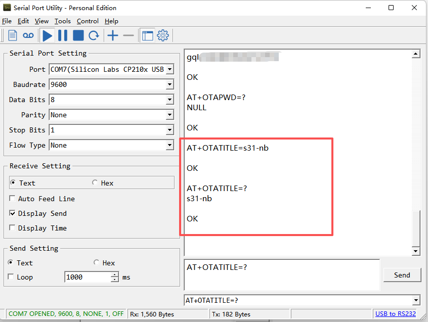
5.5 Configure Firmware Title (Important)
AT+OTATITLE=<firmware\_title>
Example: AT+OTATITLE=s31-nb
Parameters:
- firmware_title: Firmware title used to match server firmware
Default values: s31-nb (for S31-NB devices) or s31-ns (for S31-NS devices)
Warning
Important:
The firmware title returned by the server must exactly match the AT+OTATITLEconfiguration on the device. This comparison is case-sensitive. If the titles do not match, the OTA update will fail with error code 1.
5.6 Configure Firmware Version
AT+OTAVER=<firmware\_version>
Example: AT+OTAVER=v1.5.0
Parameters:
- firmware_version: Current firmware version number
Default value: Current firmware version (e.g., v1.5.0)
Warning
Important:
1. The firmware version returned by the server must be different from the current firmware version configured on the device (or automatically read by the device). Otherwise, the device will consider no update needed (error code 6).
2. By default, no configuration is required for AT+OTAVER The device will automatically read the currently running firmware version and use it for version comparison.
5.7 Save Configuration
All configured parameters are automatically saved to EEPROM and will persist after device reboot.
5.8 One-Step OTA Configuration via JSON Downlink
All OTA configuration parameters (AT+OTASER, AT+OTACLT, AT+OTAUNAME, AT+OTAPWD, AT+OTATITLE, AT+OTAVER) can be configured together using a single JSON downlink command. You can also include AT+UPGRADE in the same command to trigger the OTA update immediately after configuration.
This method simplifies the process by sending all required settings in one go.
For detailed specifications of the JSON downlink format, refer to: Standard JSON Downlink Format
Example JSON Downlink Command
{"Config":"[AT+OTASER=<server\_address>,<port>;AT+OTACLT=<client\_id>``AT+OTAUNAME=<username>;AT+OTAPWD=<password>``AT+OTATITLE=<firmware\_title>;AT+OTAVER=<firmware\_version>;AT+UPGRADE\"} Example with ThingsEye Platform:
To configure a device for ThingsEye OTA and trigger the update, send:
{"Config":"[AT+OTASER=thingseye.io,1885;AT+OTACLT=<your\_access\_token>``AT+OTAUNAME=<your\_access\_token>``AT+OTAPWD=NULL;AT+OTATITLE=s31-nb;AT+OTAVER=v1.50;AT+UPGRADE]"}
Warning
Important Notes:
- This JSON downlink command should be sent through your data server (the server where the device normally sends sensor data), not the OTA server.
- Replace <server_address>,
, <client_id>, , , <firmware_title>, <firmware_version> with your actual values. - The
AT+UPGRADEcommand must be placed at the end of the sequence to ensure all configurations are applied before the OTA process starts.
6. Triggering OTA Update
There are two methods to trigger an OTA firmware update:
6.1 Method 1: Remote Trigger via Downlink Command
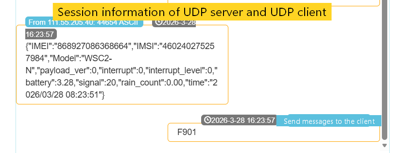
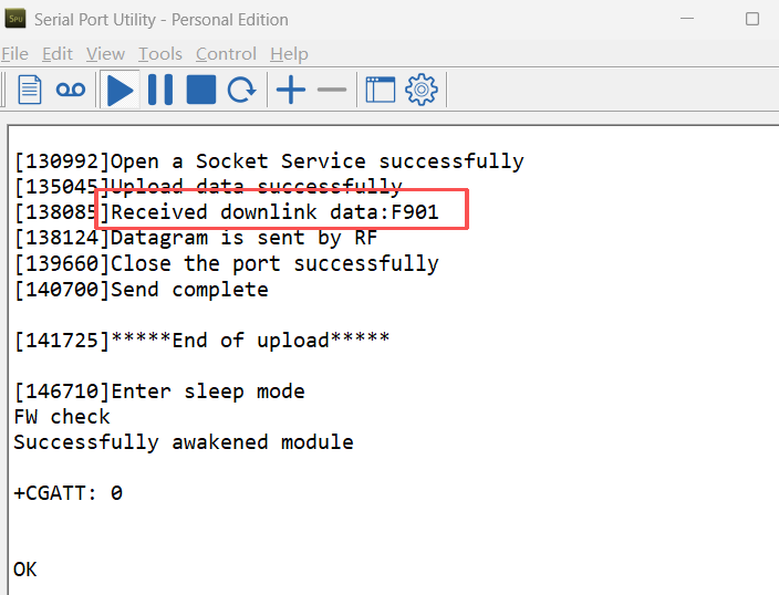
Send a specific downlink command to the device:
Command byte: 0xF9 Parameter: 0x01
Example downlink packet (hexadecimal): F901
When the device receives this command, it will automatically set ota_upgrade_flag=1 and start the OTA update process when the NB module is idle.
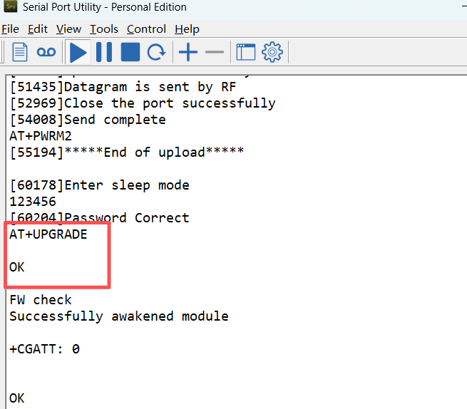
6.2 Method 2: Local Trigger via AT Command
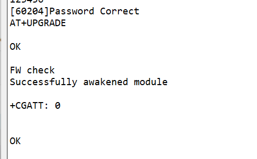
Send the following AT command through the serial interface: AT+UPGRADE
The device will immediately start the OTA update process (if the module is idle).
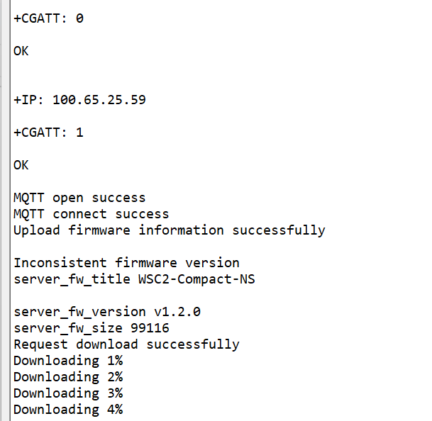
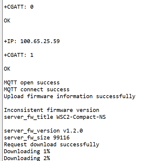
7. OTA Update Process Flow
① Trigger Update: Device receives downlink command 0xF9 or AT+UPGRADEcommand
② Hardware Check: Device verifies external SPI Flash functionality
③ Wake NB Module: Wake up NB-IoT module and establish network connection
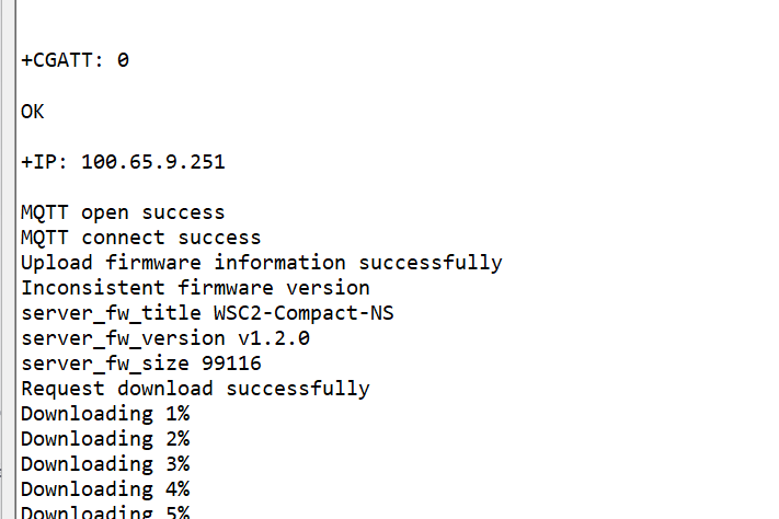
④ Connect to OTA Server: Connect to configured OTA server via MQTT
⑤ Version Verification:
- Device reports current firmware title (
AT+OTATITLEconfiguration) and version (AT+OTAVERconfiguration) - Server returns new firmware information (title, version, size, CRC32)
- Title matching check: Server firmware title must exactly match
AT+OTATITLEconfiguration, otherwise "firmware title mismatch" error (error code 1) - Version check: Server firmware version must differ from
AT+OTAVERconfiguration, otherwise no update needed (error code 6) - Update proceeds only when title matches and version differs
⑥ Storage Preparation: Erase required sectors in external SPI Flash
⑦ Chunk Download:
- Firmware downloaded in 1028-byte chunks (1024 bytes data + 4 bytes CRC32)
- Chunk index starts from 0 and increments sequentially
- Each chunk undergoes CRC32 verification, with up to 3 retries on failure
⑧ Flash Writing: After verification, data is written to external Flash
⑨ Download Completion: Completion flag is cleared after all chunks are successfully downloaded
⑩ Firmware Activation: After device reboot, the bootloader copies the new firmware from external Flash to internal Flash and executes it
8. Error Handling
During the OTA update process, if an error occurs, the device will report the error through its normal data uplink channel (MQTT/CoAP/UDP/TCP) to the server where the device sends its sensor data. This is NOT the OTA server — it is the server you have configured for receiving device data (e.g., ThingsEye, your own MQTT server).
8.1 Error Codes
OTA update process may encounter the following error codes:
Error Code
Description
Recommended Action
1
Firmware title mismatch
Verify server firmware title matches AT+OTATITLEconfiguration
2
Hardware not supported
Check external SPI Flash connection and functionality
3
Command format error
Verify downlink command format is correct
4
OTA server connection timeout
Check network connectivity and server reachability
5
Firmware title not found
Server did not return valid firmware title information
6
Firmware version match
Server firmware version is same as current, no update needed
7
Firmware checksum error
Downloaded chunk CRC32 verification failed (possible network error)
100
OTA update successful
Firmware download completed, waiting for device reboot
The device will retry failed updates up to 3 times. If all retries fail, the device will continue using the original firmware.
8.2 Where to View Error Information
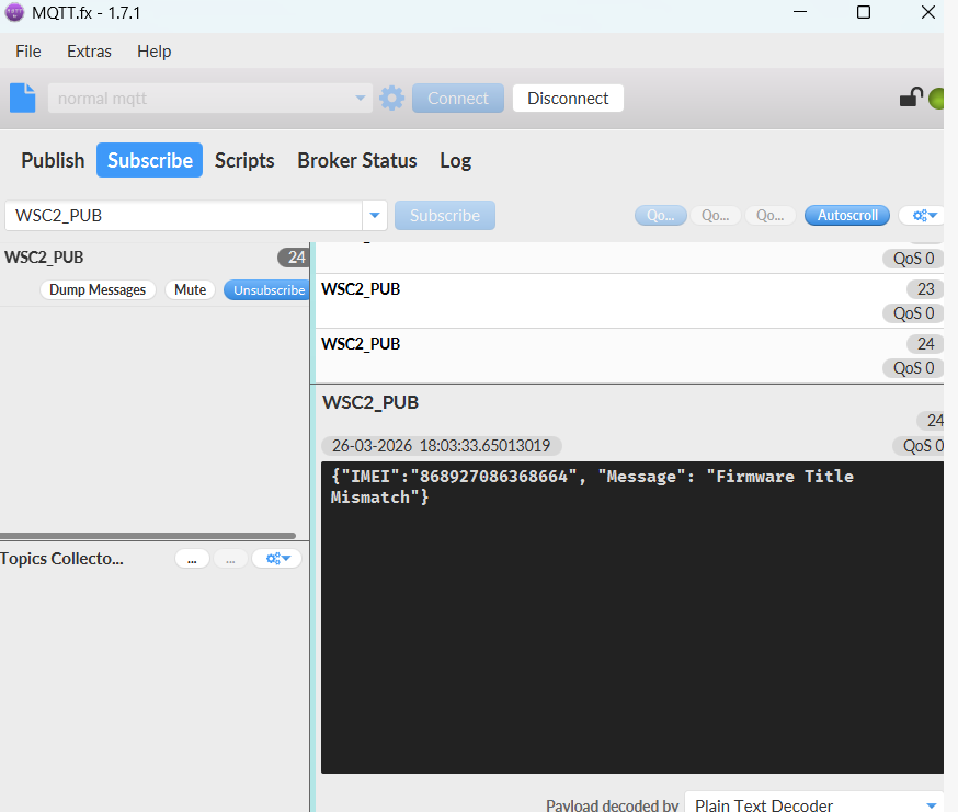
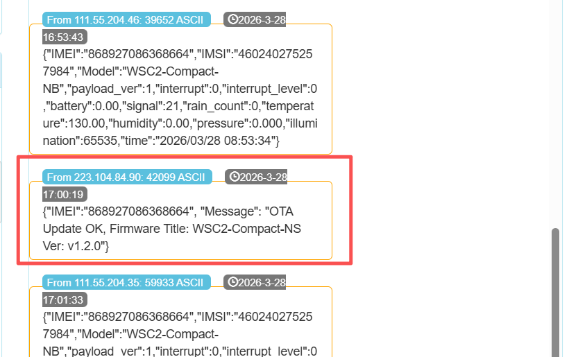
When an error occurs, the device sends a JSON message to your data server (the same server where the device normally reports sensor data). The message format is:
{"IMEI":"<device_imei>", "Message": "<error_description>"}
Example of error message received on the data server (Use MQTT.fx):
8.3 Checking OTA Status
You can monitor the OTA process through the following methods:
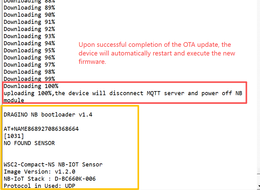
8.3.1 Serial Debug Logs
The device prints detailed status messages during the OTA process.
8.3.2 OTA Completion Notification via Data Server
When the OTA update is successfully completed, the device will send a confirmation message to your data server (the same server where the device normally reports sensor data). The message format is:
{"IMEI":"<device_imei>", "Message": "OTA Update OK, Firmware Title:
Example:
Warning
Important Limitations:
-
The OTA completion notification is only sent when upgrading between the same model firmware (e.g., WSC2-Compact-NS v1.1.0 → WSC2-Compact-NS v1.2.0).
-
If you upgrade between different firmware models (e.g., WSC2-Compact-NS → S31-NB), the device will reboot with the new firmware. Since different model firmware have different configuration structures, user settings (server addresses, AT configurations, etc.) will be cleared. As a result, the device may lose connection to the data server and will not be able to send the completion notification.
9. Important Considerations
Power Stability: Ensure stable power supply during OTA update to prevent interruption
Network Signal: Maintain good NB-IoT network signal strength throughout the process
Storage Space: External SPI Flash must have sufficient available space (minimum 128KB)
Version Compatibility: Ensure server firmware title is compatible with the device model
Security: Current OTA implementation uses CRC32 verification only. For high-security environments, additional digital signature verification is recommended
10. Debugging and Logs
If OTA update fails, check debug information through the serial interface:
- Baud rate: 9600
- Data bits: 8
- Stop bits: 1
- Parity: None
Monitor the device output logs to understand update progress and error causes.
0
Toggle the left panel column.