General Configure for -CB & -CS models (NB-IoT, LTE-M)
1. The use of this guideline
This configure instruction is for Dragino NB-IoT models with -CB or -CS suffix, for example DDS75-CB. These models use the same NB-IoT Module BG95-M2 and has the same software structure. The have the same configure instruction to different IoT servers. Use can follow the instruction here to see how to configure to connect to those servers.
2. Attach Network
2.1 General Configure to attach network
To attache end nodes to NB-IoT or LTE-M Network, You need to:
- Get a NB-IoT or LTE-M SIM card from Service Provider. (Not the same as the SIM card we use in mobile phone)
- Power Off End Node ( See below for the power off/on position)
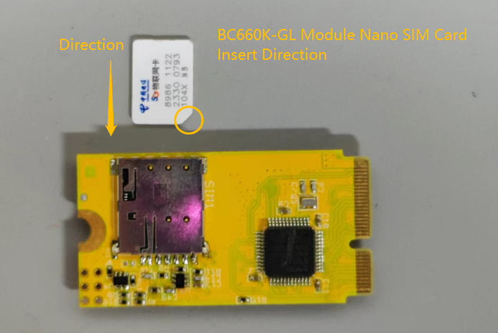
- Insert the SIM card to Sensor. ( See below for direction)
- Power On End Node
- Configure APN in the sensor (
AT+APN=<APN>, exampleAT+APN=iot.1nce.net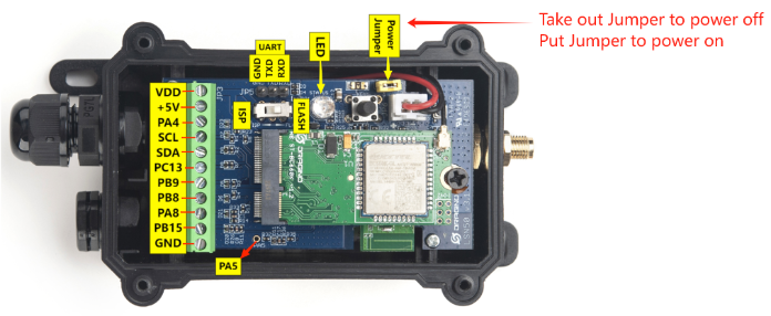
After doing above, the end nodes should be able to attach to NB-IoT network .
The -CB and -CS models support LTE Cat NB2 and LTE-M (CAT-M1), with below frequency band: multiple frequency bands of
-- CAT-NB2: B1/B2/B3/B4/B5/B8/B12/B13/B18/B19/B20/B25/B28/B66/B71/B85 .
-- CAT-M1: B1/B2/B3/B4/B5/B8/B12/B13/B18/B19/B20/B25/B26/B27/B28/B66/B85 .
Make sure you use a the NB-IoT or LTE-M SIM card.
SIM Provider
AT+APN=
NB-IoT Coverage LTE-M Coverage Comments 1NCE
iot.1nce.net
Austria, Belgium, Bulgaria, China, Croatia, Czech Republic, Denmark, Estonia, Finland, Germany, Great Britain, Greece, Hungary, Ireland,Italy, Latvia, Malta, Netherlands, Norway, Portugal, Puerto Rico, Russia, Slovak,Republic, Slovenia, Spain, Sweden, Switzerland, Taiwan, USA, US Virgin Islands
Argentina, Austria, Australia, Belgium, Canada, Denmark,Estonia, Finland, France, Germany, Great Britain, Hungary, Ireland, Japan,Jersey, Korea, Repiblic of, Latvia, Luxembourg, Mexico, Netherlands, New Zealand, Norway, Poland, Puerto Rico, Romania, Spain, Sweden, Switzerland,Taiwan, USA, US Virgin Islands.
UK: Band20
China Mobile
No need configure
China Mainland, HongKong
China Telecom
ctnb
China Mainland
2.2 Speed Up Network Attach time
BG95-M2 supports multi bands in NB-IoT and LTE-M. It will search one by one and try to attach, this will take a lot of time and even cause attach fail and show Signal Strenght:99.
**Note:**Before using the NB module command, users need to power on the NB module. Run the AT+QSWcommand to turn on and off the NB module.Remember to shut down after using the NB module command, otherwise it will consume power.
Attache to 1NCE card for Australia use:
AT+COPS=1,2,"50501",8AT+QCFG="band",0,0x8000000,0x8000000,1After connection is successful, user can useAT+QENG="servingcell"to check which band is actually in used.
AT+QENG="servingcell"
+QENG: "servingcell","NOCONN","eMTC","FD
D",505,01,90D2C0B,258,9410,28,5,5,901A,-112,-17,-80,10,27
See bands used for different provider: NB-IoT Deployment , Bands, Operator list
1. Configure Frequency Band
AT+QCFG="band"\[,<GSM\_bandval>,<eMTC\_bandval>,<NB-IoT\_bandval>\[
<GSM_bandval>:
0 No change
0x1 EGSM900
0x2 DCS1800
0x4 GSM850
0x8 PCS1900
0xF All of the supported bands above
<eMTC_bandval>:
0 No change
0x1 LTE B1
0x2 LTE B2
0x4 LTE B3
0x8 LTE B4
0x10 LTE B5
0x80 LTE B8
0x800 LTE B12
0x1000 LTE B13
0x20000 LTE B18
0x40000 LTE B19
0x80000 LTE B20
0x1000000 LTE B25
0x2000000 LTE B26
0x4000000 LTE B27
0x8000000 LTE B28
0x40000000 LTE B31
0x20000000000000000 LTE B66
0x800000000000000000 LTE B72
0x1000000000000000000 LTE B73
0x1000000000000000000000 LTE B85
<NB-IoT_bandval>:
0 No change
0x1 LTE B1
0x2 LTE B2
0x4 LTE B3
0x8 LTE B4
0x10 LTE B5
0x80 LTE B8
0x800 LTE B12
0x1000 LTE B13
0x20000 LTE B18
0x40000 LTE B19
0x80000 LTE B20
0x1000000 LTE B25
0x8000000 LTE B28
0x40000000 LTE B31
0x20000000000000000 LTE B66
0x400000000000000000 LTE B71
0x800000000000000000 LTE B72
0x1000000000000000000 LTE B73
0x1000000000000000000000 LTE B85
For example, setting the LTE-M network frequency band to 3.
AT+QCFG="band",0xF,0x4,0,1
When searching for all bands, the value of this command is set to:
AT+QCFG="band",0xF,0x100002000000000f0e189f,0x10004200000000090e189f1
2. Configure search network sequence
AT+QCFG="nwscanseq",<scanseq>,1
00 Automatic (eMTC → NB-IoT → GSM)
01 GSM
02 eMTC
03 NB-IoT
AT+QCFG="nwscanseq",02,1 //Priority search for eMTC
3. Configure Network Category to be Searched for under LTE RAT
AT+QCFG="iotopmode",mode,1
0 eMTC
1 NB-IoT
2 eMTC and NB-IoT
4. AT command to set frequency band and network category
AT+QBAND=0x100002000000000f0e189f,0x10004200000000090e189f //<eMTC_bandval>,<NB-IoT_bandval>
AT+IOTMOD=0 // 0 eMTC 1 NB-IoT 2 eMTC and NB-IoT
Example :
Taking the use of 1nce cards in the United States as an example.
AT+APN=iot.1nce.net //set APN
AT+QBAND=0x100180A,0 // eMTC :Set frequency band B2,B4,B12,B13,B25 NB-IoT:No change
AT+IOTMOD=0 // Set eMTC Network
Setting the above commands in the United States will greatly reduce the network search time of the NB module.
3. Configure to connect to different servers
3.1 General UDP Connection
The NB-IoT Sensor can send packet to server use UDP protocol.
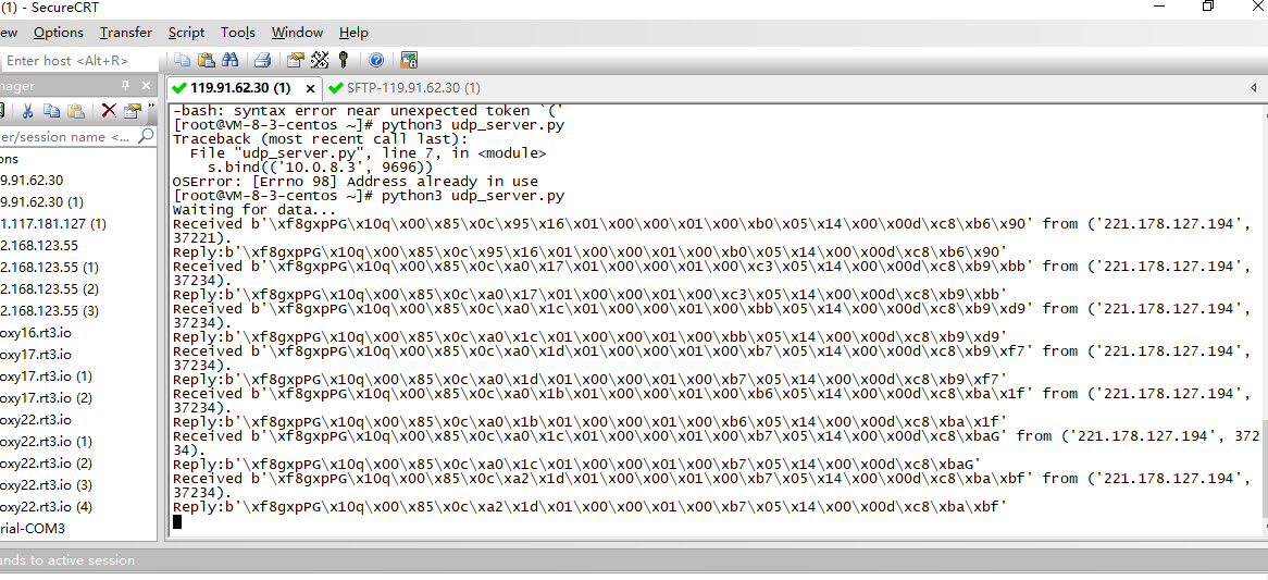
3.1.1 Simulate UDP Connection by PC tool
We can use PC tool to simulate UDP connection to make sure server works ok.
3.1.2 Configure NB-IoT Sensor
3.1.2.1 AT Commands
AT Commands:
-
AT+PRO=2,0// Set to use UDP protocol to uplink ,Payload Type select Hex payload -
AT+SERVADDR=8.217.91.207,1999// Set UDP server address and port
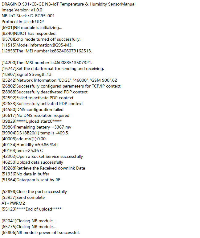
3.1.2.2 Uplink Example
3.2 General COAP Connection
The NB-IoT Sensor can send packet to server use COAP protocol.
Below are the commands.
AT Commands:
-
AT+PRO=1,0// Set to use COAP protocol to uplink, Payload Type select Hex payload. -
AT+SERVADDR=120.24.4.116,5683// Set COAP server address and port -
AT+URI1=11,"i"// Configure CoAP Message Options -
AT+URI2=11,"aaa05e26-4d6d-f01b-660e-1d8de4a3bfe1"// Configure CoAP Message Options
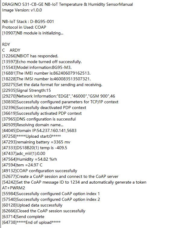
3.2.1 Uplink Example
3.2 General MQTT Connection
The NB-IoT Sensor can send packet to server use MQTT protocol.
Below are the commands.
AT Commands:
-
AT+PRO=3,0// Set to use MQTT protocol to uplink, Payload Type select Hex payload. -
AT+SERVADDR=120.24.4.116,1883// Set MQTT server address and port -
AT+CLIENT=CLIENT// Set up the CLIENT of MQTT -
AT+UNAME=UNAME// Set the username of MQTT -
AT+PWD=PWD// Set the password of MQTT -
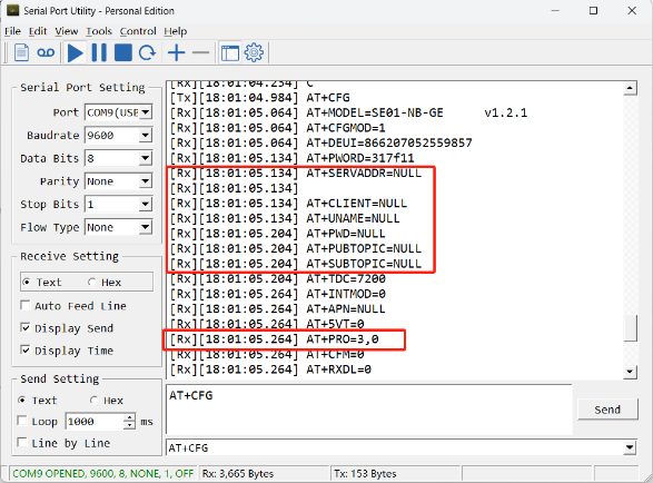
AT+PUBTOPIC=NSE01\_PUB// Set the sending topic of MQTT -
AT+SUBTOPIC=NSE01\_SUB// Set the subscription topic of MQTT
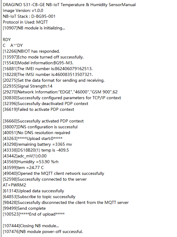
Notice: MQTT protocol has a much higher power consumption compare with UDP/CoAP protocol. Please check the power analyze document and adjust the uplink period to a suitable interval.
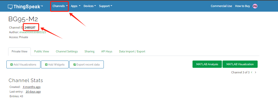
3.3 ThingSpeak (via MQTT)
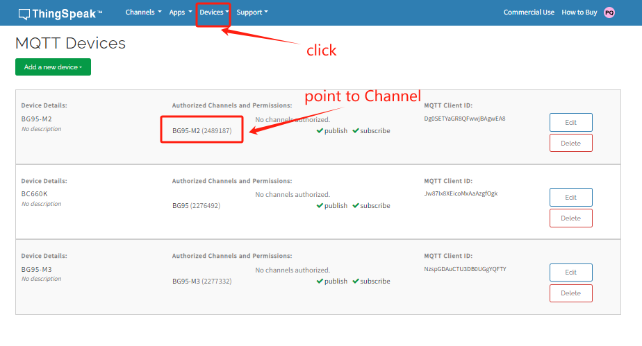
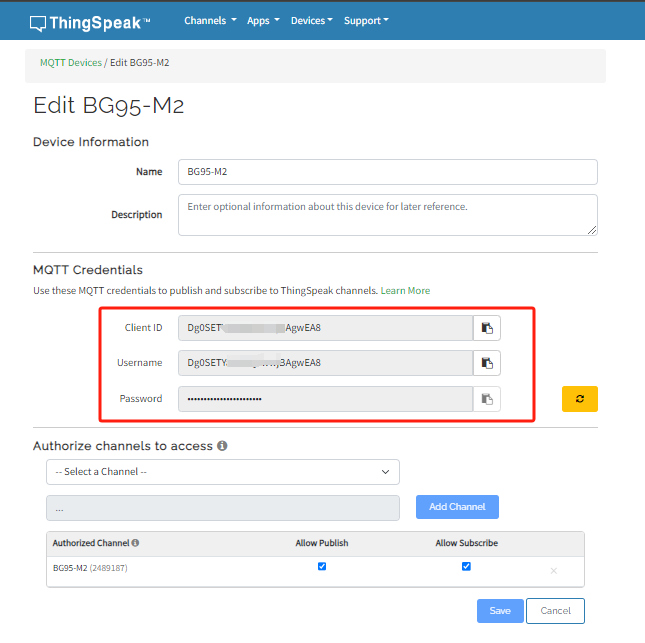
3.3.1 Get MQTT Credentials
ThingSpeak connection uses MQTT Connection. So we need to get MQTT Credentials first. You need to point MQTT Devices to ThingSpeak Channel as well.
3.3.2 Simulate with MQTT.fx
3.3.2.1 Establish MQTT Connection
After we got MQTT Credentials, we can first simulate with PC tool MQTT.fx tool to see if the Credentials and settings are fine.
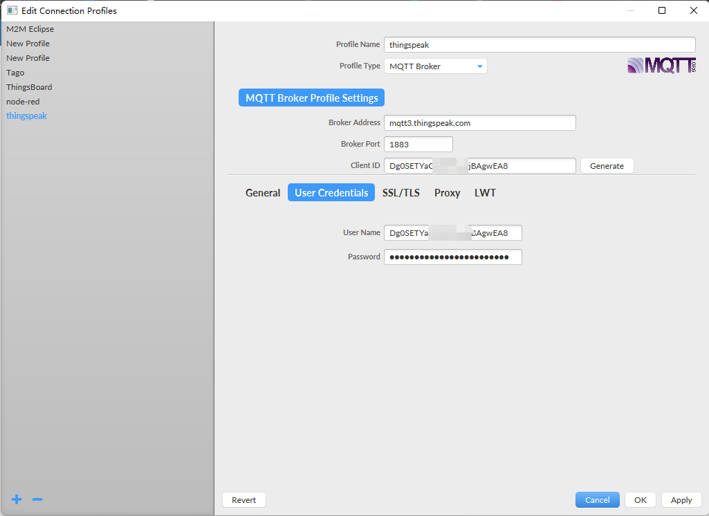
-
Broker Address: mqtt3.thingspeak.com
-
Broker Port: 1883
-
Client ID:
-
User Name:
-
Password:
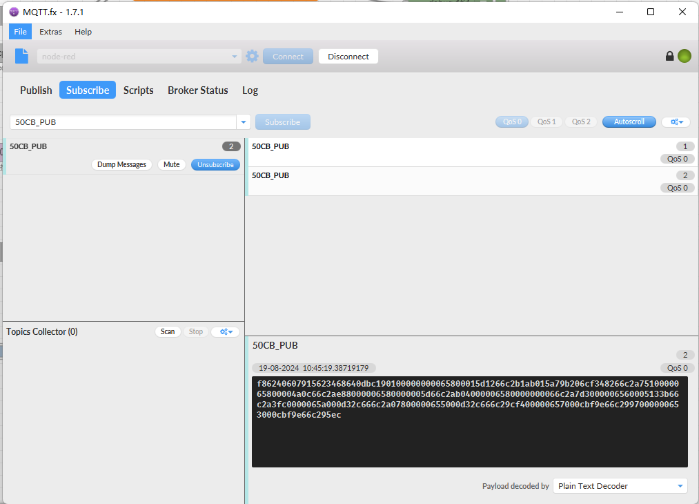
3.3.2.2 Publish Data to ThingSpeak Channel
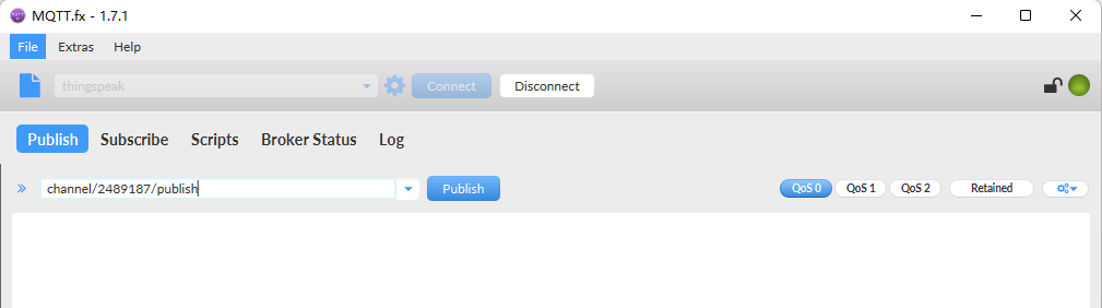
In MQTT.fx, we can publish below info:
-
Topic: channels/YOUR_CHANNEL_ID/publish
-
Payload: field1=63&field2=67&status=MQTTPUBLISH
Where 63 and 67 are the value to be published to field1 & field2.
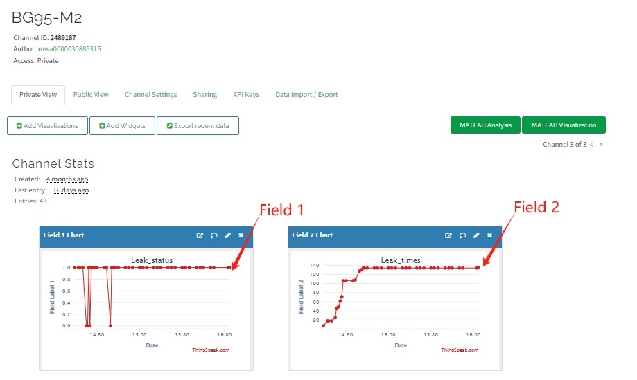
Result:
3.3.3 Configure NB-IoT Sensor for connection
3.3.3.1 AT Commands:
In the NB-IoT, we can run below commands so to publish the channels like MQTT.fx
-
AT+PRO=3,1// Set to use ThingSpeak Server and Related Payload -
AT+CLIENT=<Your ThingSpeak MQTT ClientID> -
AT+UNAME=<Your ThingSpeak MQTT User Name> -
AT+PWD=<Your ThingSpeak MQTT Password> -
AT+PUBTOPIC=<YOUR\_CHANNEL\_ID> -
AT+SUBTOPIC=<YOUR\_CHANNEL\_ID>
3.3.3.2 Uplink Examples
For SE01-NB
For DDS20-NB
For DDS45-NB
For DDS75-NB
For NMDS120-NB
For SPH01-NB
For NLM01-NB
For NMDS200-NB
For CPN01-NB
For DS03A-NB
For SN50V3-NB
3.3.3.3 Map fields to sensor value
When NB-IoT sensor upload to ThingSpeak. The payload already specify which fileds related to which sensor value. Use need to create fileds in Channels Settings. with name so to see the value correctly.
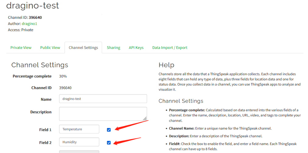
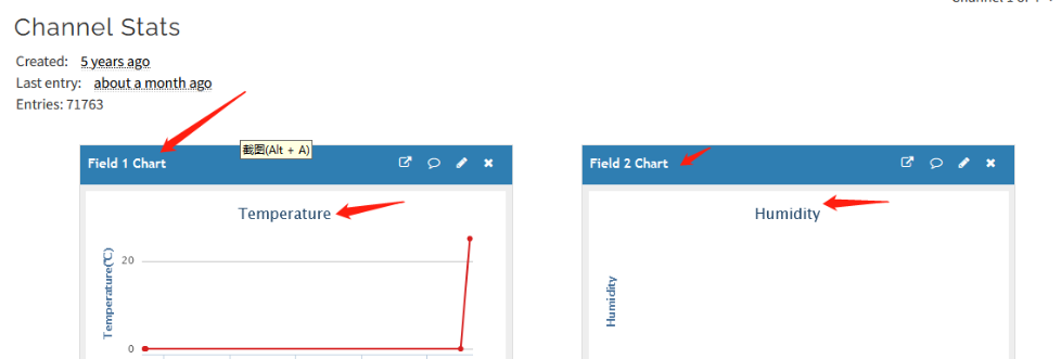
Below is the NB-IoT Product Table show the mapping.
Field1
Field2
Field3
Field4
Field5
Field6
Field7
Field8
Field9
Field10
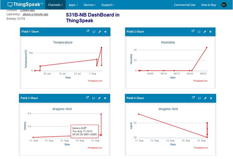
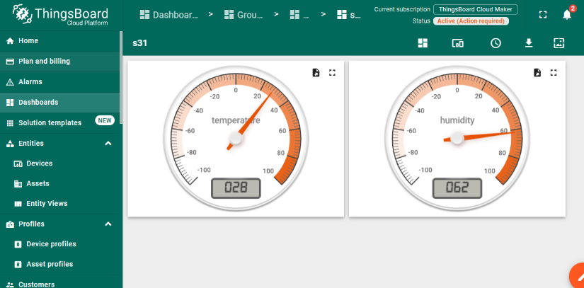
S31x-NB
Temperature
Humidity
Battery
RSSI
SE01-NB
Temperature
Humidity
conduct
dielectric_constant
Battery
RSSI
DDS20-NB
distance
Battery
RSSI
DDS45-NB
distance
Battery
RSSI
DDS75-NB
distance
Battery
RSSI
NMDS120-NB
distance
Battery
RSSI
SPH01-NB
ph
Temperature
Battery
RSSI
NLM01-NB
Humidity
Temperature
Battery
RSSI
NMDS200-NB
distance1
distance2
Battery
RSSI
CPN01-NB
alarm
count
door open duration
calc flag
Battery
RSSI
DS03A-NB
level
alarm
pb14door open num
pb14 last open time
pb15 level status
pb15 alarm status
pb15 door open num
pb15 last open time
Battery
RSSI
SN50V3-NB mod1
mod
Battery
RSSI
DS18B20 Temp
exit_state/input PA4
adc0
Temperature
Humidity
SN50V3-NB mod2
mod
Battery
RSSI
DS18B20 Temp
exit_state/input PA4
adc0
distance
SN50V3-NB mod3
mod
Battery
RSSI
adc0
exit_state/input PA4
adc1
Temperature
Humidity
adc4
SN50V3-NB mod4
mod
Battery
RSSI
DS18B20 Temp
adc0
exit_state/input PA4
DS18B20 Temp2
DS18B20 Temp3
SN50V3-NB mod5
mod
Battery
RSSI
DS18B20 Temp
adc0
exit_state/input PA4
Weight
SN50V3-NB mod6
mod
Battery
RSSI
count
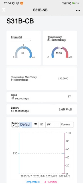
3.4 Datacake
Dragino NB-IoT sensors has its template in Datacake Platform. There are two version for NB Sensor,
As example for S31B-CB. there are two versions: S31B-CB-1D and S31B-CB-GE.
-
S31B-CB-1D: This version have pre-configure DataCake connection. User just need to Power on this device, it will auto connect send data to DataCake Server.
-
S31B-CB-GE: This verson doesn't have pre-configure Datacake connection. User need to enter the AT Commands to connect to Datacake. See below for instruction.
3.4.1 For device Already has template
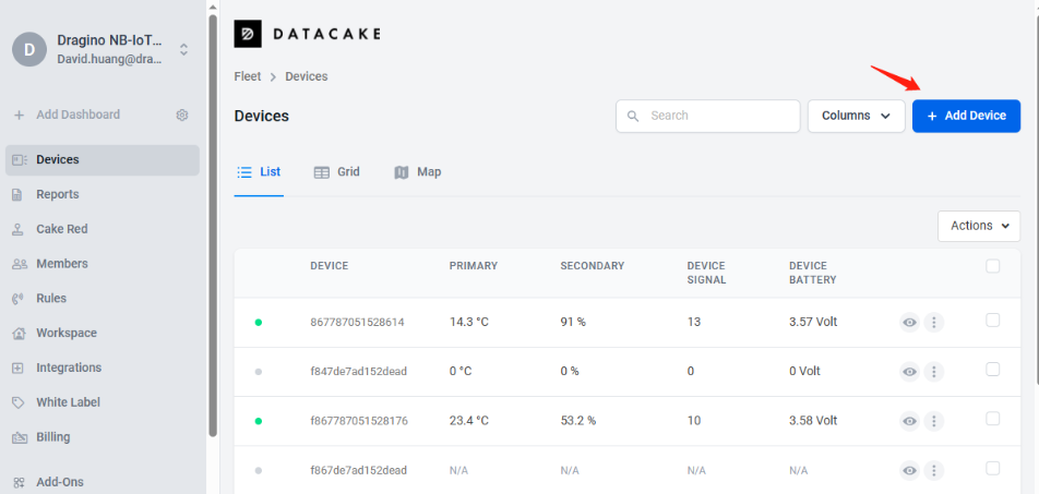
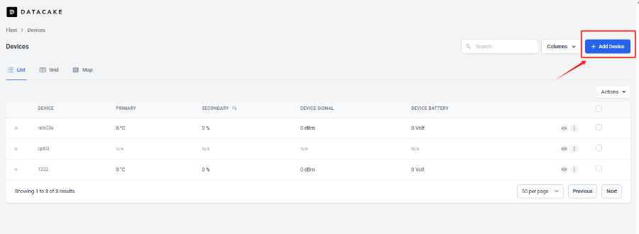
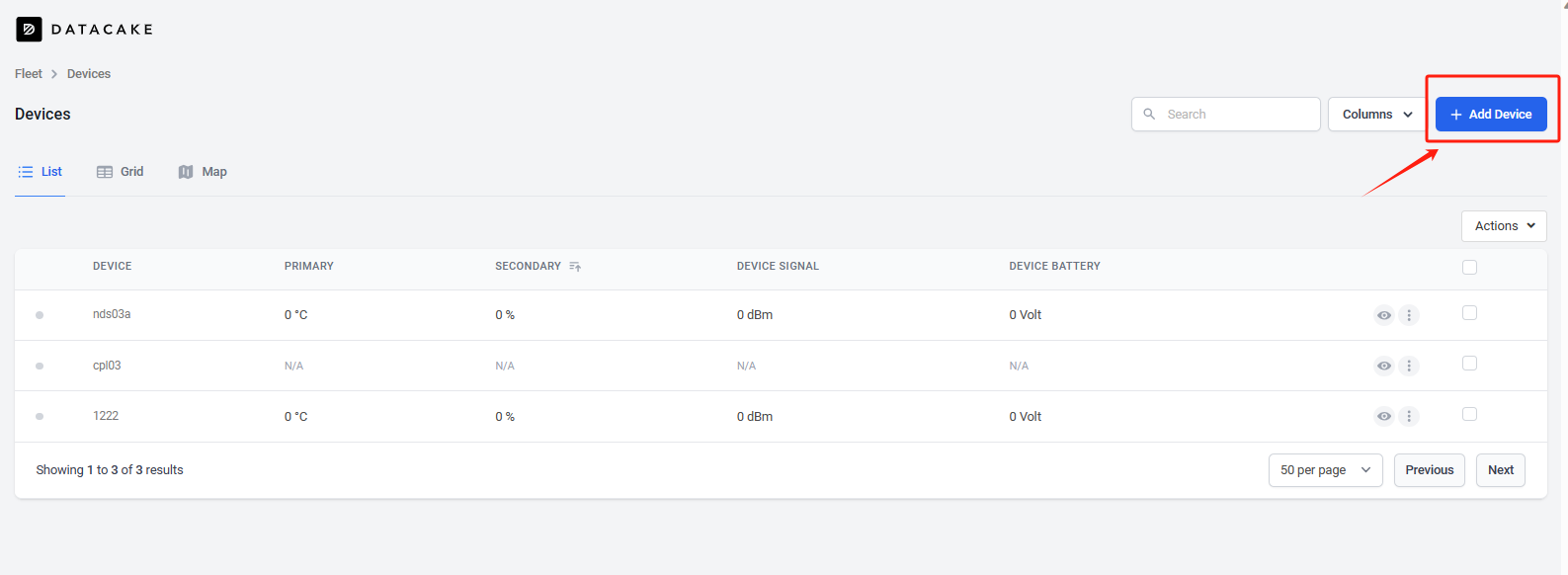
3.4.1.1 Create Device
Add Device in DataCake.
Choose the correct model from template.
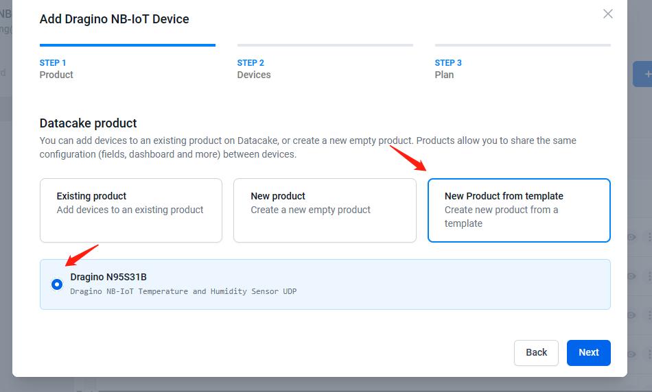
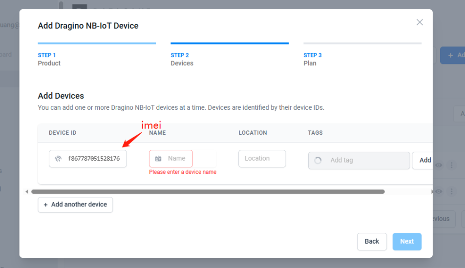
Fill Device ID. The device ID needs to be filled in with IMEI, and a prefix of 'f' needs to be added.
3.4.2 For Device already registered in DataCake before shipped
3.4.2.1 Scan QR Code to get the device info
Users can use their phones or computers to scan QR codes to obtain device data information.

3.4.2.2 Claim Device to User Account
By Default, the device is registered in Dragino's DataCake Account. User can Claim it to his account.
3.4.3 Manual Add Decoder in DataCake ( don't use the template in DataCake)
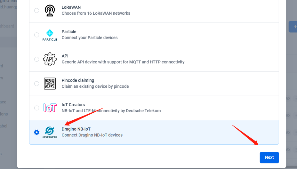
Step1: Add a device
Step2: Choose your device type,please select dragino NB-IOT device
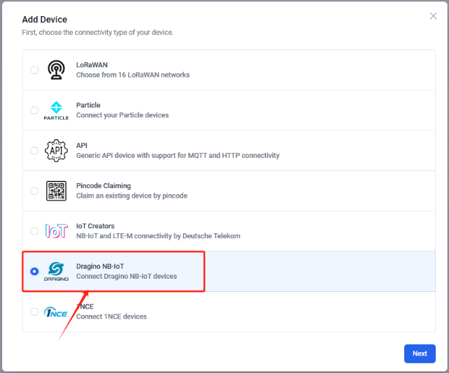
Step3: Choose to create a new device
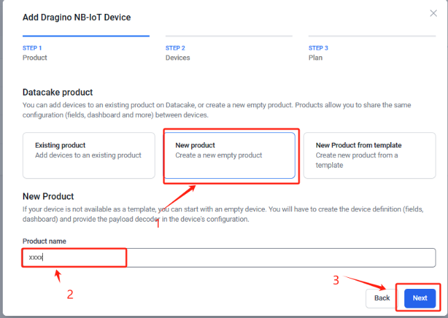
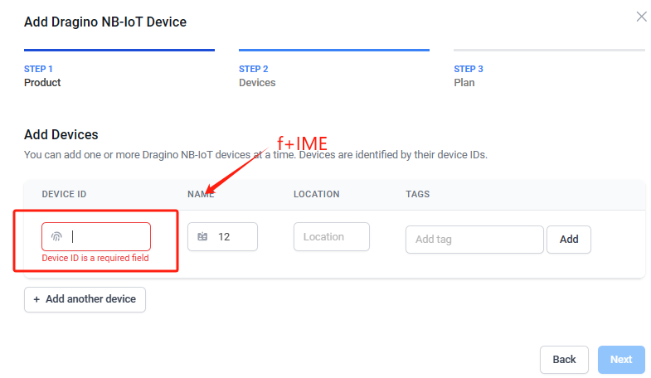
Step4: Fill in the device ID of your NB device
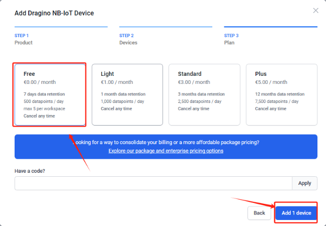
Step5: Please select your device plan according to your needs and complete the creation of the device
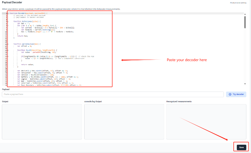
Step6: Please add the decoder at the payload decoder of the device configuration. Decoder location:dragino-end-node-decoder/Datacake-Dragino_NB at main · dragino/dragino-end-node-decoder (github.com)
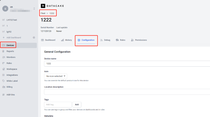
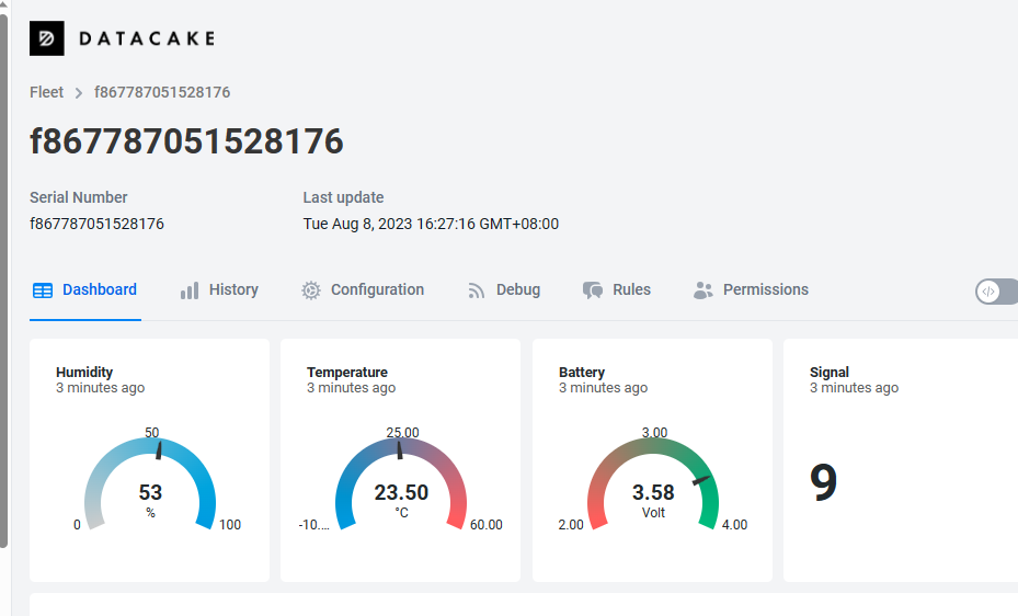
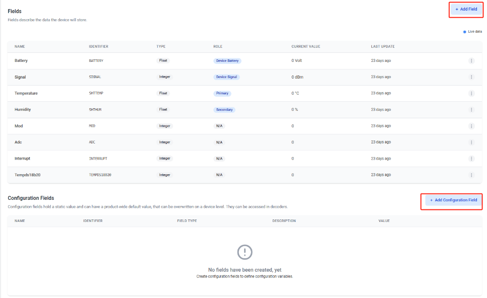
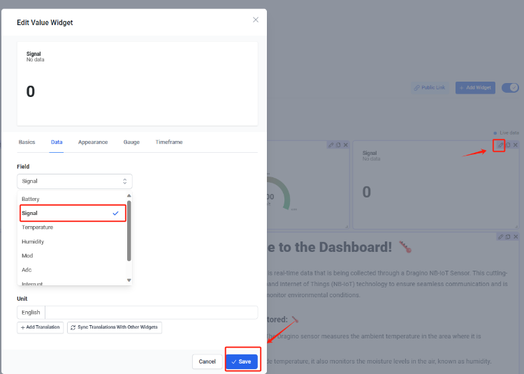
Step7: Add the output of the decoder as a field
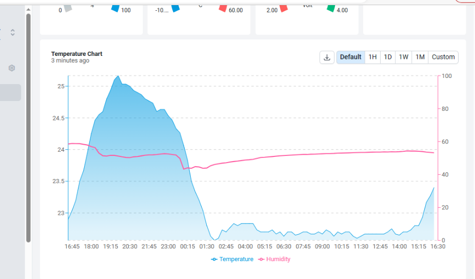
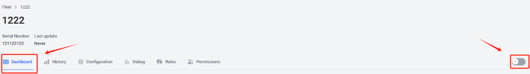
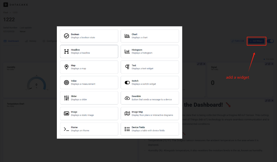
Step8: Customize the dashboard and use fields as parameters of the dashboard
3.4.4 For device have not configured to connect to DataCake
Use AT command for connecting to DataCake
AT+PRO=2,0
AT+SERVADDR=67.207.76.90,4445
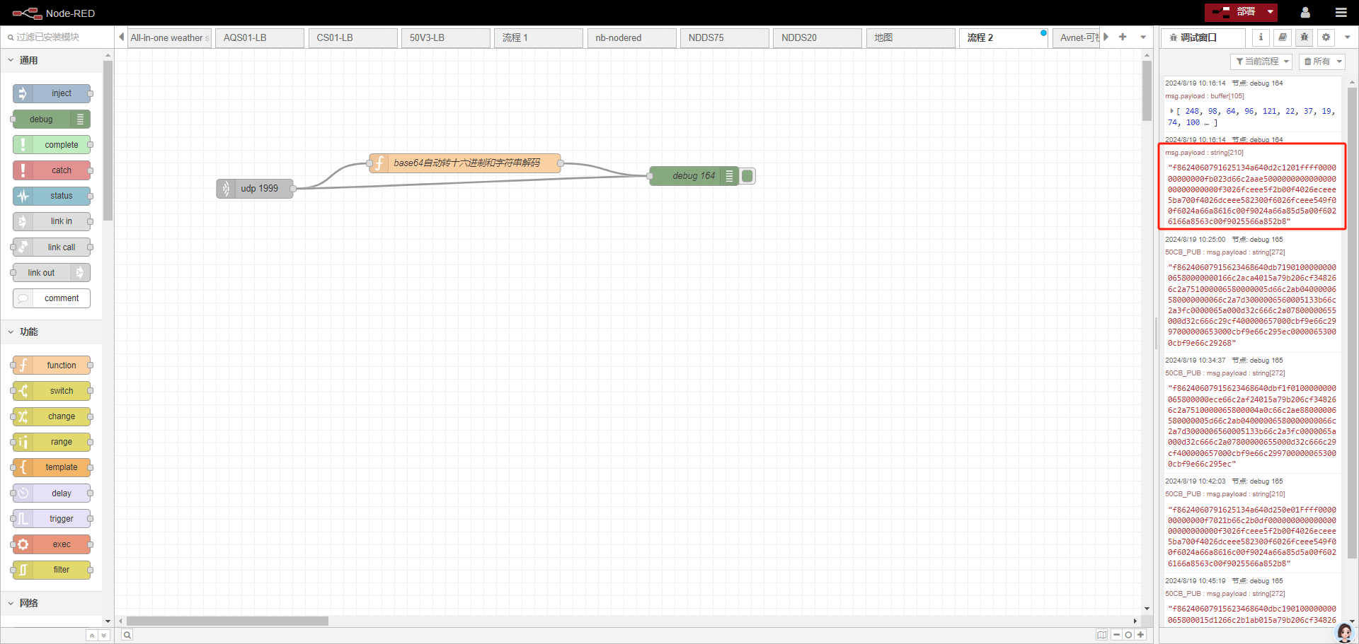
3.5 Node-Red (via MQTT)
3.5.1 Configure Node-Red
Take S31-NB UDP protocol as an example.
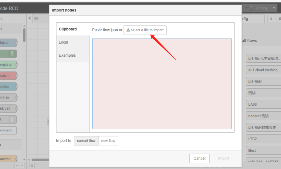
Dragino provides input flow examples for the sensors.
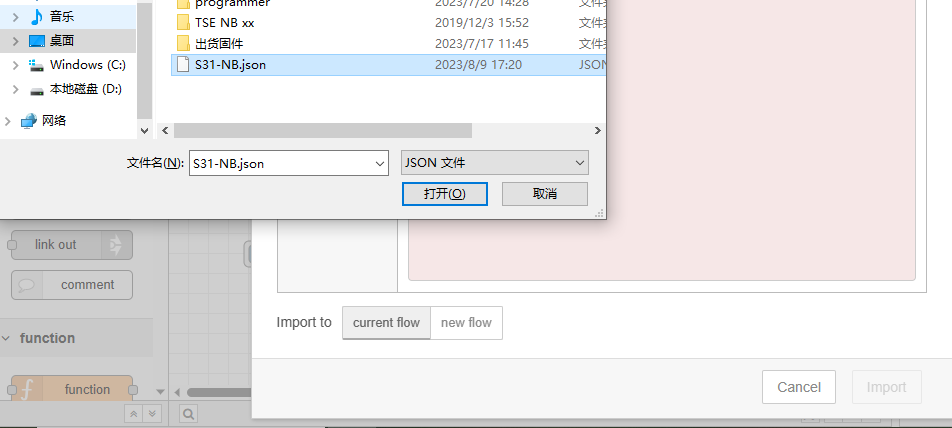
User can download the required JSON file through Dragino Node-RED input flow template.
Download sample JSON file link: https://www.dropbox.com/sh/mduw85jcuwsua22/AAAvwPhg9z6dLjJhmZjqBf_ma?dl=0
We can directly import the template.
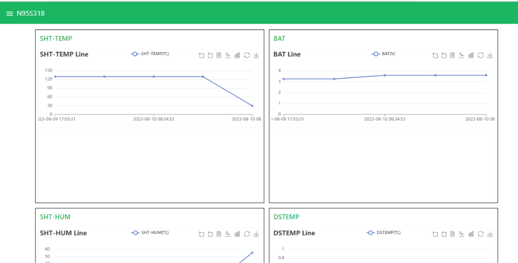
The templates for S31-NB and NB95S31B are the same.
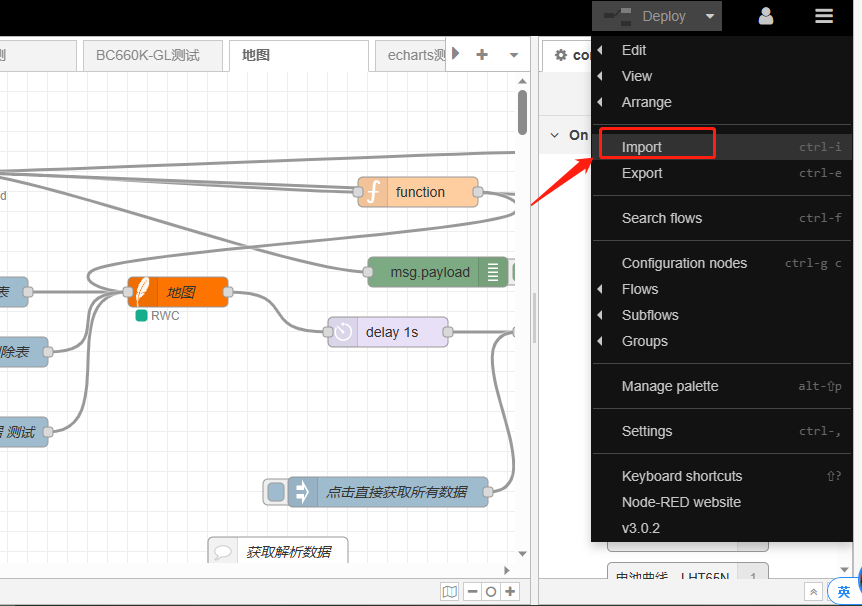
Please select the NB95S31B template.
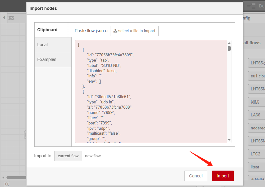
Successfully imported template.
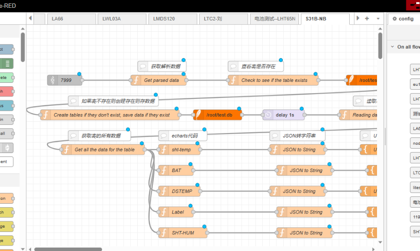
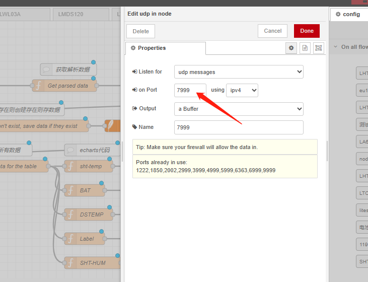
Users can set UDP port.
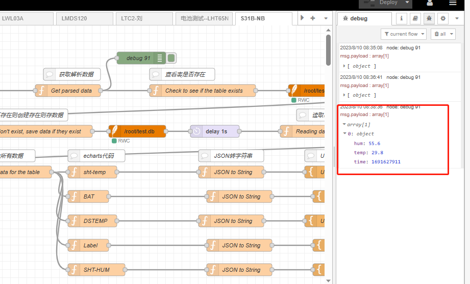
3.5.2 Simulate Connection
We have completed the configuration of UDP. We can try sending packets to node red.
3.5.3 Configure NB-IoT Sensors
AT+PRO=3,0 or 3,5// hex format or json formatAT+SUBTOPIC=<device name>or User Defined-AT+PUBTOPIC=<device name>or User Defined-AT+CLIENT=<device name> or User Defined-AT+UNAME=<device name> or User Defined-AT+PWD=“Your device token”
3.6 ThingsBoard.Cloud (via MQTT)
3.6.1 Configure ThingsBoard
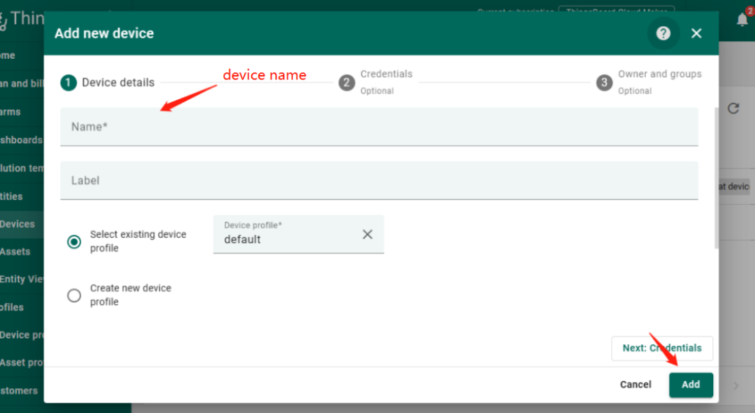
3.6.1.1 Create Device
Create a New Device in ThingsBoard. Record Device Name which is used for MQTT connection.
3.6.1.2 Create Uplink & Downlink Converter
Uplink Converter
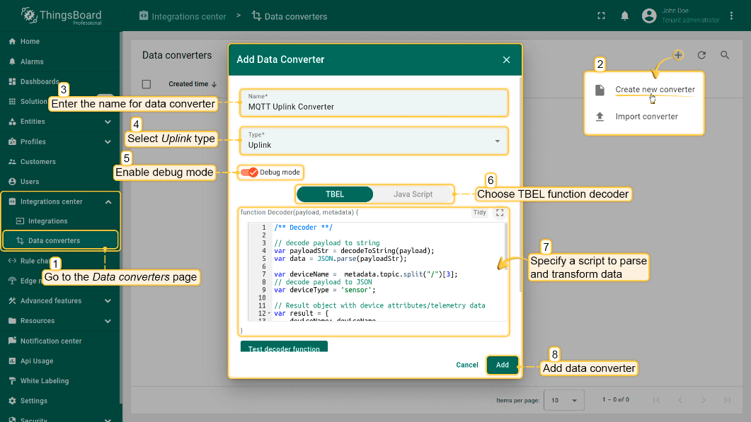
The purpose of the decoder function is to parse the incoming data and metadata to a format that ThingsBoard can consume. deviceName and deviceType are required, while attributes and telemetry are optional. Attributes and telemetry are flat key-value objects. Nested objects are not supported.
To create an uplink converter go to the Integrations center -> Data converters page and click “plus” button. Name it “MQTT Uplink Converter” and select type "Uplink". Use debug mode for now.
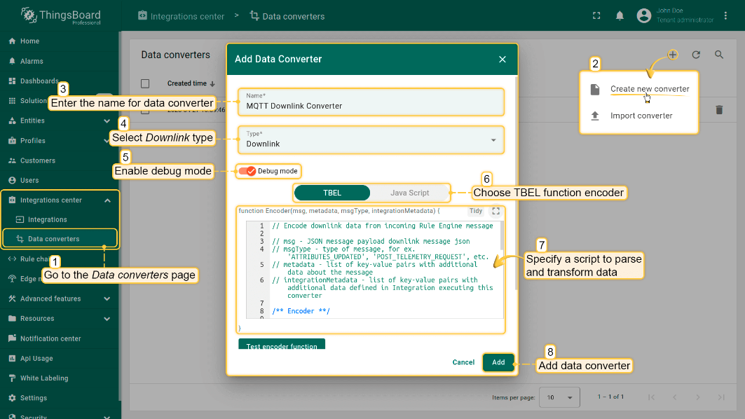
 Downlink Converter
The Downlink converter transforming outgoing RPC message and then the Integration sends it to external MQTT broke
 Note: Our device payload is already human readable data. Therefore, users do not need to write decoders. Simply create by default.
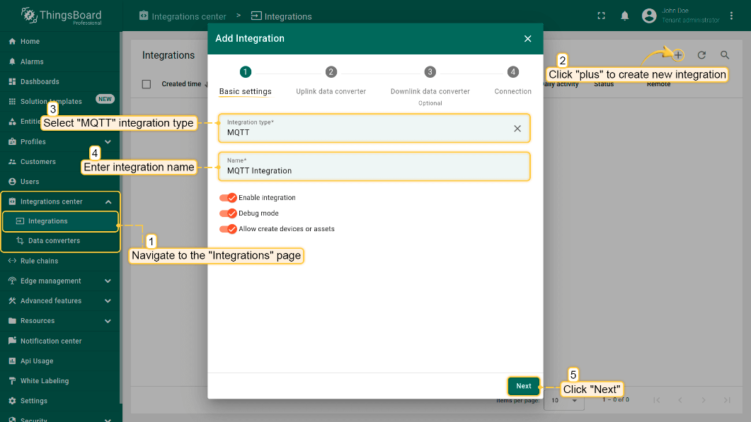
3.6.1.3 MQTT Integration Setup
Go to the Integrations center -> Integrations page and click “plus” icon to add a new integration. Name it “MQTT Integration”, select type MQTT;
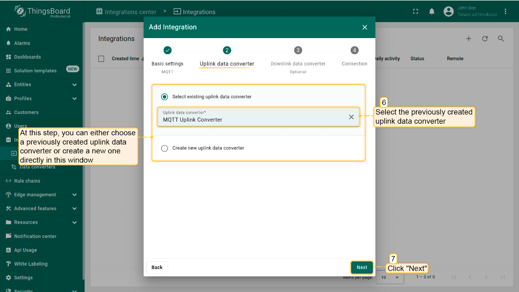
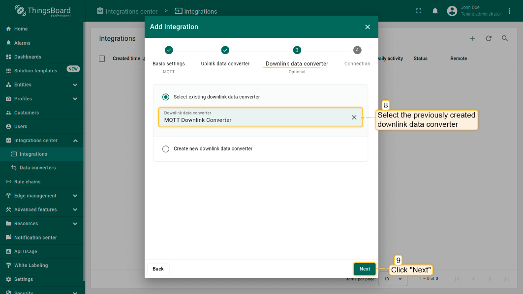
- The next steps is to add the recently created uplink and downlink converters;
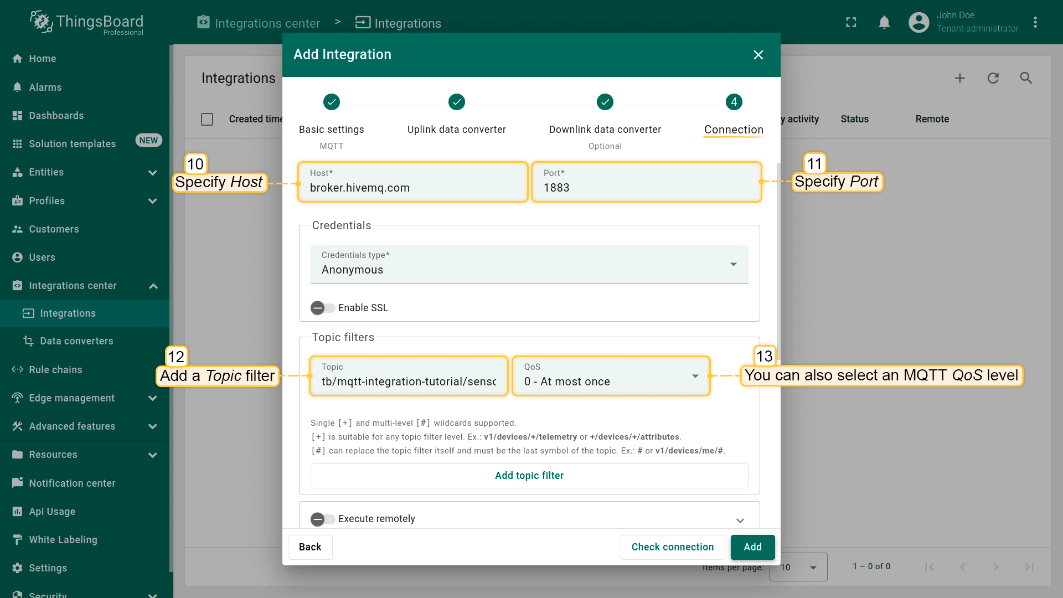
Add a topic filter:
Consistent with the theme of the node setting.
You can also select an MQTT QoS level. We use MQTT QoS level 0 (At most once) by default;
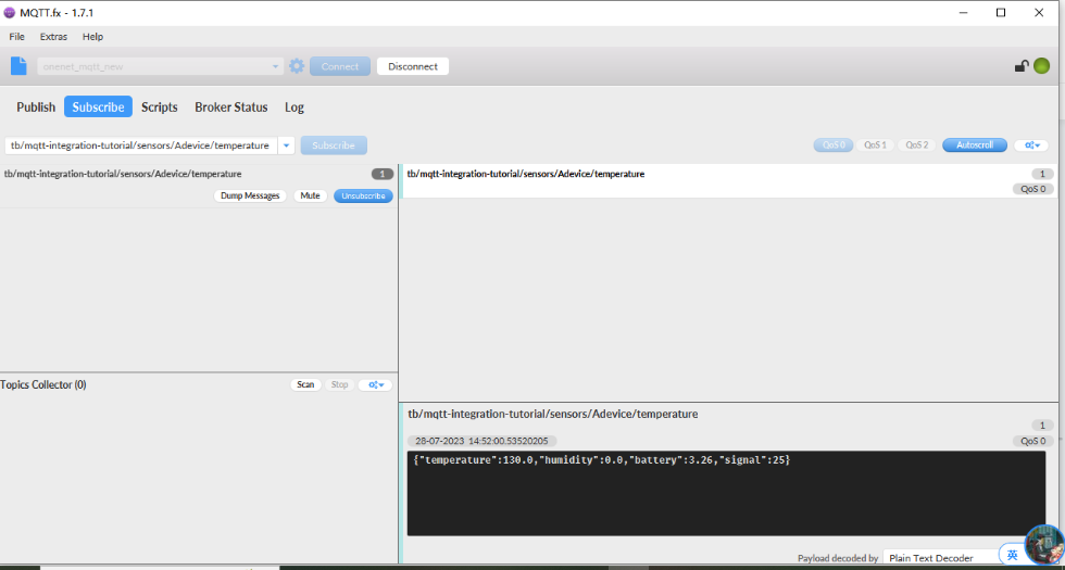
3.6.2 Simulate with MQTT.fx
3.6.3 Configure NB-IoT Sensor
AT Commands
-
AT+PRO=3,3// Use MQTT to connect to ThingsBoard. Payload Type set to 3. -
AT+SUBTOPIC=<device name> -
AT+PUBTOPIC=<device name> -
AT+CLIENT=<device name> or User Defined -
AT+UNAME=<device name> or User Defined -
AT+PWD=<device name> or User DefinedTest Uplink by click the button for 1 second
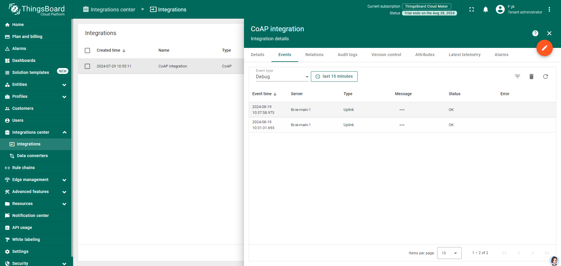
3.7 ThingsBoard.Cloud (via COAP)
3.7.1 Configure ThingsBoard
3.7.1.1 Create Uplink & Downlink Converter
Uplink Converter
The purpose of the decoder function is to parse the incoming data and metadata to a format that ThingsBoard can consume. deviceName and deviceType are required, while attributes and telemetry are optional. Attributes and telemetry are flat key-value objects. Nested objects are not supported.
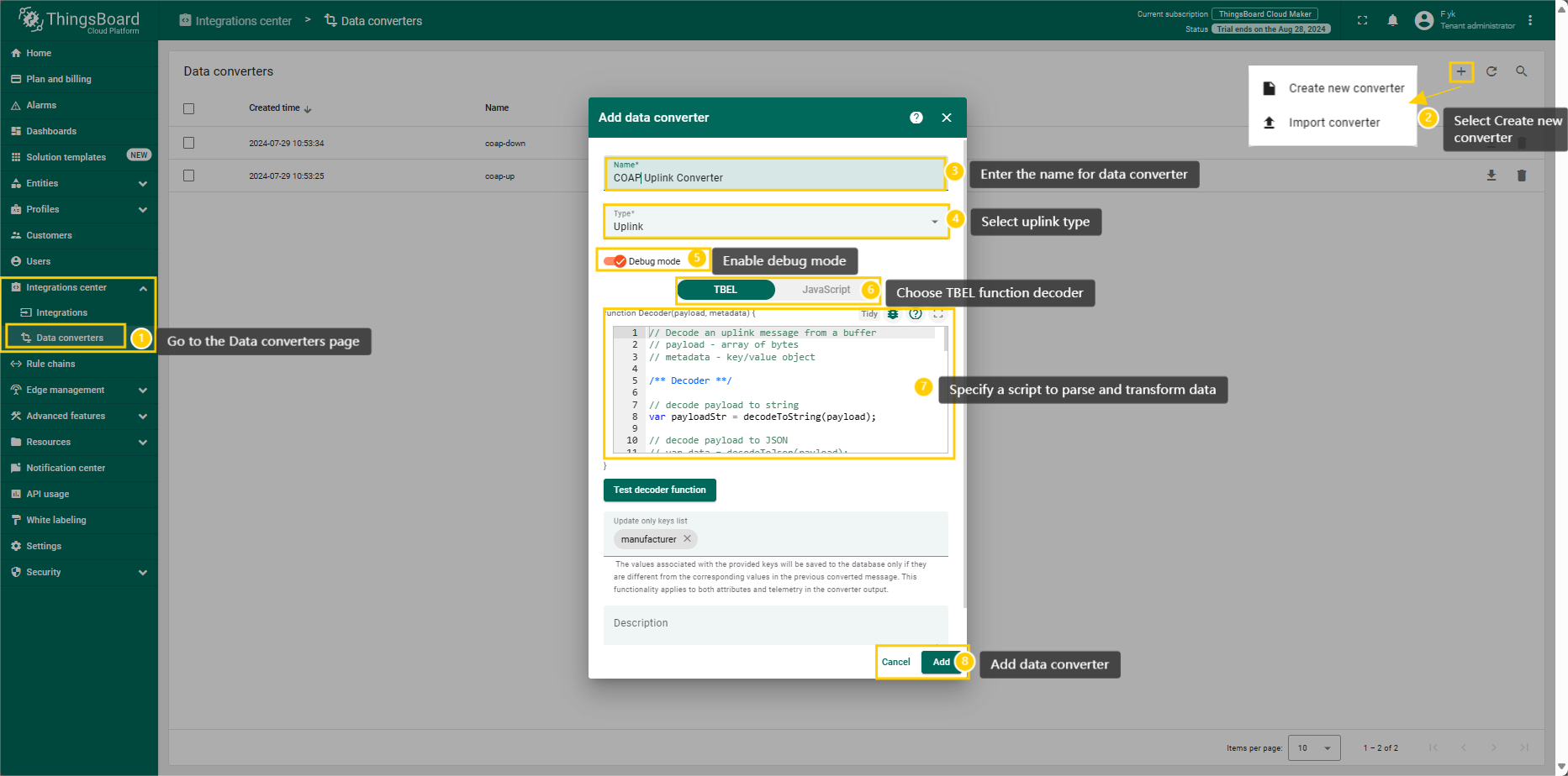
To create an uplink converter go to the Integrations center -> Data converters page and click “plus” button. Name it “COAP Uplink Converter” and select type "Uplink". Use debug mode for now.
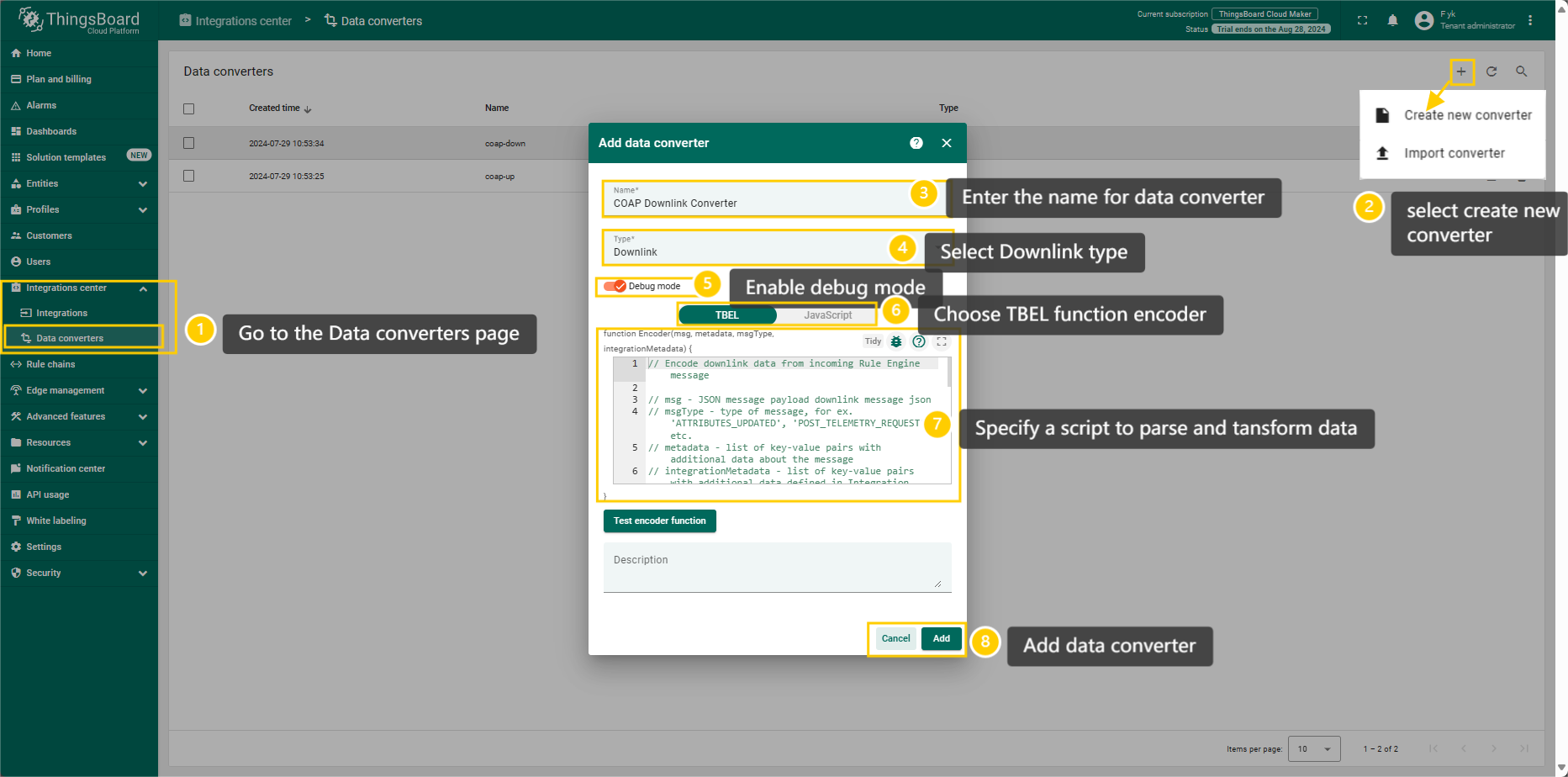
Downlink Converter
The Downlink converter transforming outgoing RPC message and then the Integration sends it to external COAP broker.
3.7.1.2 COAP Integration Setup
Go to the Integrations center -> Integrations page and click “plus” icon to add a new integration. Name it “CoAP Integration”, select type COAP ;
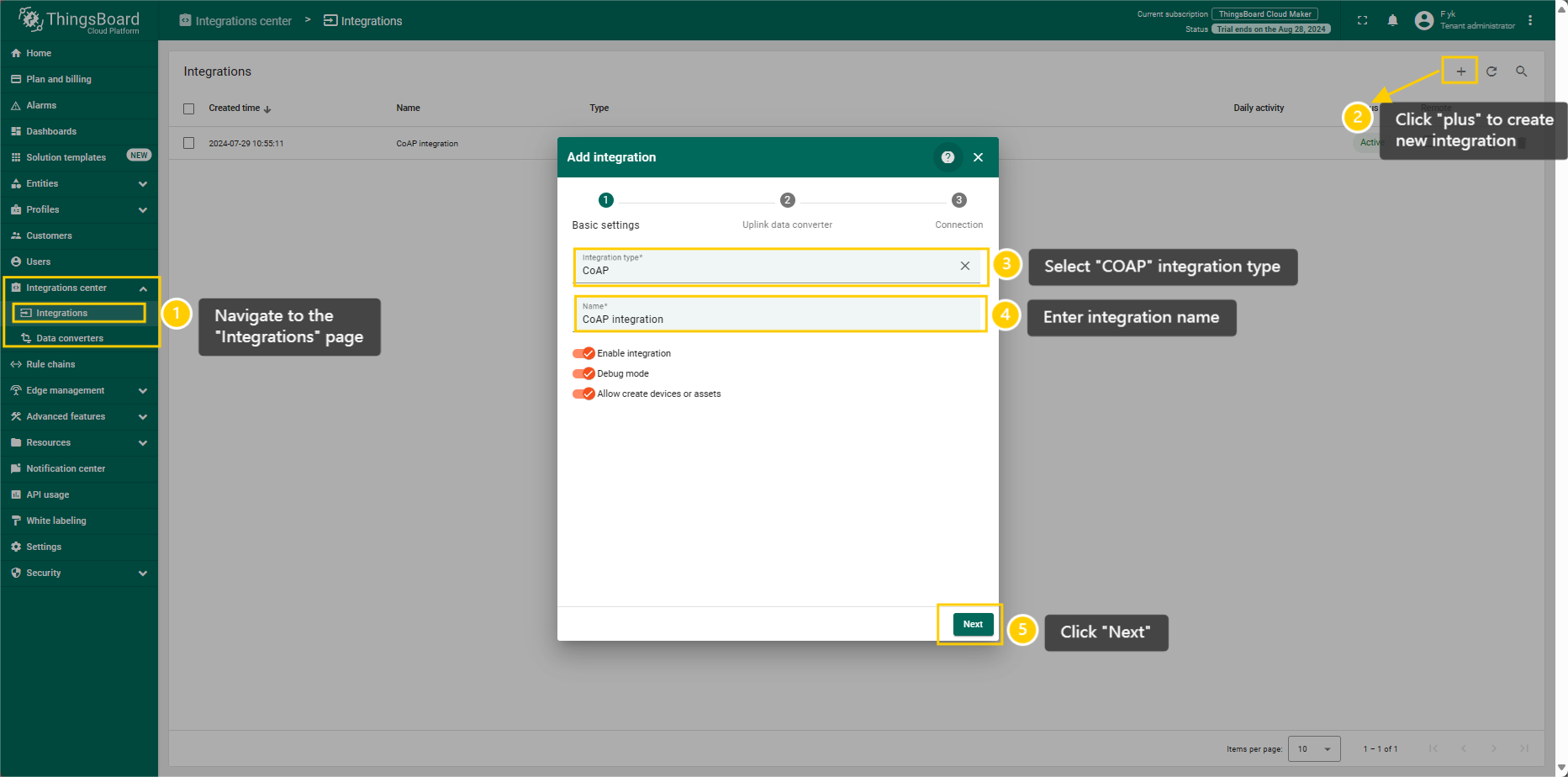
The next steps is to add the recently created uplink converters;
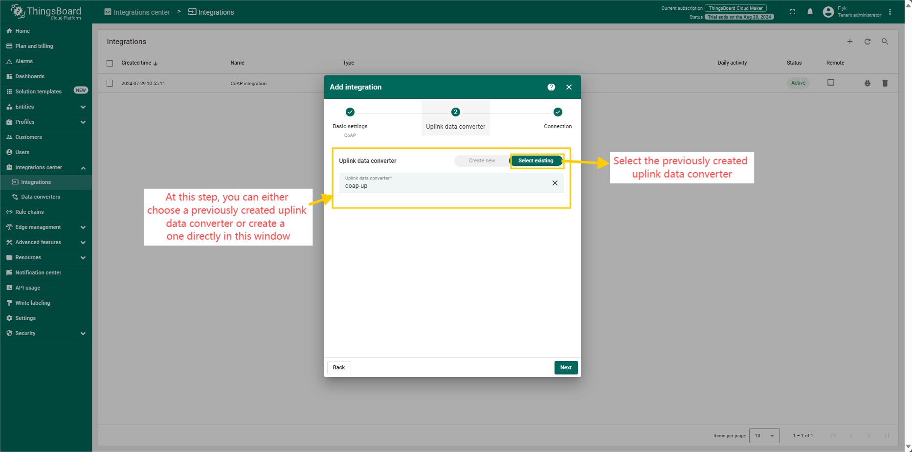
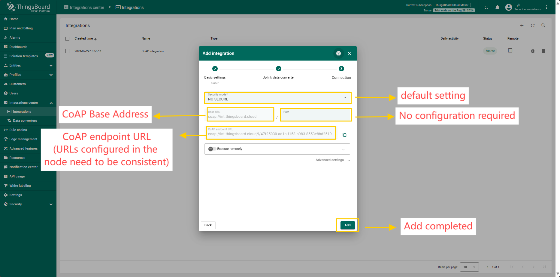
3.7.1.3 Add COAP Integration
3.7.2 Node Configuration(Example: Connecting to the Thingsboard platform)
3.7.2.1 Instruction Description
AT+PRO=1,0(HEXformat uplink) &AT+PRO=1,5(JSONformat uplink)AT+SERVADDR=COAPServer Address,5683
Example: AT+SERVADDR=int.thingsboard.cloud,5683(The address is automatically generated when the COAP integration is created)
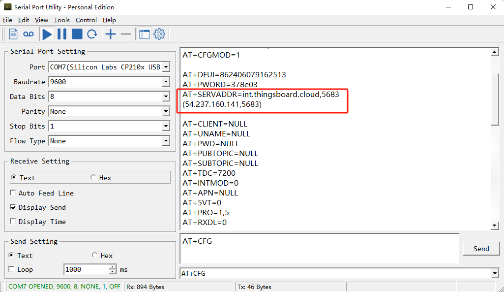
Note:The port for the COAP protocol has been fixed to 5683
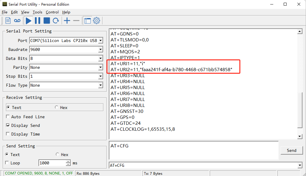
AT+URI1=11,"i"AT+URI2=11,"Needs to be consistent with the CoAP endpoint URL in the platform"
-CB devices using a BG95-M2 module, you need to configure TWO URL commands,
e.g.
AT+URI1=11, "i"AT+URI2=11,"faaaa241f-af4a-b780-4468-c671bb574858"
3.8 Tago.io (via MQTT)
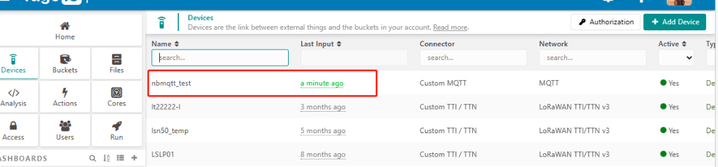
3.8.1 Create device & Get Credentials
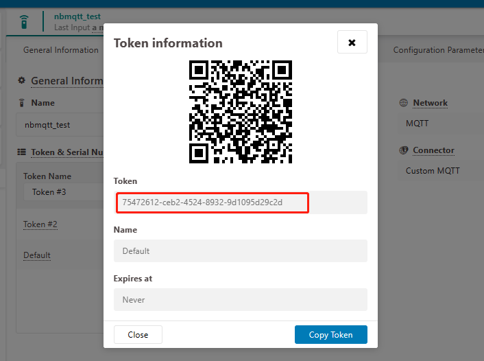
We use MQTT Connection to send data to Tago.io. We need to Create Device and Get MQTT Credentials first.
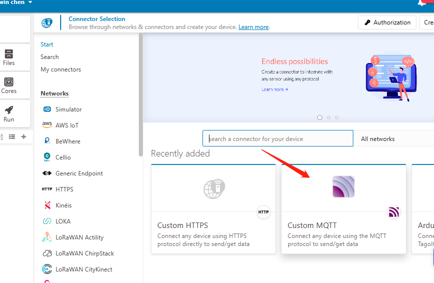
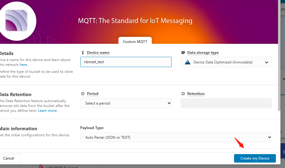
Go to the Device section and create a device. Then, go to the section tokens and copy your device-token.
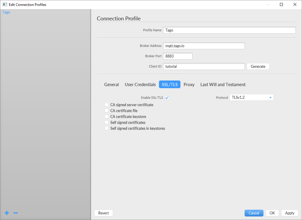
The device needs to enable the TLS mode and set the AT+TLSMOD=1,0 command.
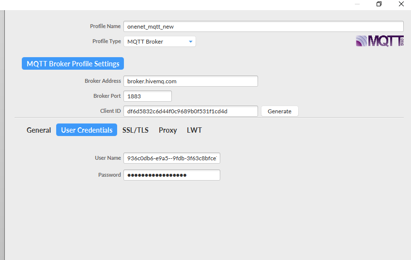
On the Connection Profile window, set the following information:
-
Profile Name: “Any name”
-
Broker Address: mqtt.tago.io
-
Broker Port: 8883
-
Client ID: “Any value” On the section User credentials, set the following information:
-
User Name: “Any value” // Tago validates your user by the token only
-
Password: “Your device token”
-
PUBTOPIC: “Any value”
-
SUBTOPIC: “Any value” AT command:
-
AT+PRO=3,0 or 3,5// hex format or json format -
AT+SUBTOPIC=<device name>or User Defined -
AT+PUBTOPIC=<device name>or User Defined -
AT+CLIENT=<device name> or User Defined -
AT+UNAME=<device name> or User Defined -
AT+PWD=“Your device token”
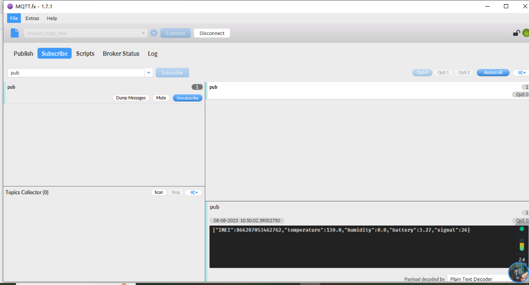
3.8.2 Simulate with MQTT.fx
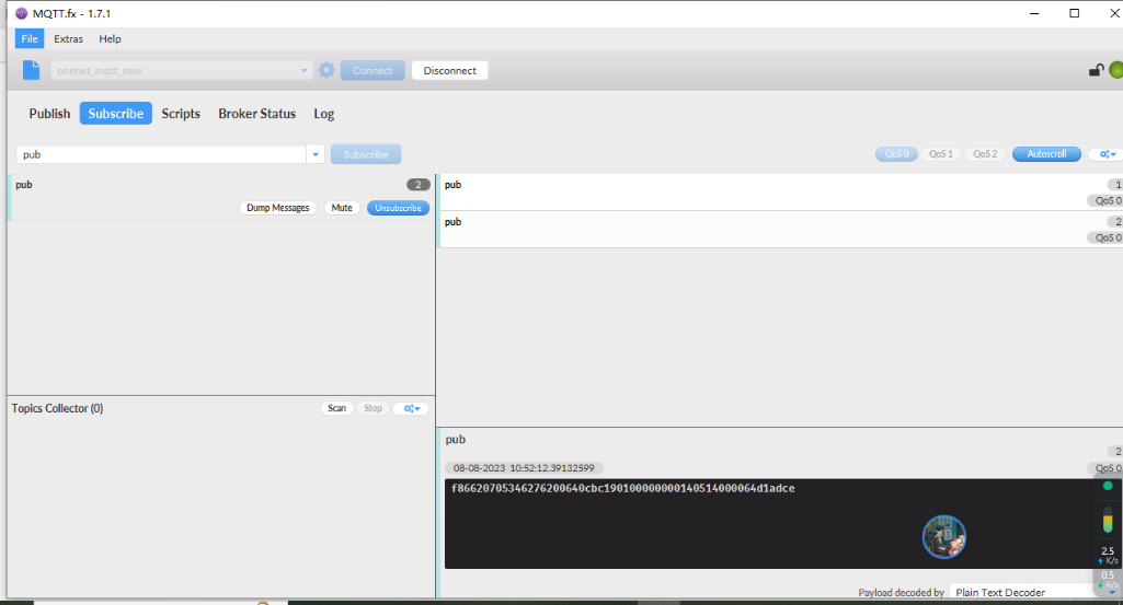
Users can run the AT+PRO=3,5 command, and the payload will be converted to JSON format.
3.8.3 tago data
3.9 TCP Connection
AT command:
-
AT+PRO=4,0// Set to use TCP protocol to uplink(HEX format) -
AT+PRO=4,5// Set to use TCP protocol to uplink(JSON format) -
AT+SERVADDR=120.24.4.116,5600// to set TCP server address and port
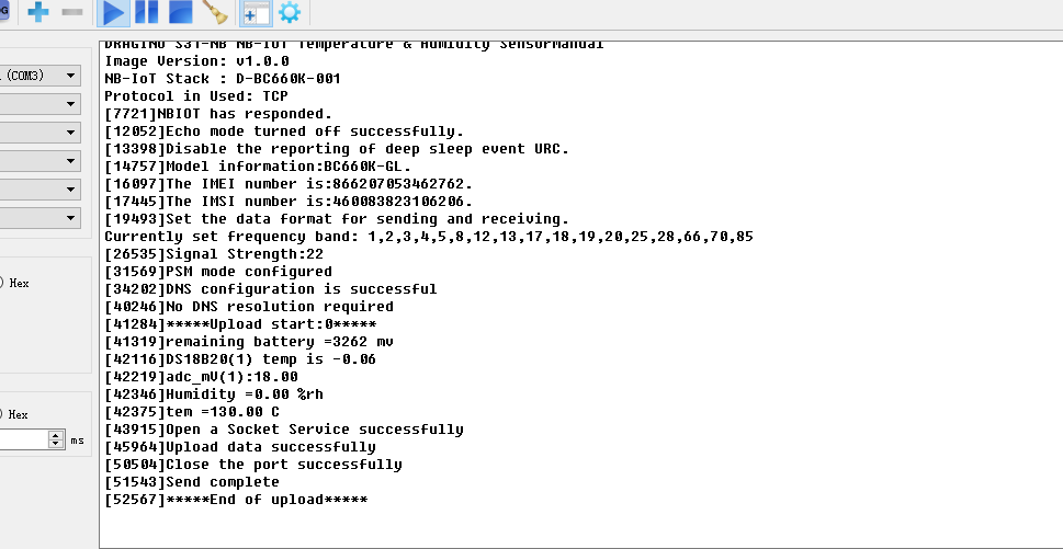
Sensor Console Output when Uplink:
See result in TCP Server:

3.10 AWS Connection
Users can refer to Dragino NB device connection to AWS platform instructions
3.12 ThingsEye (via MQTT)
3.12.1 Configure ThingsEye
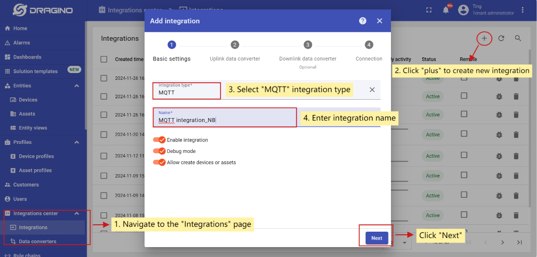
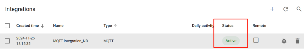
3.12.1.1 Create MQTT integration
Go to the Integrations center -> Integrations page and click “plus” icon to add a new integration. Name it “MQTT Integration_NB”, select type MQTT;
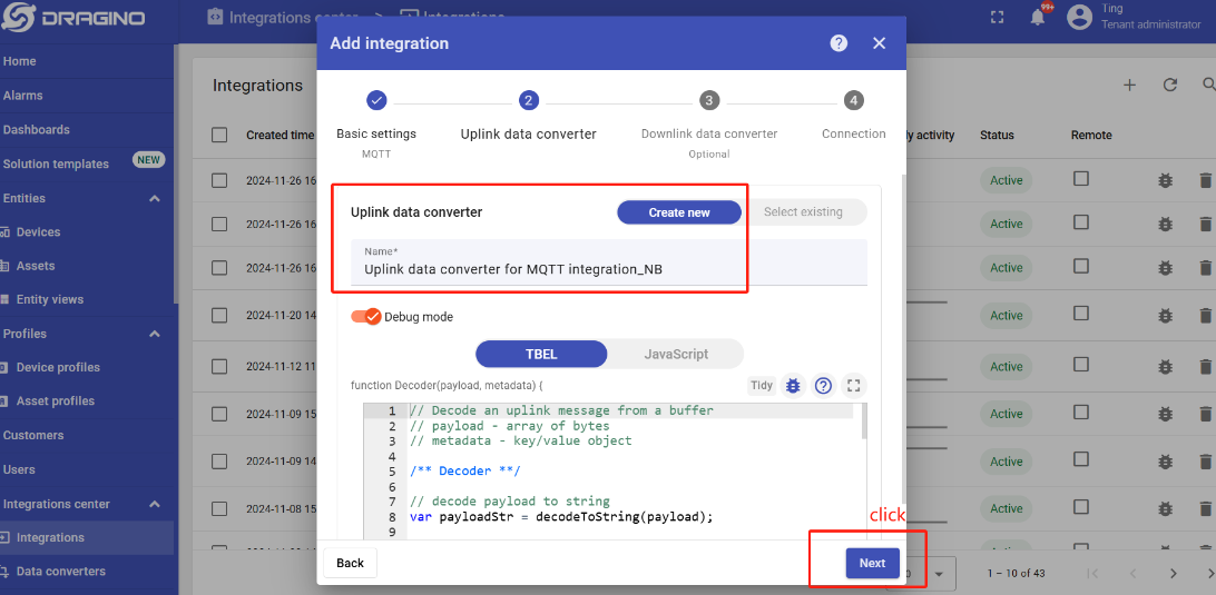
Next, directly select to create a new Uplink data converter and downlink data converter.
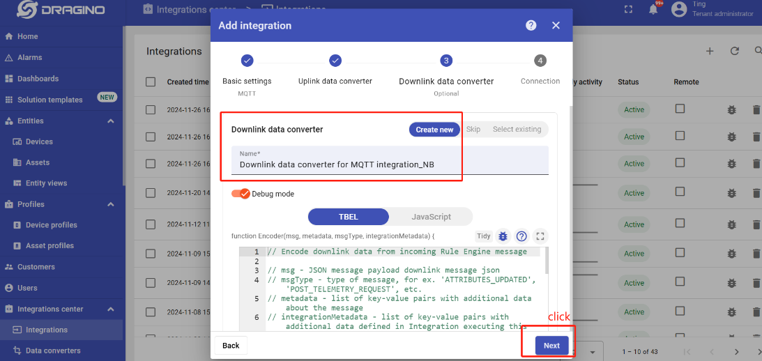
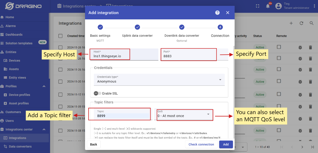
Add a topic filter:
Consistent with the theme of the node setting.
Note: Recommended MQTT broker: lns1.thingseye.io 8883, fixed use. Topic can be changed on their own, but it need to be consistent with the node's publish and subscribe topic.
You can also select an MQTT QoS level. We use MQTT QoS level 0 (At most once) by default;
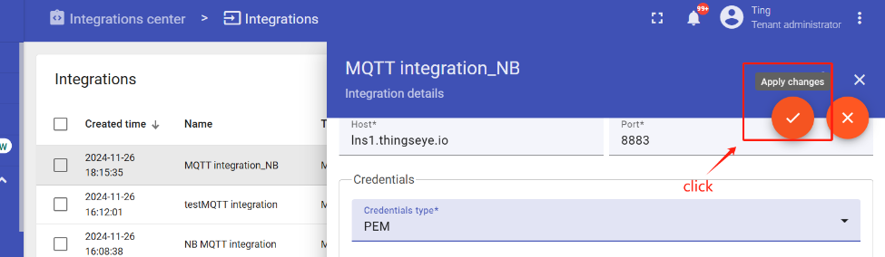
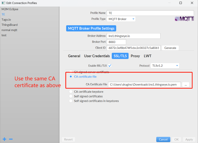
3.12.1.2 Add credentials to the MQTT integration
Click on the MQTT integration you just created.
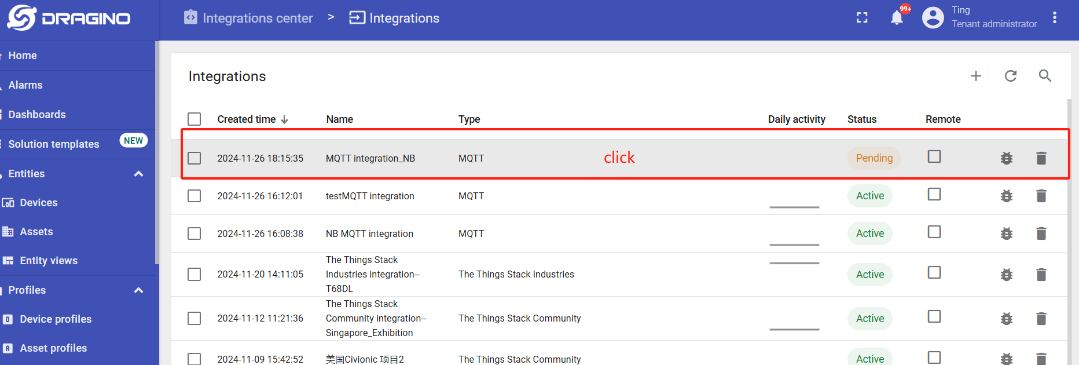
Click the edit icon in the upper right corner to enter the edit mode.
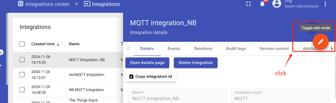
Add credential files.
Click this link to download the certificates.
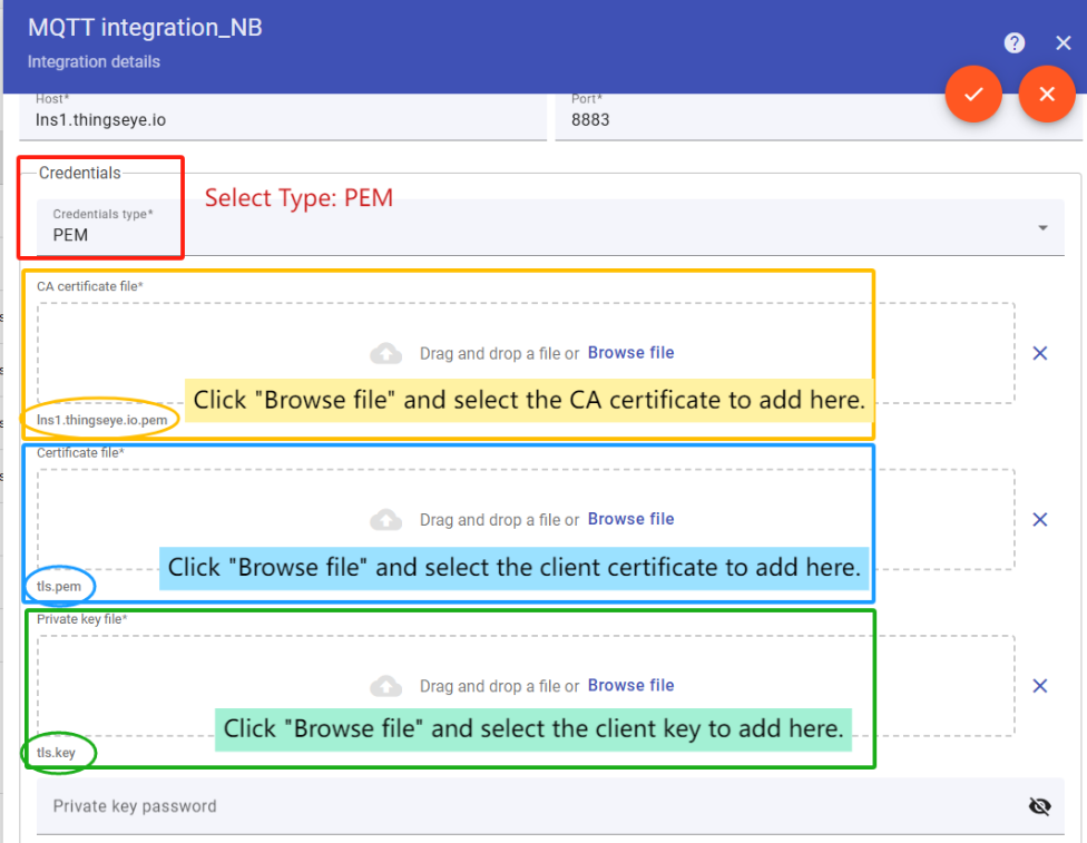
When the addition is complete, save the Settings.
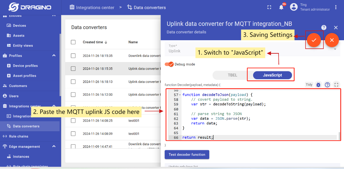
3.12.1.3 Setup uplink and downlink converters
First, you need to download the MQTT uplink/downlink JS code.
- Uplink Converter
The purpose of the decoder function is to parse the incoming data and metadata to a format that ThingsBoard can consume.
Go to the Integrations center -> Data converters page, and find that MQTT uplink converter that was newly created when the integration was created.
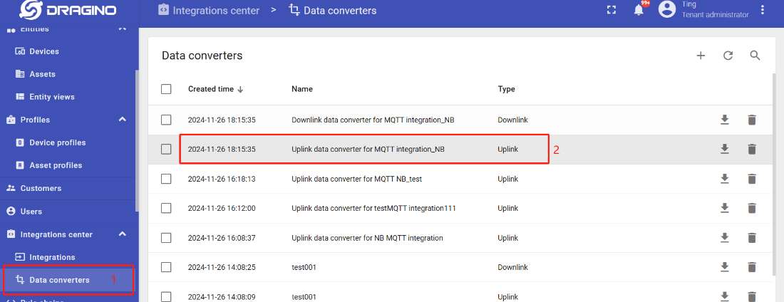
Enter edit mode and apply MQTT uplink JS code to this uplink converter.
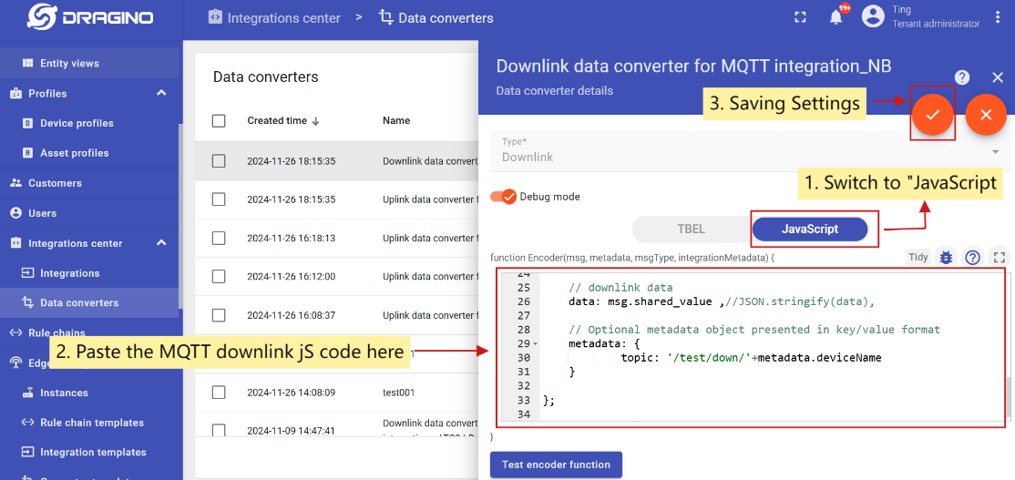
- Downlink Converter
Go to the Integrations center -> Data converters page, and find that MQTT downlink converter that was newly created when the integration was created.
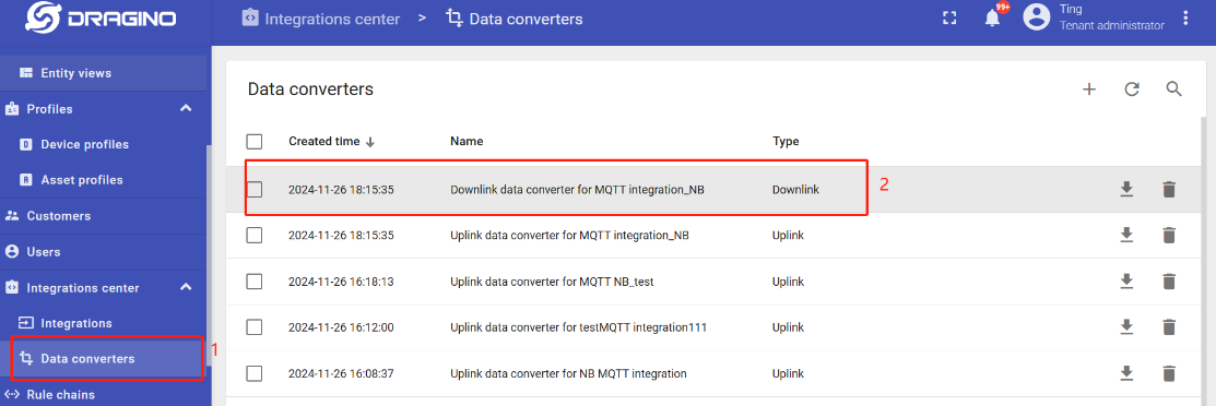
Enter edit mode and apply MQTT downlink JS code to this downlink converter.
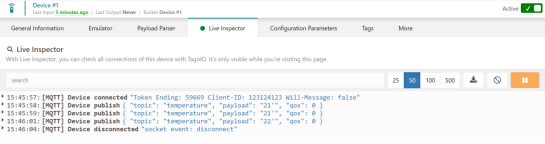
3.12.2 Simulate with MQTT.fx
3.12.3 Configure -CB node
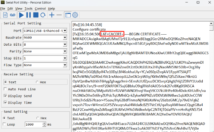
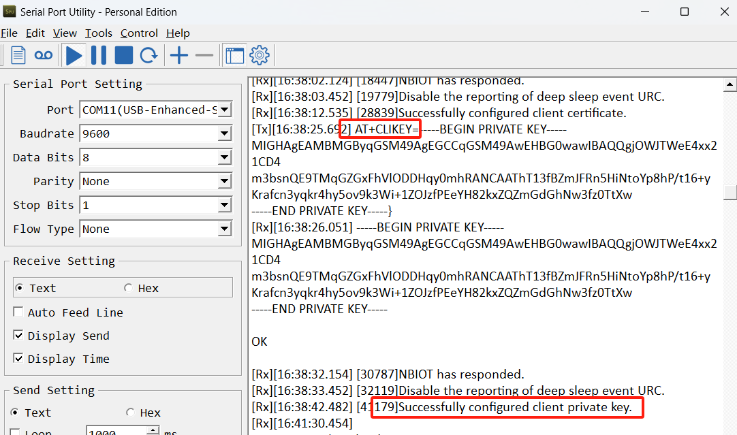
First you need to configure the certificate to the -NB node. Follow the instructions in this link to configure the certificate.
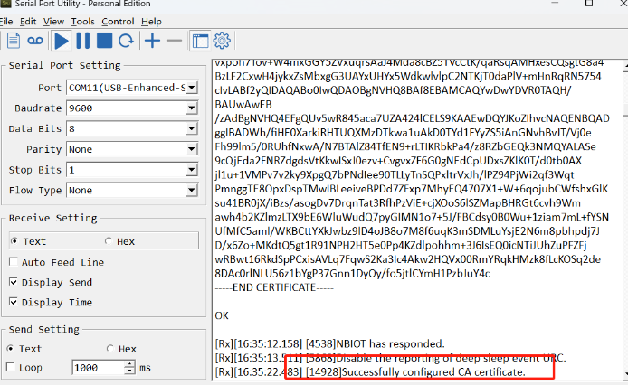
Screenshot of successful certificate configuration:
- Configuring the CA Certificate
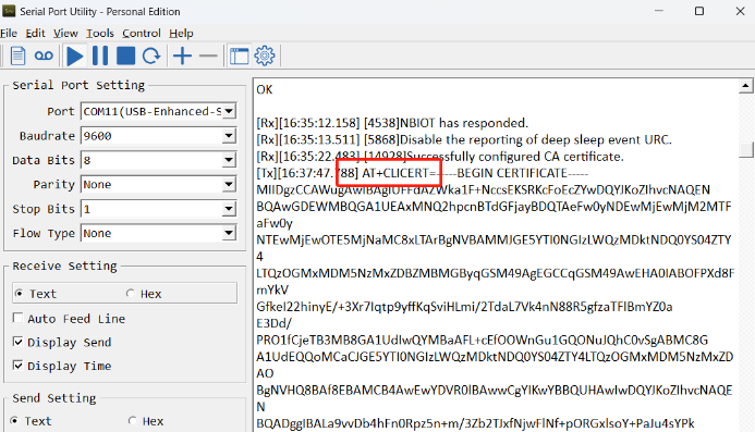
- Configure client certificate
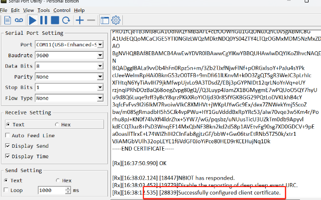
- Configure client private key
When the certificate is configured, burn the boot program, burn the working firmware, and then restart the device.
Then configure the -CB node to connect to the ThingsEye platform:
AT Commands
AT+PRO=3,5// Use MQTT Connection & Json PayloadAT+SERVADDR=lns1.thingseye.io,8883AT+SUBTOPIC=8899// Consistent with the Topic of MQTT integration created by ThingsEyeAT+PUBTOPIC=8899// Consistent with the Topic of MQTT integration created by ThingsEyeAT+CLIENT=NULLAT+UNAME=NULLAT+PWD=NULLAT+TLSMOD=1,2
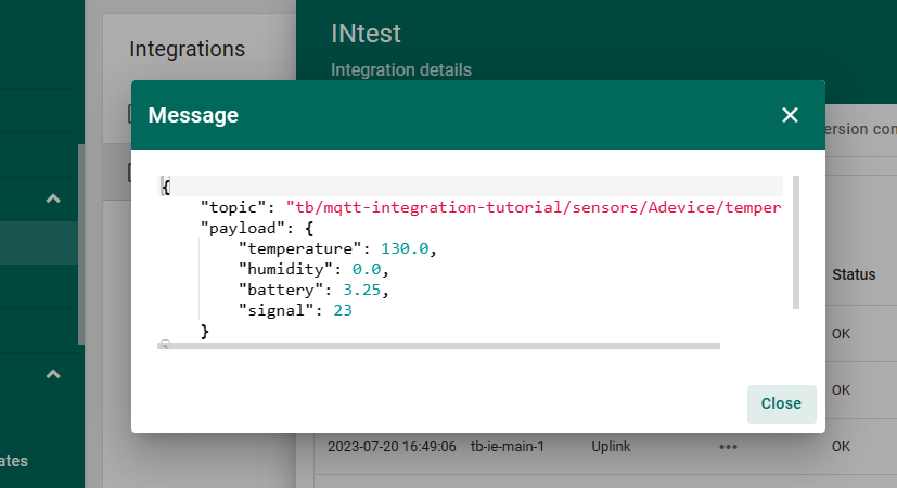
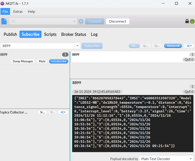
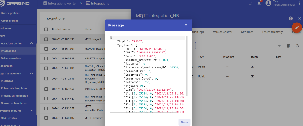
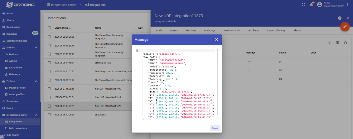
Test Uplink by click the button for 1~3 seconds, the MQTT integration in ThingsEye allows you to view the data upstream from the device:
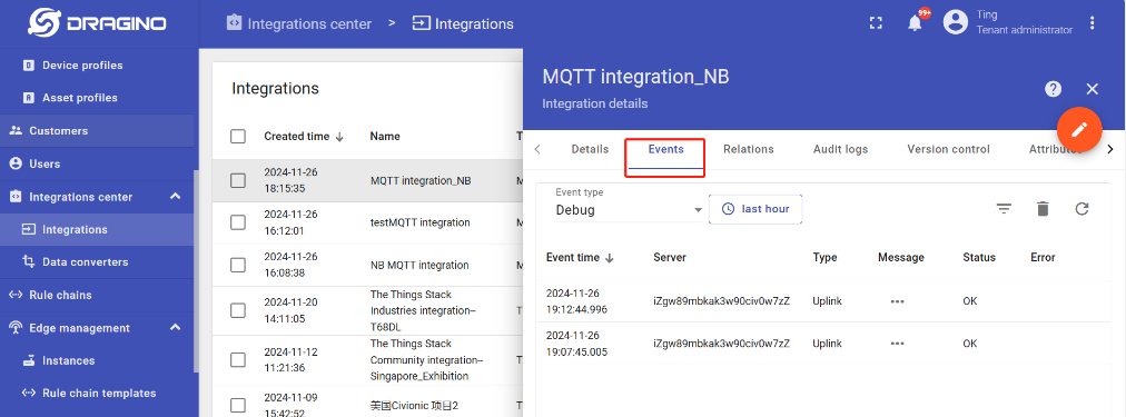
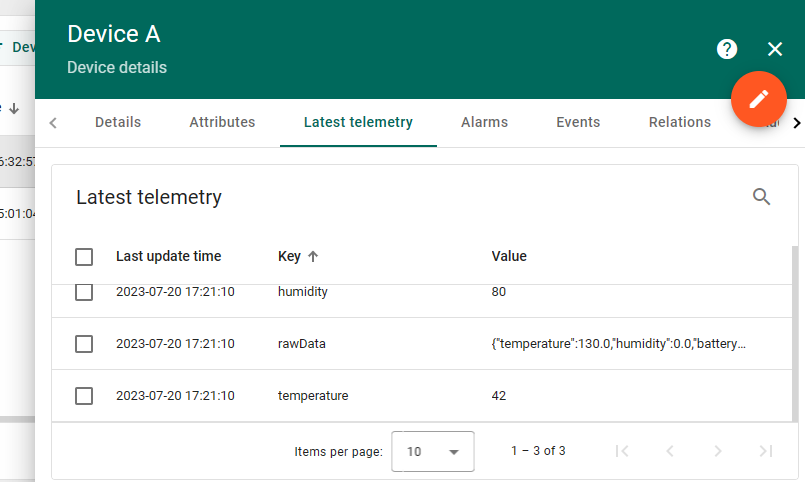
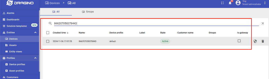
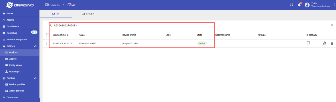
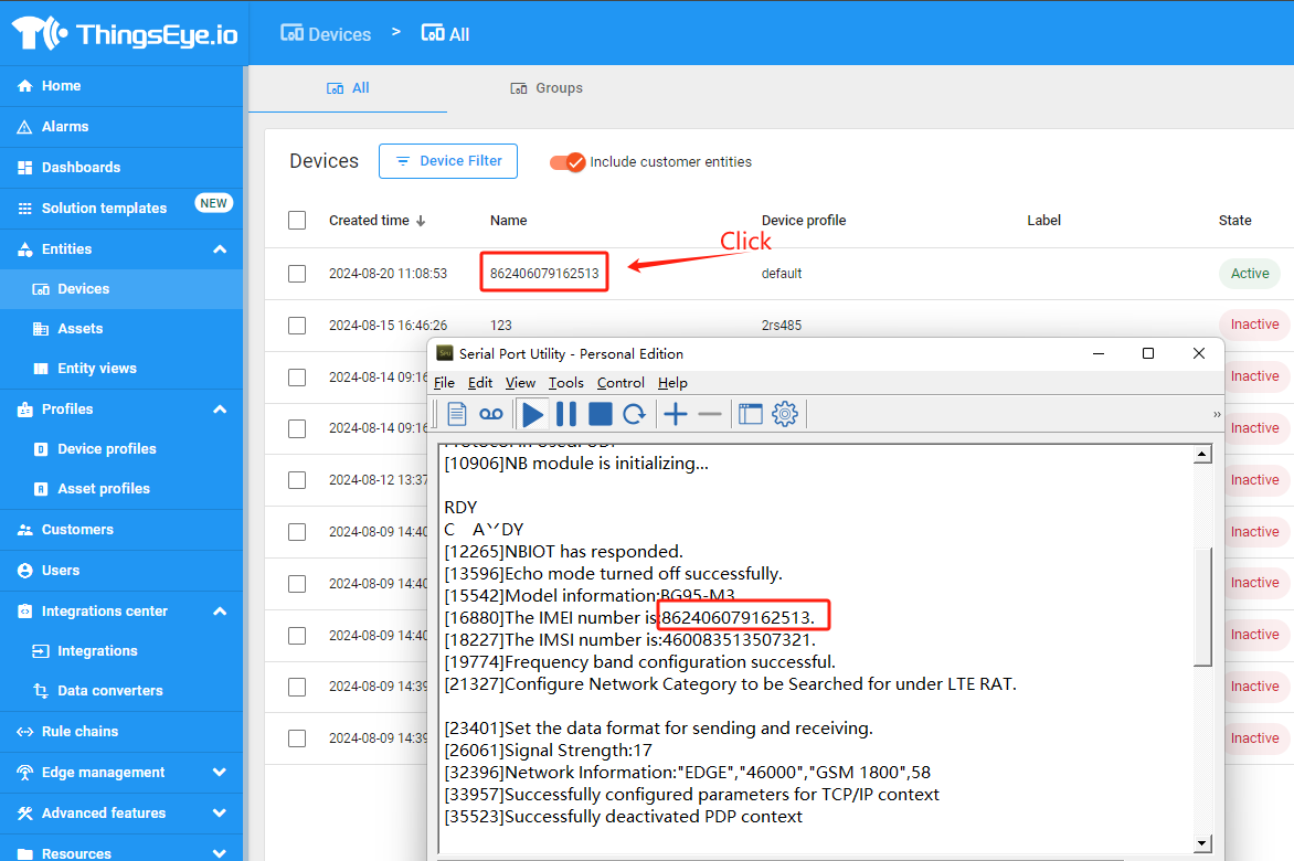
Go to "Device" -> "Search Device", enter the IMEI of the device to find the device.
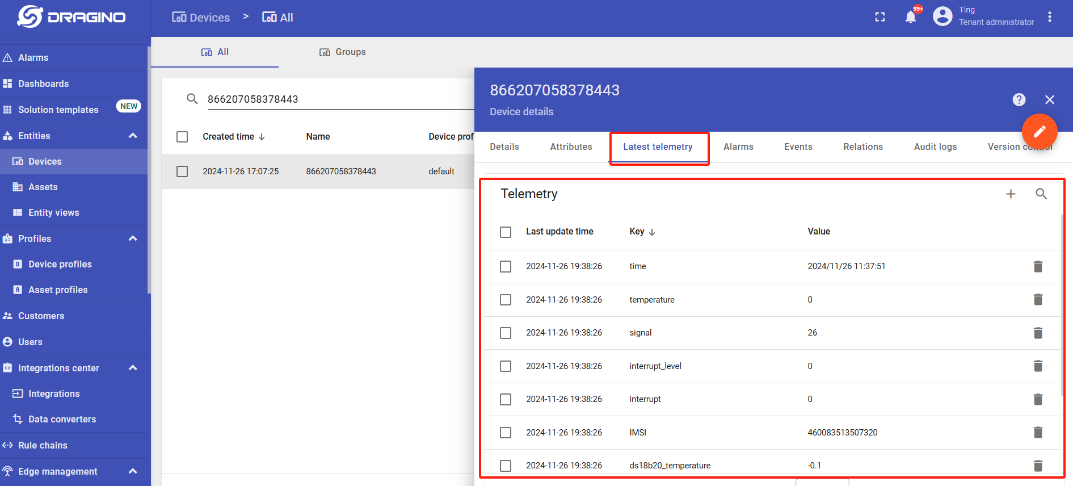
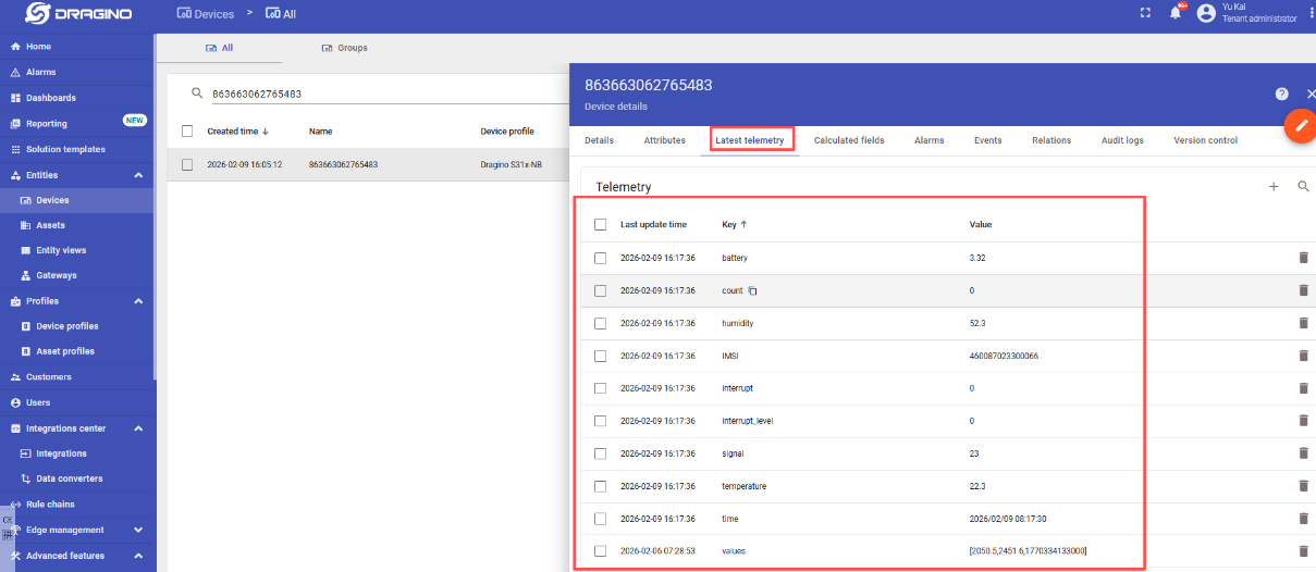
You can view the data that has just been uplink on the device:
3.12 ThingsEye (via UDP)
3.12.1 Configure ThingsEye
Note: 1. Since platform configuration involves port data forwarding, it will be handled by platform technicians. 2. Users only need to configure their NB devices and provide the NB device's “IMEI” to the platform technicians for port data forwarding to the corresponding user account.
3.12.2 Device Configuration
AT Commands
AT+PRO=2,5// Use UDP Connection & Json PayloadAT+SERVADDR=server1.thingseye.io,11560// Configure the UDP server domain name and port
Click the button for 1–3 seconds to test the uplink. ThingsEye's UDP integration feature allows you to view your device's upstream data.
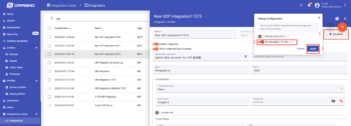
Note: Requires enabling the Debug Receive Data function within the UDP integration feature, which is disabled by default.
Select the corresponding UDP integration -> Click to enter the UDP integration configuration interface -> Click the button in the upper-right corner to enter edit mode -> Click "Debug mode" -> Open "All messages (15 min)" -> Click "Apply" to save
:
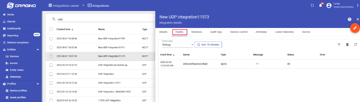
Test Uplink by click the button for 1~3 seconds, the UDP integration in ThingsEye allows you to view the data upstream from the device:
Go to "Device" -> "Search Device", enter the IMEI of the device to find the device.
You can view the data that has just been uplink on the device:
4. COAP/UDP/MQTT/TCP downlink
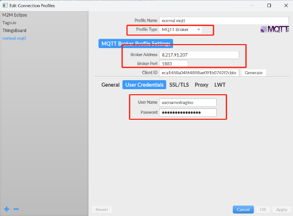
4.1 MQTT (via MQTT.fx)
Configure MQTT connections properly and send downlink commands to configure nodes through the Publish function of MQTT.fx_._
1. Configure node MQTT connection (via MQTT.fx):
AT command:
-
AT+PRO=3,0 or 3,5// hex format or json format -
AT+SUBTOPIC=User Defined -
AT+PUBTOPIC=User Defined -
AT+UNAME=<device name> or User Defined -
AT+PWD=<device name> or User Defined -
AT+SERVADDR=8.217.91.207,1883// to set MQTT server address and port
Note: To uplink and downlink via MQTT.fx, we need set the publish topic and subscribe topic different, for example: AT+SUBTOPIC=SE01\_SUB & AT+PUBTOPIC=SE01\_PUB.
2. When the node uplink packets, we can observe the data in MQTT.fx.

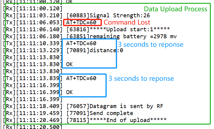
3. The downlink command can be successfully sent only when the downlink port is open.
The downlink port is opened for about 3 seconds after uplink packets are sent.
Therefore, when we see the node uplink packets in the Subscribe window, we need to immediately switch to the publish window to publish the hex format command.
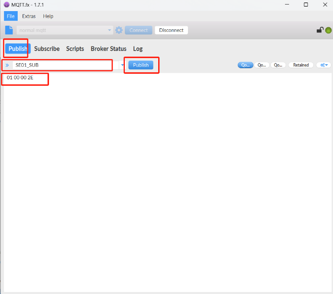
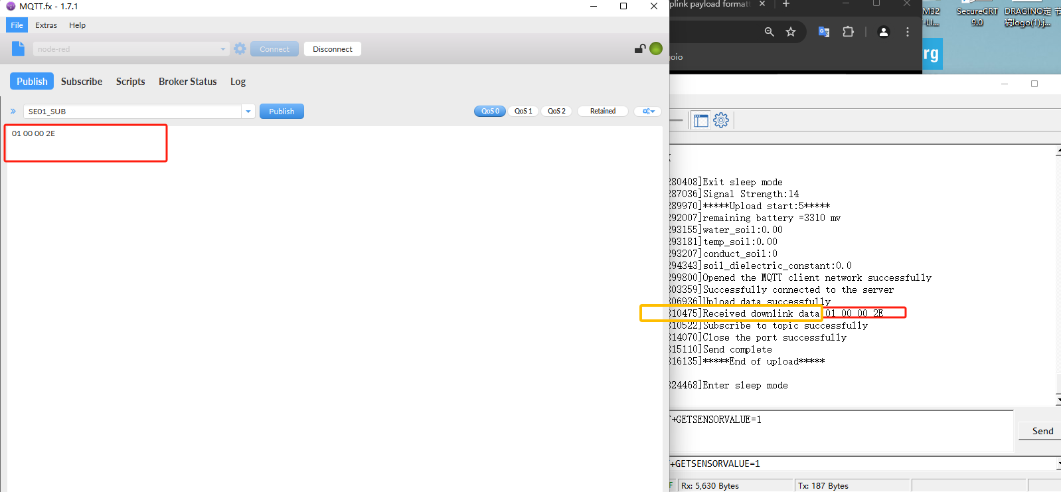
Note: Users can edit the hex command in advance. When the node uplink, directly click the publish button several times to increase the success rate of command configuration.
4.2 UDP (via Thingseye)
Note: The UDP service on the ThingsEye platform needs to be built by the user. (Description Link:UDP service building instructions)
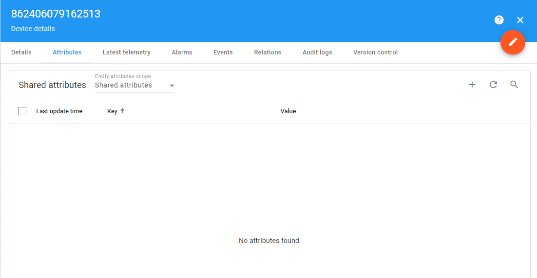
After the node is successfully connected to the platform, you need to select the corresponding node (you can refer to the node's IMEI to find it)
After clicking Show Node Details Page, Select Properties --- select Shared Properties --- click Add Properties
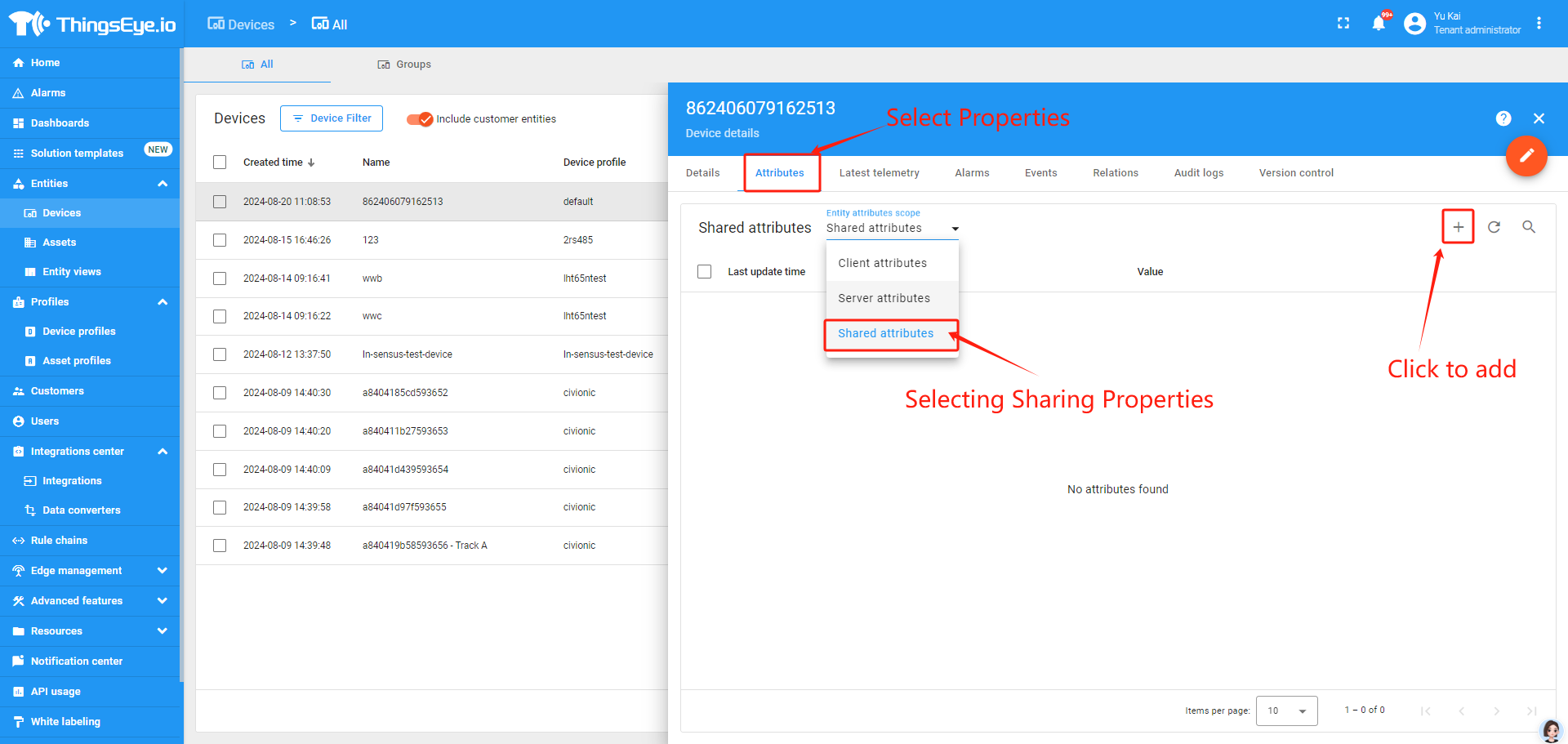
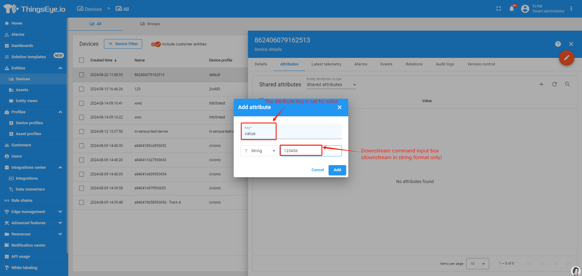
After clicking Add Shared Attribute, set the key to value, and write the command that needs to be downlinked in the Downlink Command Input box
(Note: Downlinks can only be downlinked in string format, otherwise the node will not recognize the downlink command.)
After the command is successfully added, the platform will send the command down on the node's next uplink.
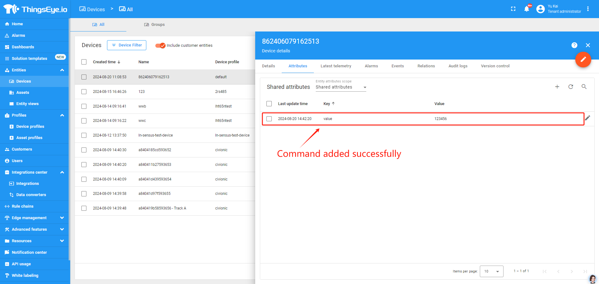
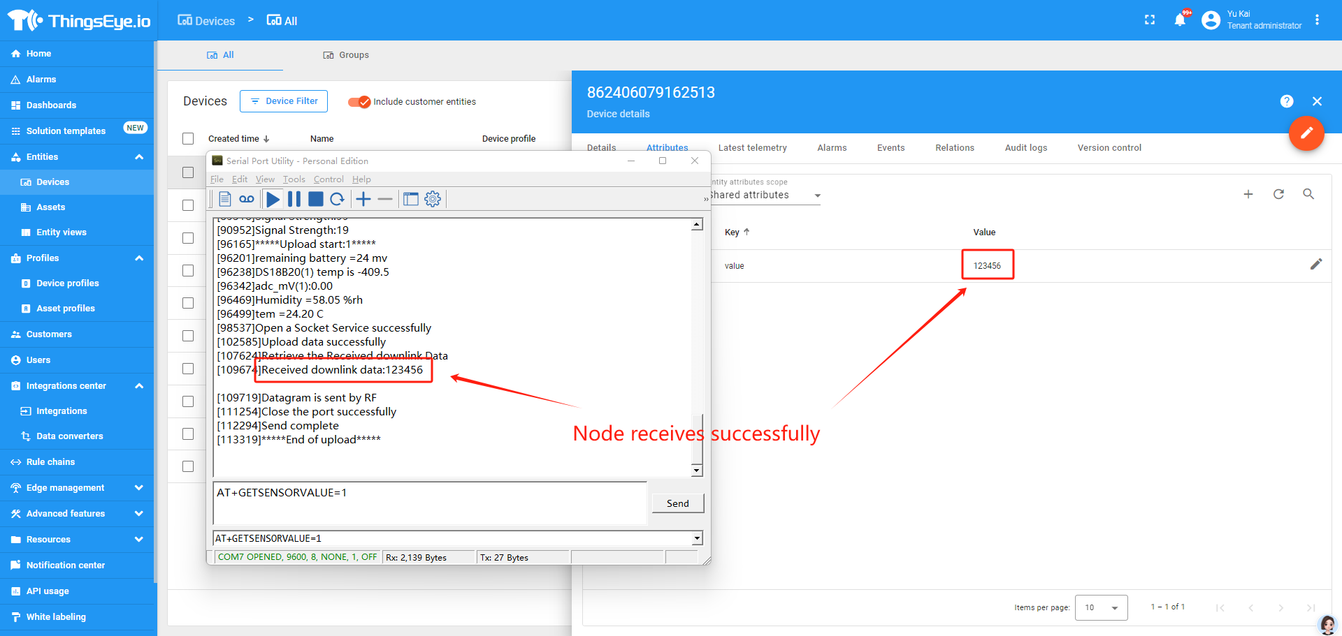
Upon successful issuance, the platform automatically eliminates the attributes from the queue and waits for the next addition of new attributes
5. GPS positioning function
1. Turn on GPS function
AT+GPS=1or 0 // GPS function on or off
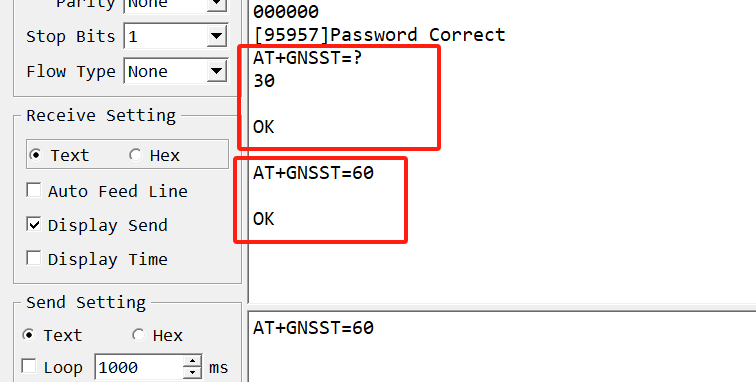
2. Extend the time to turn on GNSS
AT+GNSST=30 // GPS search for positioning information for 30 seconds
3. Get or set GPS positioning interval in units of hour
AT+GTDC=24 // The device will activate GPS positioning every 24 hours
6. FAQ
6.1 What is the usage of Multi Sampling and One Uplink?
The NB series has the feature for Multi Sampling and one uplink. See one of them
[http:///docs/wiki/nb-iot/rs485-sdi-12-sensor-nodes/sn50v3-nb/)
User can use this feature for below purpose:
- Reduce power consumption. The NB-IoT transmit power is much more higher than the sensor sampling power. To save battery life, we can sampling often and send in one uplink.
- Give more sampling data points.
- Increase reliable in transmission. For example. If user set
AT+TR=1800// The unit is seconds, and the default is to record data once every 1800 seconds (30 minutes, the minimum can be set to 180 seconds)AT+NOUD=24// The device uploads 24 sets of recorded data by default. Up to 32 sets of record data can be uploaded.AT+TDC=7200// Uplink every 2 hours.- this will mean each uplink will actually include the 6 uplink data (24 set data which cover 12 hours). So if device doesn't lost 6 continue data. There will not data lost.
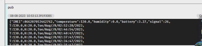
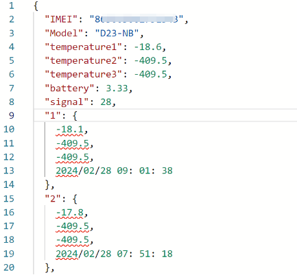
6.2 Why the uplink JSON format is not standard?
The json format in uplink packet is not standard Json format. Below is the example. This is to make the payload as short as possible, due to NB-IoT transmit limition, a standard Json is not able to include 32 sets of sensors data with timestamp.
The firmware version released after 2024, Mar will use change back to use Json format. Detail please check changelog.
7. Trouble Shooting:
7.1 Checklist for debuging Network Connection issue. Signal Strenght:99 issue.
There are many different providers provide NB-IoT service in the world. They might use different band, different APN & different operator configuration. Which makes connection to NB-IoT network is complicate.
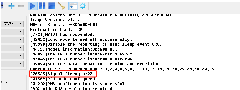
If end device successfully attached NB-IoT Network, User can normally see the signal strengh as below (between 0~31)
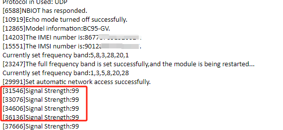
If fail to attach network, it will shows signal 99. as below:
When see this issue, below are the checklist:
- Does your SIM card support NB-IoT network? If SIM card doesn't not specify support NB-IoT clearly, normally it doesn't support. You need to confirm with your operator.
- Do you configure the correct APN? Check here for APN settings.
- Do you lock the frequency band? This is the most case we see. Explain and Instruction.
- Check if the device is attached to Carrier network but reject. (need to check with operator).
- Check if the antenna is connected firmly.
If you have check all above and still fail. please send console log files (as many as possible) to support@dragino.com so we can check.
7.2 Why sometime the AT Command is slow in reponse?
When the MCU is communicating with the NB-IoT module, the MCU response of AT Command will become slower, it might takes several seconds to response.
7.3 What is the Downlink Command Format for CB Devices?
We strongly recommend that users upgrade their -CB device firmware to the latest protocol stack version (D-BG95-003 or later).
The latest firmware introduces a unified downlink command format which simplifies device configuration and ensures compatibility across different platforms.
For all details regarding the new standard format, please refer to: 8.2.7 Standard JSON Downlink Format
7.4 What if the signal is good but the domain name resolution fails?
If the domain name resolution fails, first check whether the domain name is correct, users can use their own website domain name resolution tool to verify the domain name.
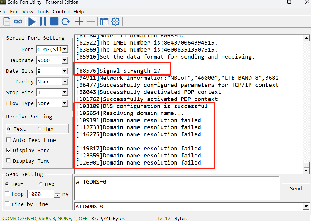
If the domain name is correct, but the domain name cannot be resolved, the user can turn off the domain name resolution function(AT+GDNS=1 and use the domain name communication directly.
- Set the DNS
AT Command: AT+GDNS
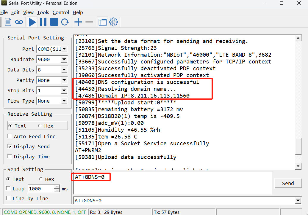
AT+GDNS=0 // Default. Automatically resolves the domain name and uses the resolved IP to communicate.
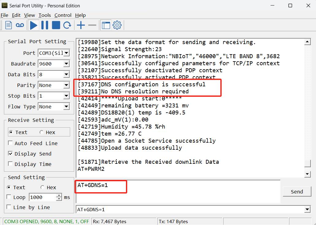
AT+GDNS=1 // Disabling Domain name resolution. Use the domain name directly to communicate.
Note: For -CB products, with the exception of AT+PRO=2,5,all protocols and payload formats support direct domain communication.
Example:
7.5 GPS debugging
Indoor GPS signal is very weak, outdoor positioning is generally recommended.
7.5.1 GPS commands
The following are three related AT commands that introduce GPS functions.
- Turn on/off GPS AT Command:
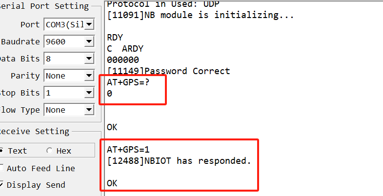
AT+GPS
Ex1: AT+GPS=0 // Turn off GPS
Ex2: AT+GPS=1 // Turn on GPS
Downlink command: 0x11
Format: Command Code (0x11) followed by 1 byte.
Example: Downlink Payload: 11 01 // AT+GPS=1
- Set GNSS open time
Extend the time to turn on GNSS. The automatic GPS location time is extended when the node is activated.
AT Command: AT+GNSST
Example: AT+GNSST=30 // Set the GPS positioning time to 30 seconds
Downlink command: 0x10
Format: Command Code (0x10) followed by 2 bytes.
Example: Downlink Payload: 10 00 1E // AT+GNSST=30
- Set GPS positioning interval
Feature: Set GPS positioning interval (unit: hour).
When GPS is enabled, the node automatically locates and uplinks each time it passes GTDC time after activation.
AT Command: AT+GTDC
Example: AT+GTDC=24 // Set the GPS positioning interval to 24h.
Downlink command: 0x12
Format: Command Code (0x12) followed by 3 bytes.
Example: 24 hours: 24(D)=0x18(H)
Downlink Payload: 12 00 00 18 // AT+GTDC=24
7.5.2 GPS workflow
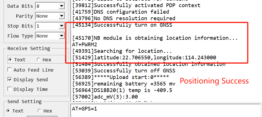
The whole working process after the GPS function is enabled(AT+GPS=1) is as follows:
1. When activate the node, the node will turn on the GNSS, if the GPS signal is good, the node will print and upload the position information with the first data packet immediately.
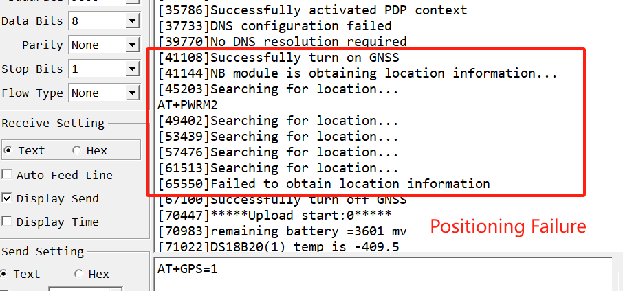
If the signal is not good, it may take the whole GNSST time but still can not search the latitude and longitude information, at this time the node uploads the latitude and longitude all to 0.
So if there is a failure of positioning, the user can extend the GNSST time appropriately.
2. Each TDC time node is not repositioned and the positioning interval is determined by the AT+GTDCtime.
The latitude and longitude payload uplinked at each TDC time is the GPS positioning information from the previous GTDC time.
Only when the node is activated or every GTDC time is reached, the node turns on the GNSS and we can observe the GPS search information through the serial assistant or Bluetooth tool.
7.5.3 GPS debugging methods
In summary, we can deduce the methods of debugging GPS:
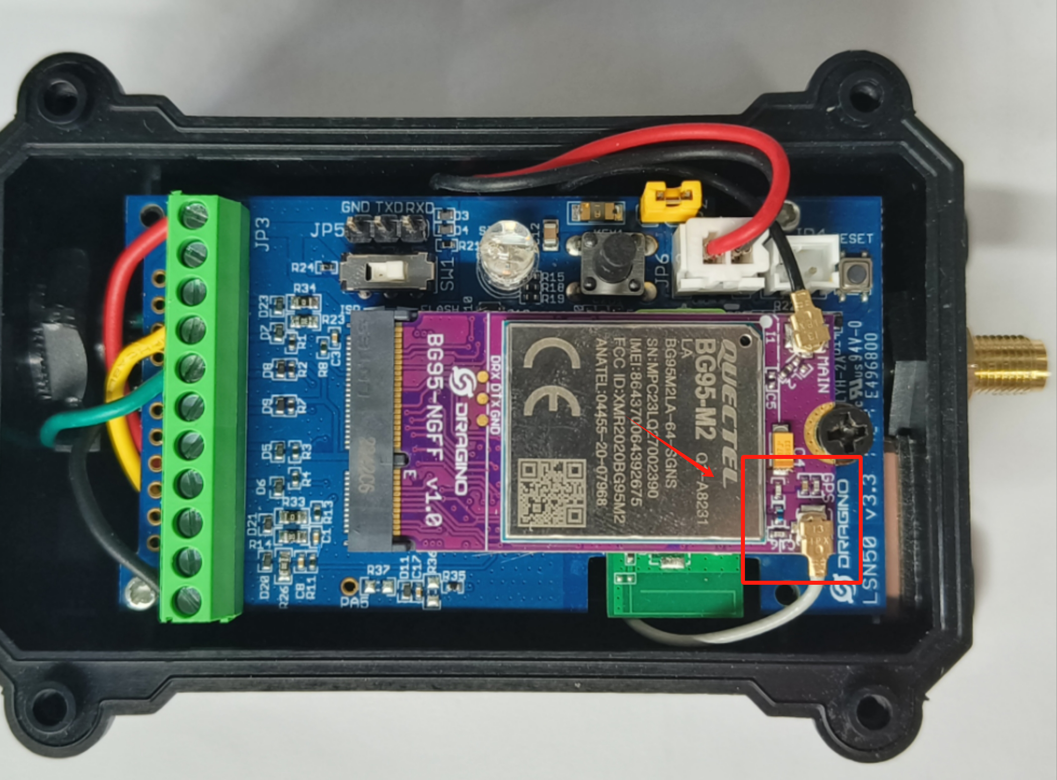
- Check whether the GPS function is enabled.
- Check whether the GPS antenna is loose.
If the GPS antenna is loose, the GPS signal is weak, and the positioning fails.
- Use the
AT+GNSSTcommand to extend the positioning time.
The default AT+GNSST=30,that is, the default positioning time is 30 seconds.
If the location fails, users can extend the location time.
7.6 CB device configuration TCP/IP failed
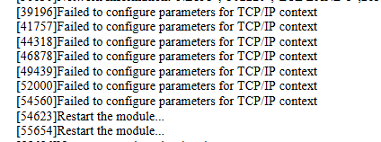
Use AT+IPTYPE=?to check the IPTYPE configuration.
AT+IPTYPEcan only be configured as 1 or 2.
If it is configured otherwise, this error will occur
7.7 How to get the debug log for further analyze?
CB model use the same debug instruction as NB model. Please check this link:
8. LTE-M Stack Changelog (BG95-M2/M3)
8.1 002 Protocol Stack Update Content
8.1.1 Network access display
Feature: When the device successfully joins the network, it will print Network Information in the startup log.
Device response format: Network Information:"NBIoT","Operator Information","BAND","Channel"
Example:
Network Information:"NBIoT","46000","LTE BAND 8",3682
8.1.2 Format AT+SERVADDRcommand
Feature: Automatically delete spaces entered during configuration to prevent users from entering the wrong address.
Example:
Send command: AT+SERVADDR=broker. hivemq. com,1883
During the writing process, extra spaces in the command will be removed before writing to the device.
as follows:
AT+SERVADDR=broker.hivemq.com,1883
8.1.3 Downlink Platform -- TE
Feature: Support for UDP downlink on the TE platform, with the addition of the command AT+DOWNTE
AT command: AT+DOWNTE Command Example Function/Parameters Response/Explanation
AT+DOWNTE=?
Get current Settings
0,0 (default)
OK
AT+DOWNTE=a,b
a: Set the conversion between the downlink of the standard version and 1T version
0: Set the downlink of the standard version.
1: Set the downlink of the 1T version(ThingsEye platform)
b: Enable/Disable downlink debugging
0: Disable downlink debugging mode.
1: Enable downlink debugging mode, users can see the original downlink reception.
Example:
AT+DOWNTE=0,1// Set to standard version downlink, and enable downlink debugging.AT+DOWNTE=1,1// Set to 1T version downlink, and enable downlink debugging.
Downlink Command:
No downlink commands for feature
8.1.4 Preventing unexpected restarts
Features: The device enters sleep mode by pressing the button five times consecutively after leaving the factory. To prevent accidental crashes or resets, a deep sleep flag is programmed. If the device is unexpectedly reset and restarted, it will re-enter deep sleep mode. A hardware reset will also put it into deep sleep mode.
Exit sleep mode: The only way is to send a reset command via serial port or press and hold the ACT button for 5 seconds to reset the device software.
8.1.5 DNSCFG command removes format restrictions
Features: The AT+DNSCFGcommand has been expanded from 19 characters to 40 characters, removing format restrictions.
8.1.6 Add IMSI
Feature: Adds an IMSI field to the upstream payload.
8.1.7 GPS Positioning Time
Features:
1. Changed the default positioning duration from 30 seconds to 60 seconds.
2. Added a GPS toggle switch. When GPS is enabled, it prints the Fix timeout and GPS positioning information during the positioning process.
8.1.8 Interrupt Logic
Features:
1. When INTMOD=1, interrupt_level is set to 1 upon rising edge triggering and to 0 upon falling edge triggering.
2. When INTMOD=2, interrupt_level is set to 0 upon falling edge triggering.
3. When INTMOD=3, interrupt_level is set to 1 upon rising edge triggering.
8.1.9 Network access interval
Features:
The first four network access requests are timed at TDC intervals. After four consecutive failures, the request interval doubles to twice the TDC duration.
8.1.10 Increase current time
Feature: The current sampling time is added to the current data payload in the JSON uplink format.
8.2 003 Protocol Stack Update Content
8.2.1 Get stack version downlink
Notice: This command is only valid for JSON uplink format.
Feature: You can easily identify the NB-IoT protocol stack version on your device by sending the following JSON-formatted command through the device's connection platform:
Taking the MQTT protocol as an example:
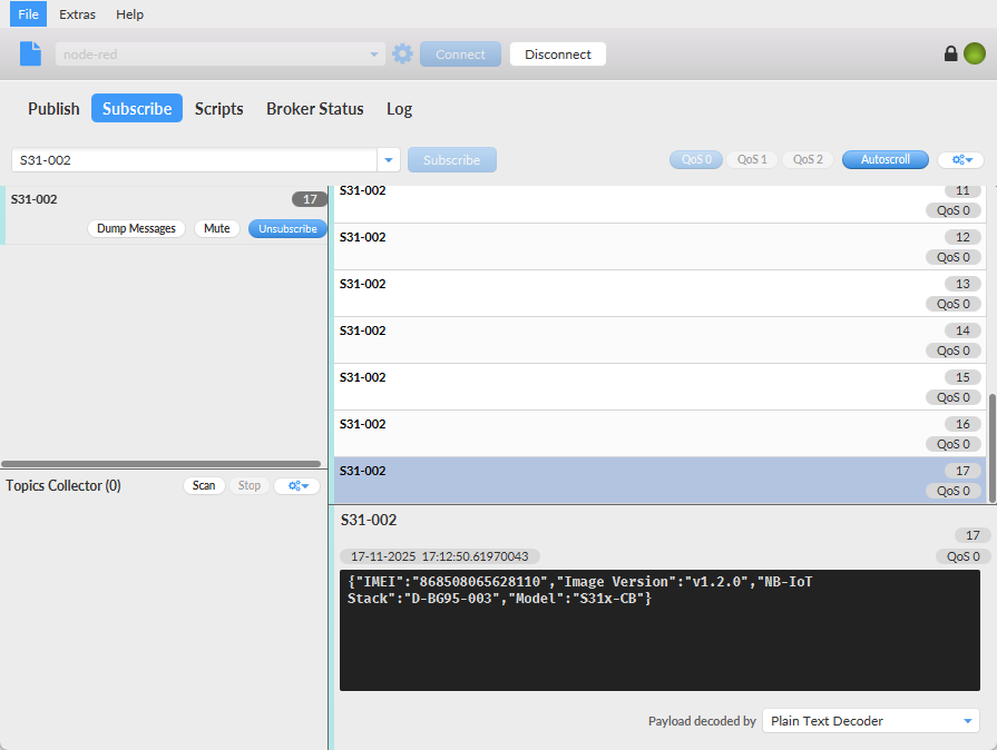
Platform downlink command ** : Event:Status
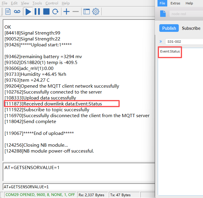
After receiving the downlink data, the device will perform another uplink query to check the device version after the current data packet has been sent, as shown in the figure below:
Device response format:
{"IMEI":"868508065628110","Image Version":"v1.2.0","NB-IoT Stack":"D-BG95-003","Model":"S31x-CB"}
8.2.2 Configure an NTP server
Feature: This command can change the NTP server to a local NTP server, thereby obtaining the local time for time synchronization.
Notice:
- When the SIM card cannot synchronize its time with the default NTP server, it will automatically synchronize with the NTP server configured using this command.
AT command:
-
AT+NTP="s1a.time.edu.cn"// Configure the time synchronization server as s1a.time.edu.cn Downlink command: Notice: This command is only valid for JSON uplink format. -
AT Format: {"Config":"[
AT+NTP="s1a.time.edu.cn"\"}
8.2.3 Specify a SIM carrier
Feature: This feature automatically configures the carrier each time a packet is sent, preventing the device from being unable to find a signal and thus being unable to send packets due to the loss of the operator code.
AT command:
AT+QCOPS=46000// Configure the carrier code to China Mobile's MCC and MNC.
Downlink command: Notice: This command is only valid for JSON uplink format.
- Downlink Format: {"Config":"[
AT+QCOPS=46000\"}
8.2.4 Increase stack size
Feature: In complex task scenarios, the device will not reset or malfunction due to stack overflow.
For example:
quickly and continuously execute multiple AT commands: configuration, query, fast uplink transmission, etc.
8.2.5 Fixed signal over-limit bug
Feature: During communication (such as before data upload), the device can correctly acquire and report the signal strength, and the reported CSQ value is within a reasonable defined range.
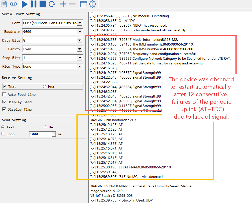
8.2.6 Automatic reset function
Feature: The device will automatically perform a software reset function when it continuously detects no signal (Signal Strength: 99) for 12 consecutive TDC cycles.
8.2.7 Standard JSON Downlink Format
Features: Unified JSON downlink format across all -CB products for consistent command delivery.
8.2.7.1 JSON Downlink Format Specification
{"Config":"[ATcommand1;ATcommand2;...ATcommandX]"}
- Config: Fixed key indicating a configuration command sequence.
- Value: A string containing AT commands separated by semicolons (;) within square brackets.
Examples:
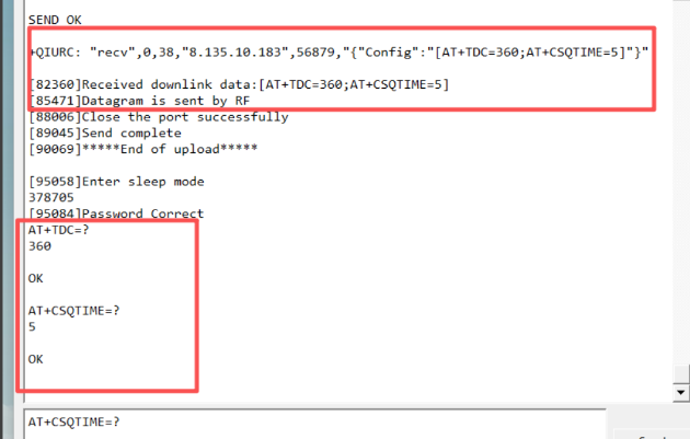
① Basic Configuration
For settings that take effect immediately (e.g., updating reporting intervals): {"Config":"[AT+TDC=360;AT+CSQTIME=5\]"
// This sets the periodic uplink interval (AT+TDC) to 360 seconds and the signal search attempt duration (AT+CSQTIME) to 5 minutes.
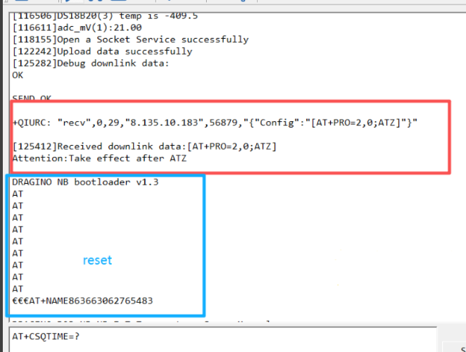
② Configuration Requiring Device Reset
For commands that require a device restart to apply (e.g., changing the server address or protocol), you must append the reset command ATZat the end:
{"Config":"[AT+SERVADDR=xxx.xxx.xxx.xxx,yyyy;ATZ\]" {"Config":"[AT+PRO=2,0;ATZ\]"
//The ATZcommand ensures the device reboots and the new settings take effect.
8.2.7.2 Important Notes on HEX Command Format
① Standard HEX Downlink
When sending individual AT commands in their HEX-encoded format (as defined in the command reference), send them directly as a single HEX string.
Example:
AT+TDC=300corresponds to 0100012C Send: 0100012C
 ② Special Case for ThingsBoard Platform
To enable HEX-format downlink commands on the ThingsBoard platform (AT+PRO=2,3), you must configure AT+DWONTE=1,1.When this configuration is active, any HEX-format downlink command must be wrapped in curly braces {}.
Example: To send the HEX command 0100012C in this mode, the downlink format must be: {0100012C}
//This ensures proper parsing by the ThingsBoard platform and the device's firmware.
8.2.8 ACK and data retransmission:
Note:The SN5OV3-CB, WSQ-CB, WSC2-C and WSC2-COMPASCT-CS products do not include this function.
Function: The datalog function for MQTT, TCP, and UDP protocols determines whether a signal or received ACK warrants a retransmission.
New command: AT+REDPT
When AT+REDPT=1,and the device does not receive an ACK response from the server, the device will automatically retransmit the data packet for which no ACK was received when it subsequently receives an ACK.
Note: 1. The retransmitted upstream format is the same as the datalog format; both are HEX format upstream. 2. If the UDP server the user is connected to does not have automatic downlink ACK functionality, the server will receive an automatic downlink ACK confirmation when an uplink packet is received. The downlink command format is: Confirm=200. (Confirm=200 is only visible when downlink debugging is enabled, i.e., AT+DOWNTE=0,1) 3. The Confirm=200 command only applies to the UDP protocol and is invalid for MQTT and TCP protocols. 4. When Confirm=200 is sent downlink simultaneously with other commands, the user needs to ensure that Confirm=200 is sent downlink first.
8.2.9 Json Format Downlink ACK feedback
Function: After the device successfully executes a downlink command in JSON transmission mode, this function will automatically send an ACK confirmation data packet containing the device's IMEI to the platform. As long as a reply is uploaded, the device has definitely received and processed the downlink command.
Note: 1. This feature is only available in JSON transport mode. 2. UDP servers do not automatically send downlink ACKs because the UDP protocol specification does not define ACK. Whether or not acknowledgment is required is added by the application developer; the device command specification is: Confirm=200. This command only applies to the UDP protocol.
Triggering requirement:
Any command in JSON format sent from the platform.
Device response format:
{"IMEI":"863663069842558","Downklink_Ack":"success"}
8.2.10 Domain Name Communication
Feature: This command is used when certain platforms only support connection via domain names. When set to 1, the domain name configured by the AT+SERVADDRcommand will not be resolved; instead, the connection to the platform will be established directly using the domain name.
AT command: AT+SNI Command Example Function/Parameters Response/Explanation
AT+SNI=?
Get current Settings
0 (default)
OK
AT+SNI=a
Set parameters
0: Disable Domain Direct Connect.
1: Enable Domain Direct Connect.
Example:
AT+SNI=0// Disable Domain Direct Connect.AT+SNI=1// Enable Domain Direct Connect.
Downlink command: Downlink format: {"Config":"[AT command"]"}
For example:
{"Config":"[AT+SNI=1"\"}
Note: This line is only valid when the preceding line is in JSON format.
8.3 004 Protocol Stack Update Content
8.3.1 Over-the-Air (OTA) Firmware Update
Feature: Added support for Over-the-Air (OTA) firmware updates. Devices with external SPI Flash can now receive firmware updates remotely without physical access.
Implementation: OTA functionality is triggered via downlink command F9 01 or AT command AT+UPGRADE.
Related Documentation: For detailed OTA setup and usage instructions, refer to: OTA Update Firmware for NB-IoT/LTE-M End Nodes
8.3.2 TLS Certificate Write Function
Feature: Added support for writing TLS certificates directly using the device firmware. Previously, writing TLS certificates required a dedicated firmware tool (a special program for certificate writing). Now, certificates can be configured directly using standard AT commands within the working firmware.
Related Documentation: For detailed certificate writing instructions, refer to: TLS Certificate Configuration Guide
8.3.3 Serial Log Upload (GETLOG)
Feature: Added AT+GETLOG=1 command and corresponding downlink command F8 01 to upload saved serial port logs to the server.
Command Type
Command
Behavior
AT Command
AT+GETLOG=1
Device will upload saved serial logs after the next data packet
JSON Downlink
{"Config":"[AT+GETLOG=1\]"}
Device immediately uploads saved serial logs
HEX Downlink
F8 01
Device immediately uploads saved serial logs
8.3.4 MQTT QoS Level Default Change
Feature: Changed default MQTT QoS (Quality of Service) level from 2 to 0.
Command: AT+MQOS
Setting
Description
AT+MQOS=0(default)
QoS 0 - At most once delivery (no acknowledgment)
AT+MQOS=1
QoS 1 - At least once delivery (acknowledgment required)
AT+MQOS=2
QoS 2 - Exactly once delivery (highest reliability, higher power consumption)
Impact: This change reduces network traffic and improves power efficiency for standard sensor data transmission. For applications requiring guaranteed delivery, users can set AT+MQOS=1or AT+MQOS=2.
8.3.5 DNS Resolution Optimization
Feature: Optimized DNS domain name resolution mechanism to improve reliability and prevent resolution failures.
Details: Internal improvements to the DNS resolution process reduce the likelihood of resolution errors, ensuring more stable connectivity when using domain names for server addresses.
Related Command: AT+BKDNS (enhanced for better error handling)
0
Toggle the left panel column.