MQTT Forward Instruction
1. Introduction
Dragino LoRa/LoRaWAN gateway support MQTT forwarding. It can forward the sensor data from LoRa network to MQTT server , and vice verse.
1.1 Support Devices
This MQTT forward instruction is for below devices:
- LG01N, OLG01N (Warning: LG01-P LG01-S use another instruction: MQTT for LG01-P/LG01S)
- LG02, OLG02
- MS14 series if installed with the same firmware. (in this case, the MQTT forward will work , but no LoRa support)
- LG308N, DLOS8N, LPS8N
- LPS8V2
The MQTT Client Utility used in Dragino is mosquitto_pub and mosquitto_sub. User can add more options to the mqtt commands.
Check out this link for more mosquito-related directives https://mosquitto.org/man/mosquitto_pub-1.html
2. Example to communicate to a simple MQTT server
2.1 Overview
This section is an example to show how to set up LG01-N to communicate with a MQTT server. The MQTT server is a simple utility set up in a local PC. Note: User can set up same server via this instruction.
2.2 Simulate via MQTT.fx utility
The MQTT.fx is a MQTT client tool. We can use this to simulate a MQTT connection to our MQTT broker first to make sure the MQTT broker works. This will also help us understand how it works.
In this test, the MQTT broker and MQTT.fx are installed in the same PC, so the MQTT server address in MQTT.fx should be localhost. Below shows how to connect to the server.
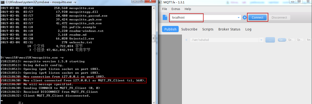
Connect to MQTT Broker
After connected, use publish to public some thing to MQTT server. This to simulate upsteam
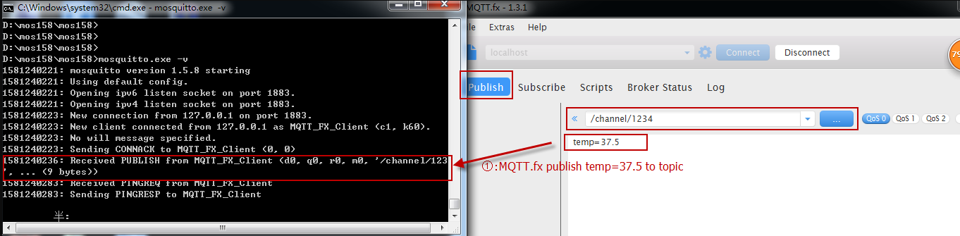
Upstream: Publish message to MQTT Broker
To simulate a downstream, use MQTT.fx to subscribe a topic, and publish something to this topic. as Below:
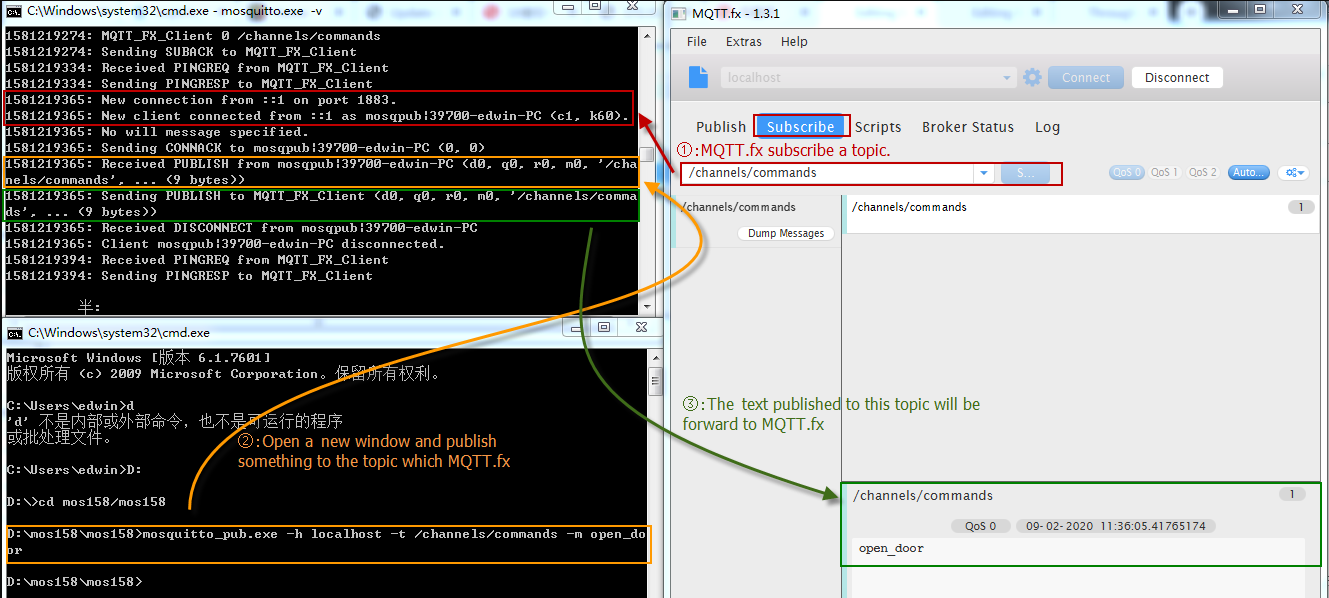
Downstream: Subscribe a topic to get downstream
3. Add LoRa support to communicate with remote sensor
In above section, we have configured the UI to support MQTT upstream and downstream. We can simulate via Linux command. In this section, we will guide how to communicate with remote LoRa End Node for upstream and downstream.
3.1 Use LoRa Raw protocol for communication -- For LG01/LG02
We can use LoRa Shield to send LoRa Raw data to Gateway and receive data from gateway.
The example Sketch for LoRa Shield +Arduino is here: LoRa_Shield_Sketch_For_MQTT
And this link is the required library: arduino-LoRa-master. Unzip this library and put in Arduino library location.
What does the Arduino Sketch do? The Arduino Sketch will:
- Upstream: Keep sending a LoRa Message every minutes with this payload : <4567>tem=xx&hum=yy (Where xx and yy are temperature and humidity value generated randomly).
- Downstream: Listening broadcast message from gateway, and print it in console.
- The LoRa parameter settings in Arduino should match the LoRa settings in gateway, as below:
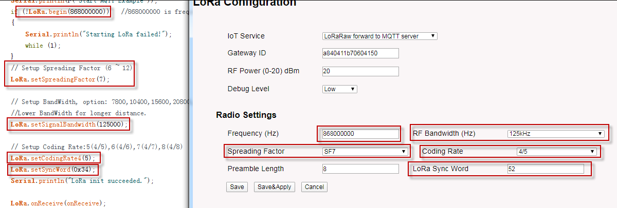
LoRa Parameter should match
Below is the test result after the Arduino Sketch is running.
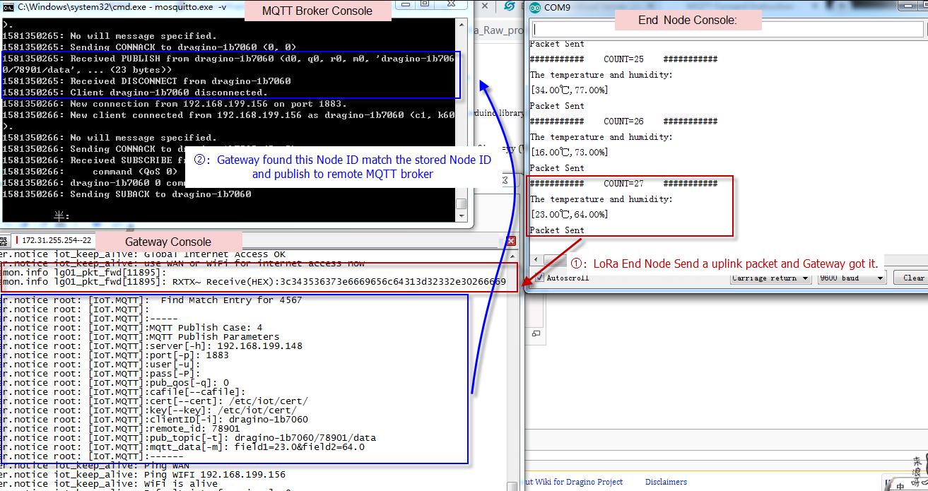
Upstream Data Flow

Downstream Data Flow
3.2 Use LoRaWAN Protocol for communication -- For LG308/LPS8/DLOS8/LG308N/LPS8N/DLOS8N
Since firmware LG02_LG08--build-v5.3.1585192026-20200326-1109, Dragino LoRaWAN gateways support the communication to LoRaWAN ABP end node locally without the need of LoRaWAN server. This feature allow us to integrate MQTT in the gateway to support LoRaWAN to MQTT forwarding or visa verse.
When use test this feature, please use the version higher then : LG02_LG08--build-v5.4.1593400722-20200629-1120, in this version, the upload format is changed and readable, which is easier for integration.
Video Instruction: https://youtu.be/qJTY441-t90
Step 1: Refer Communicate with ABP End Node to know how to set up LG308 to work with LoRaWAN End node.
Step 2: Make sure your Radio settings match the End Node settings.

Use Same Frequency Band as End Node
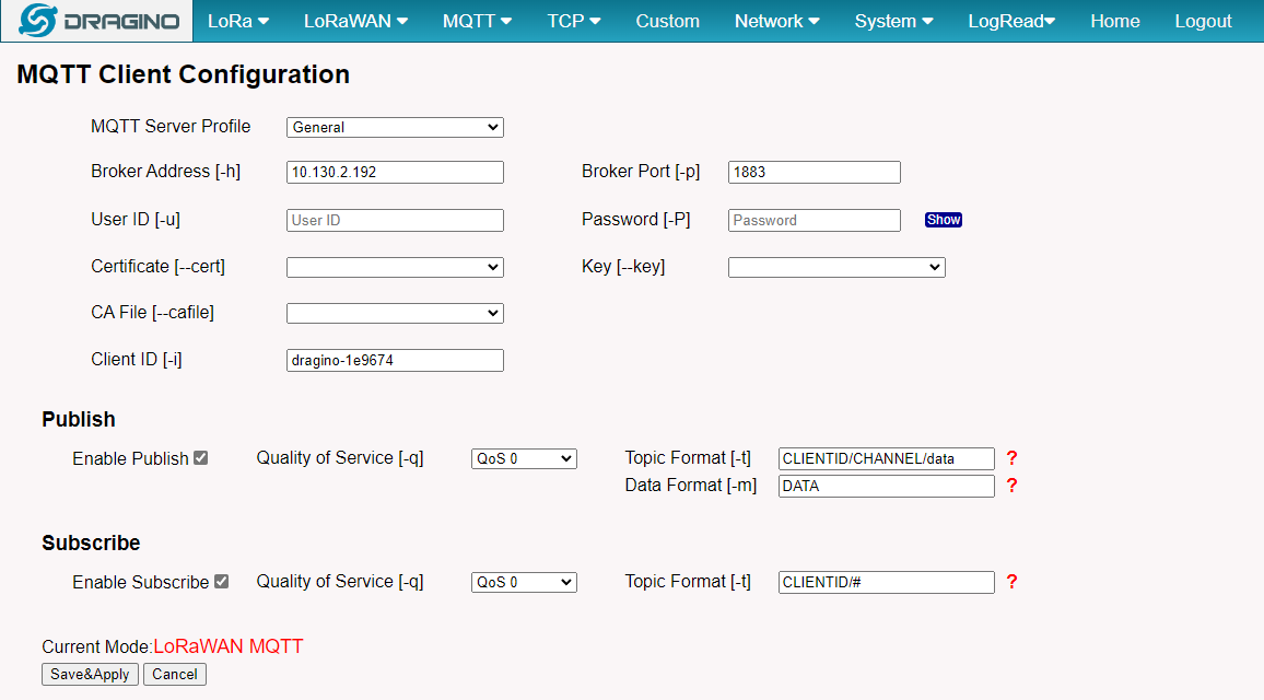
Step 3: Set up publish format and MQTT channel. The LG308 will store the Data from End node in HEX format in the file.
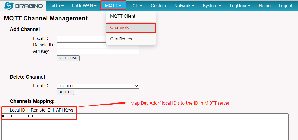
Step 4: Map the Device Address to Remote ID in MQTT server.
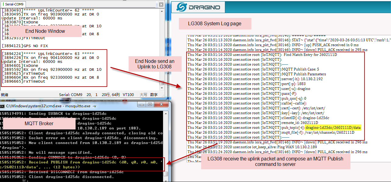
Step 5: Upstream: Save the change, we can see the log info via "sytem log", End Node and MQTT Server
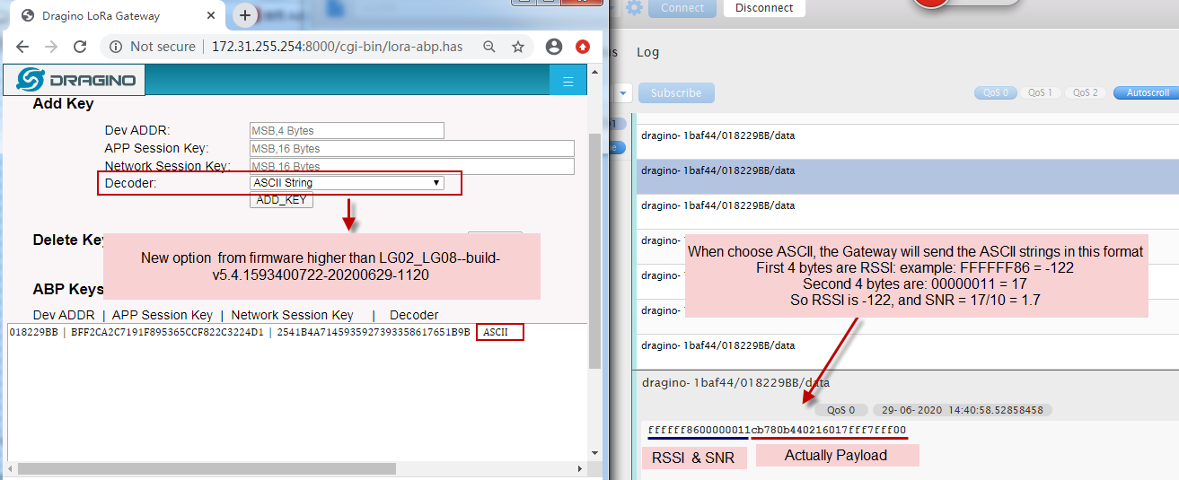
Choose ASCII Format
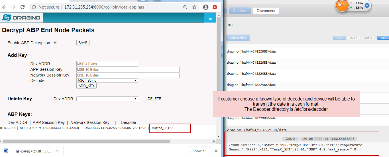
LHT65 Decoder
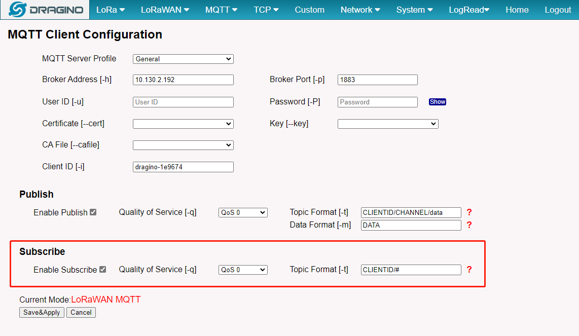
Step 6: Set up subscribe ** : Subscribe a topci for downstream.
Step 7: Downstream: Save the change, we can see the log info via "sytem log", End Node and MQTT Server.
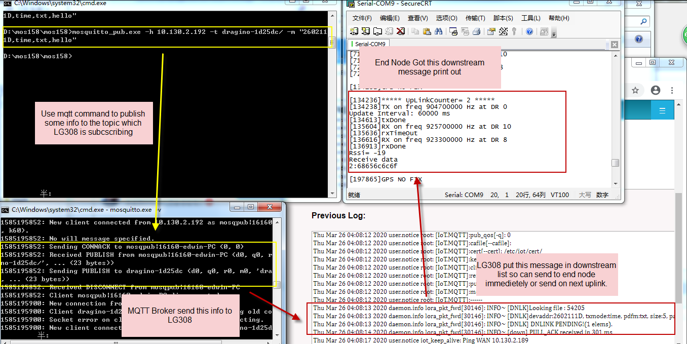
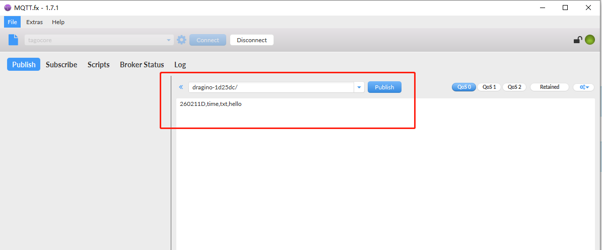
mosquitto_pub -h $server_address -p $server_port -t $Client_ID -m "dev_addr,imme/time,txt/hex,payload"
mosquitto_pub -h 10.130.2.192 -p 1883 -t dragino-1d25dc/ -m "260211D,time,txt,hello"
mosquitto_pub -h $server_address -p $server_port -t $Client_ID -m "dev_addr,imme/time,txt/hex,payload,txpw,txbw,SF,frequency,rxwindow"
mosquitto_pub -h 10.130.2.192 -p 1883 -t dragino-1d25dc/ -m "260211D,time,txt,hello,20,1,SF12,923300000,2" Notice: The text use for Downstream must meet the requirement from LG308 Downstream Payload
Or use MQTT.fx
3.3 Use LoRaWAN Protocol for communication -- For LPS8V2
The LPS8v2 gateway features a built-in ChirpStack LoRaWAN server and an MQTT Forwarder. This function allows the gateway to act as a bridge, seamlessly forwarding data from your LoRaWAN end nodes to a specified MQTT broker (either local or cloud-based). It can also receive downlink commands from the MQTT broker and send them back to the end devices.
This section provides a step-by-step guide to configure this feature.
3.3.1 Register End Devices and Gateway
Refer Register Node to Chirpstack and **Register Gateway to Chirpstack**to know How do register node devices and gateways to the built-in chirpstack server
3.3.2 Verify Sensor Data on the Built-in Server
Before configuring the MQTT forwarder, it's highly recommended to confirm that the built-in ChirpStack server is successfully receiving data from your node. This helps isolate whether future issues originate from the LoRa communication link or the MQTT forwarding step.
- Log in to the LPS8v2's built-in ChirpStack Web interface (typically accessible at http://[Gateway-IP]:8080).
- Navigate to Applications -> [Your Application] -> Devices -> Click on your end device.
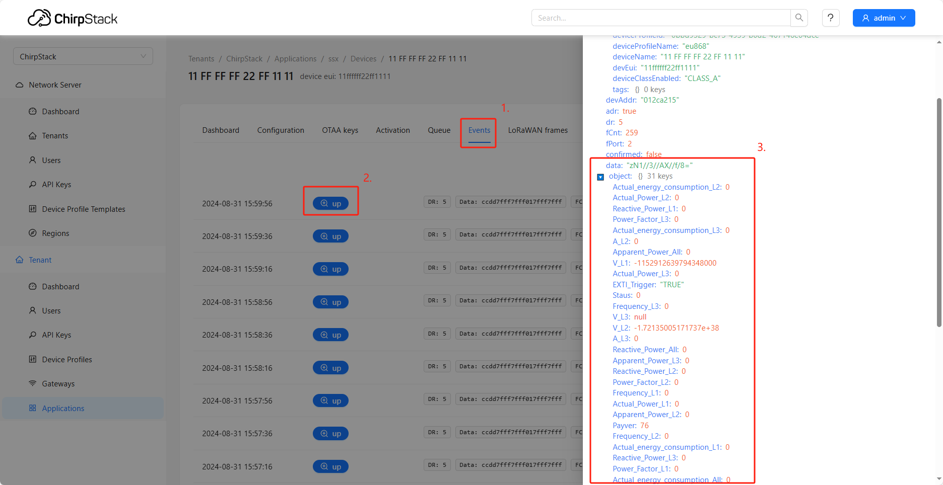
- Click on the Events tab.
- In the event list, you should see uplink events. Click the corresponding +up link to expand and view the detailed JSON data payload. If data appears here, your LoRaWAN communication link is functioning correctly.
3.3.3 Configure the MQTT Forwarder (Uplink)
Next, configure the MQTT forwarding settings in the LPS8v2's main web administration panel.
-
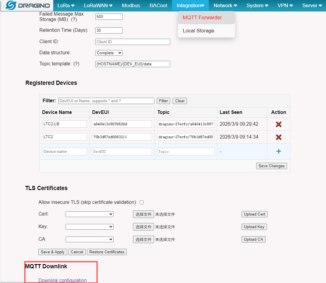
Go to the Integration -> MQTT Forwarder page.
-
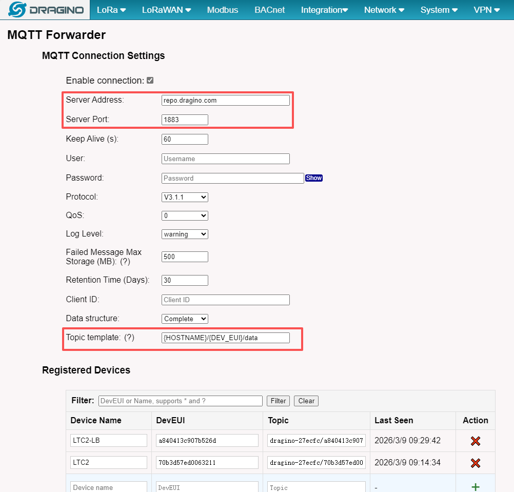
In the upper section labeled MQTT Forwarder, configure the following:
-
Server Address: Enter the IP address or domain name of your MQTT broker.
-
Server Port: Enter the port of your MQTT broker (default is 1883).
-
Topic template: Use placeholder variables to define the MQTT topic where uplink messages will be published. You can combine text and variables, for example:
- {HOSTNAME}: Gateway hostname. Current: dragino-27ecfc
- {GWID}: Gateway ID (GWID). Current: a84041fdfe27ecfc
- {DEV_EUI}: Device DevEUI.
- {DEVICE_NAME}: Device name (if known).
-
-
After entering the details, click Save & Apply.
- Example: If your gateway hostname is dragino-27ecfc, the device's DevEUI is a840413c907b526d, and you use the template {HOSTNAME}/{DEV_EUI}/data, uplink data will be published to the topic dragino-27ecfc/a840413c907b526d/data.
3.3.4 Verify MQTT Uplink Result
Once configured, you can test the uplink path.
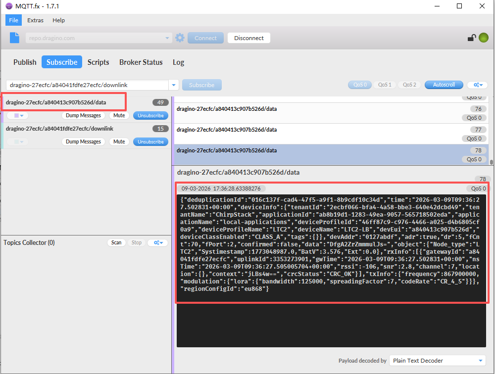
- Use an MQTT client tool (such as mosquitto_sub or MQTT.fx) to connect to your MQTT broker.
- Subscribe to the topic you configured in step 3.3.3 (e.g., dragino-27ecfc/a840413c907b526d/data).
- Trigger your end device to send a new data packet.
- You should see the sensor data, typically in a JSON format, appear in your MQTT client, confirming successful forwarding.
3.3.5 Configure MQTT Downlink
The LPS8v2 can receive downlink commands via MQTT. This feature works by calling the built-in ChirpStack API.
-
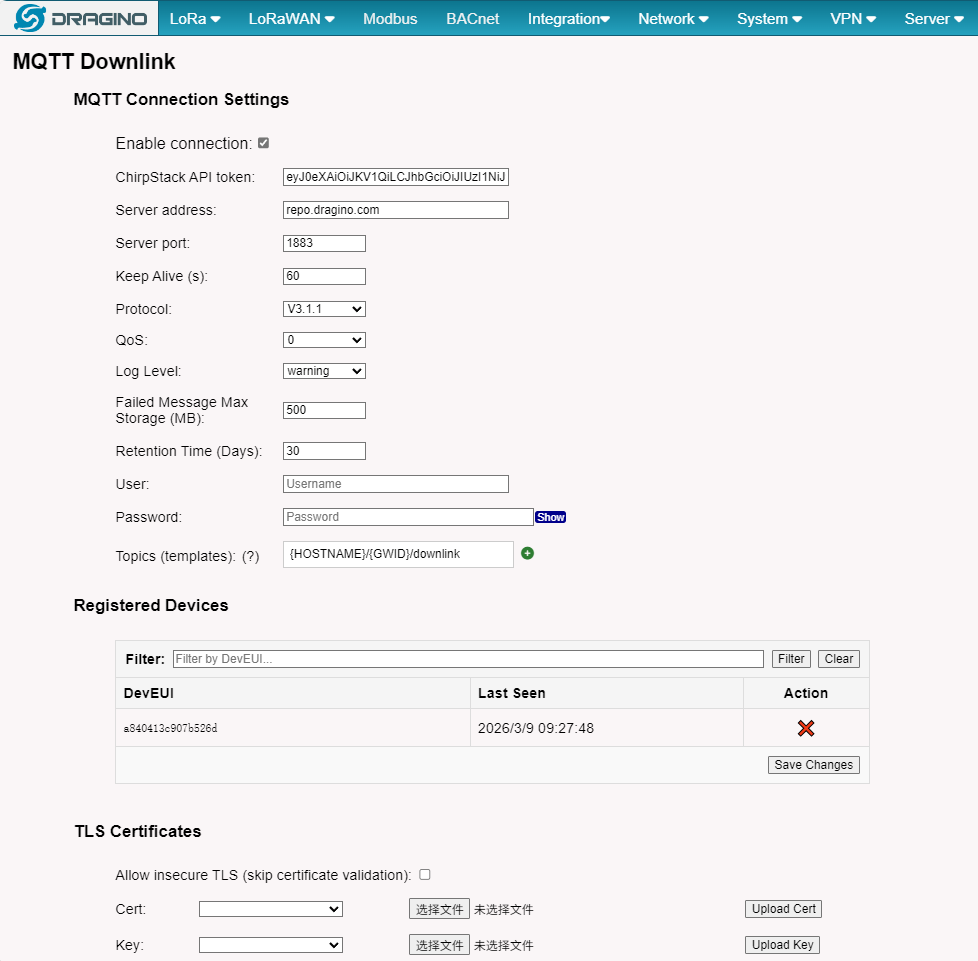
On the same Integration -> MQTT Forwarder page, locate the MQTT Downlink section at the bottom left.
-
ChirpStack API token:
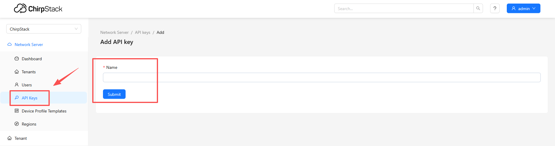
- Open a new browser tab and log in to the built-in ChirpStack Web interface (port 8080).
- Go to API Keys. Click Create API Key.
- Give the key a name (e.g., "mqtt-downlink"). You can generally leave the default permissions or adjust as needed. Click Submit.
- Important: Immediately copy the generated API token from the pop-up dialog and save it securely. You cannot view it again after closing the dialog.
- Paste this copied token into the ChirpStack API token field back on the LPS8v2's MQTT configuration page.
-
Enter the same Server Address and Server Port for your MQTT broker.
-
Click Save & Apply.
3.3.6 Send an MQTT Downlink Command
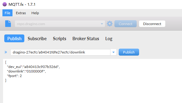
Now you can send downlink commands to your end device by publishing a specifically formatted message to your MQTT broker.
Publish Topic: {HOSTNAME}/{GWID}/downlink
- {HOSTNAME}: Gateway hostname (current: dragino-27ecfc)
- {GWID}: Gateway ID without colons (current: a84041fdfe27ecfc)
- {DEV_EUI}: Device DevEUI (used when matching wildcard topics)
Downlink Message Format:
{
"dev_eui":"a840413c907b526d",
"downlink":"0100000F",
"fport": 2
}
- dev_eui: The DevEUI of the target end device.
- downlink: The payload data you wish to send, formatted as a hexadecimal string.
- fport: The FPort to use for the downlink (valid range: 1-223).
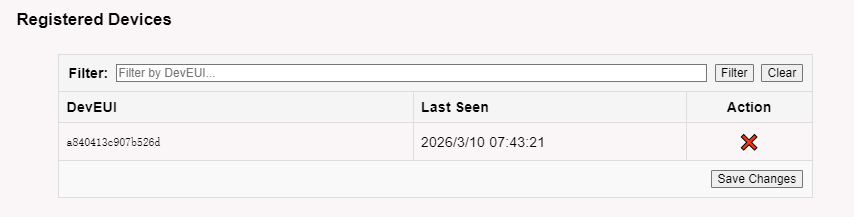
Check the MQTT Downlink Page
On the LPS8v2's MQTT Downlink page will first be in the downlink state
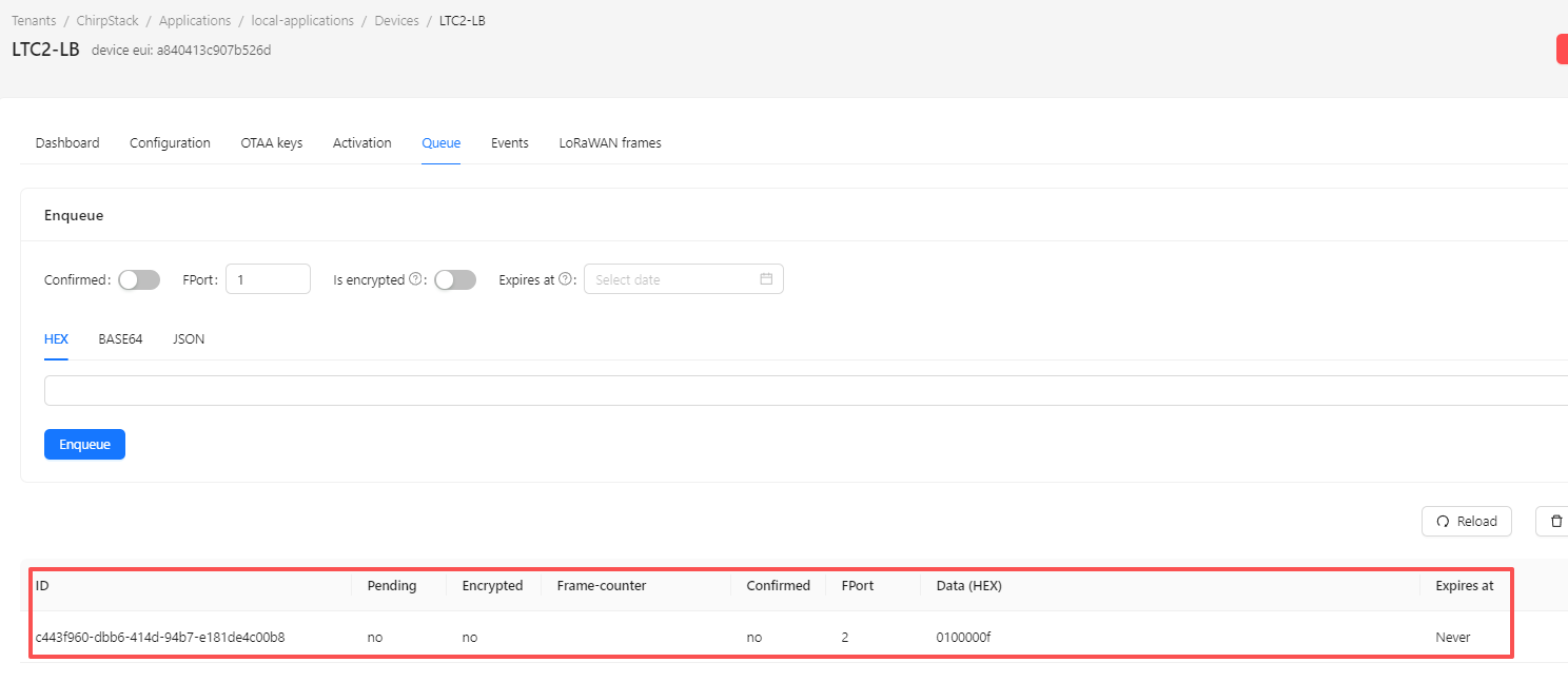
Check the ChirpStack Queue
4. How to ask for Support
If a user still not have trouble making it works. please send a mail to support@dragino.com with the below info:
- Detail of your LoRaWAN end node.
- Gateway Model and firmware version
- A set of screenshots you configure in the gateway according to our instruction
- A full log of "logread -f"
0
Toggle the left panel column.