UART/TTL Firmware Update
1. LoRaST v4 base Hardware
Below hardware use LoRaST v4 module. They supports UART Access for AT Command and Firmware Upgrade.
Models
Mother Board
UART for AT Commands
UART for Upgrade Firmware
PS-LB, PS-LB-NA, SDI12-LB
SIB
Instruction
Instruction
SN50v3, S31-LB, S31B-LB,D20-LB.D20S-LB, D21-LB, D22-LB , SW3L-LB
SN50v3
Instruction
Instruction
LHT65N
LHT65N
RS485-LB, SE01-LB, SPH01-LB,
LMS01-LB, LDS12-LB, LDS40-LB,
DDS75-LB, DDS45-LB, DDS04-LB,
DDS20-LB, MDS120-LB, MDS200-LB, WSC2-LB, LDS25-LB
RS485-BL
Instruction
Instruction
2. UART for AT Commands
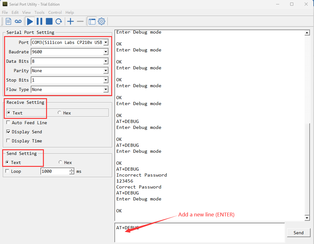
2.1 General software set up for AT Commands via UART
-
Use a general serial tool.
-
Connect PC to device's UART interface
-
Set up serial tool with : BaudRate: 9600, databit:8, No parity, No flow control.
-
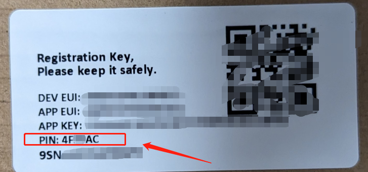
The password is the last six characters of APPSKEY or PIN of box
Example:
APPSKEY= 41 85 71 A7 5D 7E 54 52 25 58 74 85 96 14 74 85
The password:147485
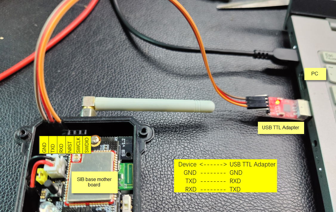
2.2 UART Connection for SIB mother board
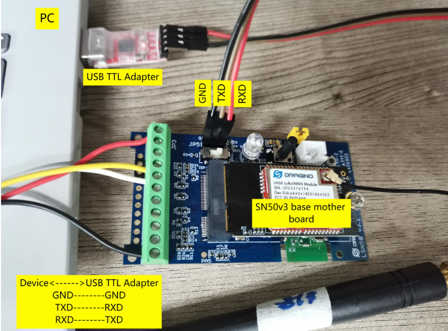
2.3 UART Connection for SN50v3 base mother board
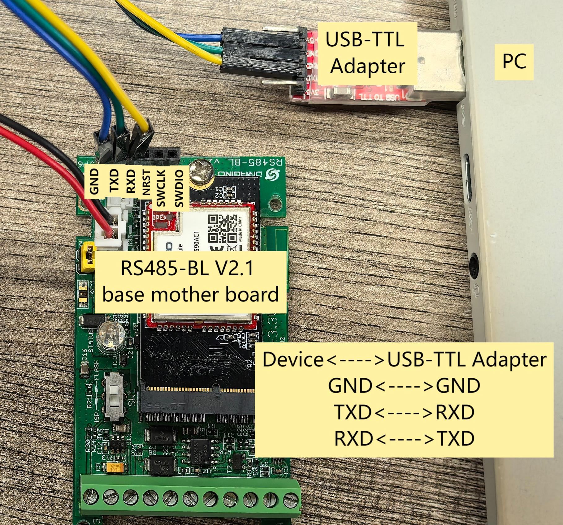
2.4 UART Connection for RS485-BL V2.1 base mother board
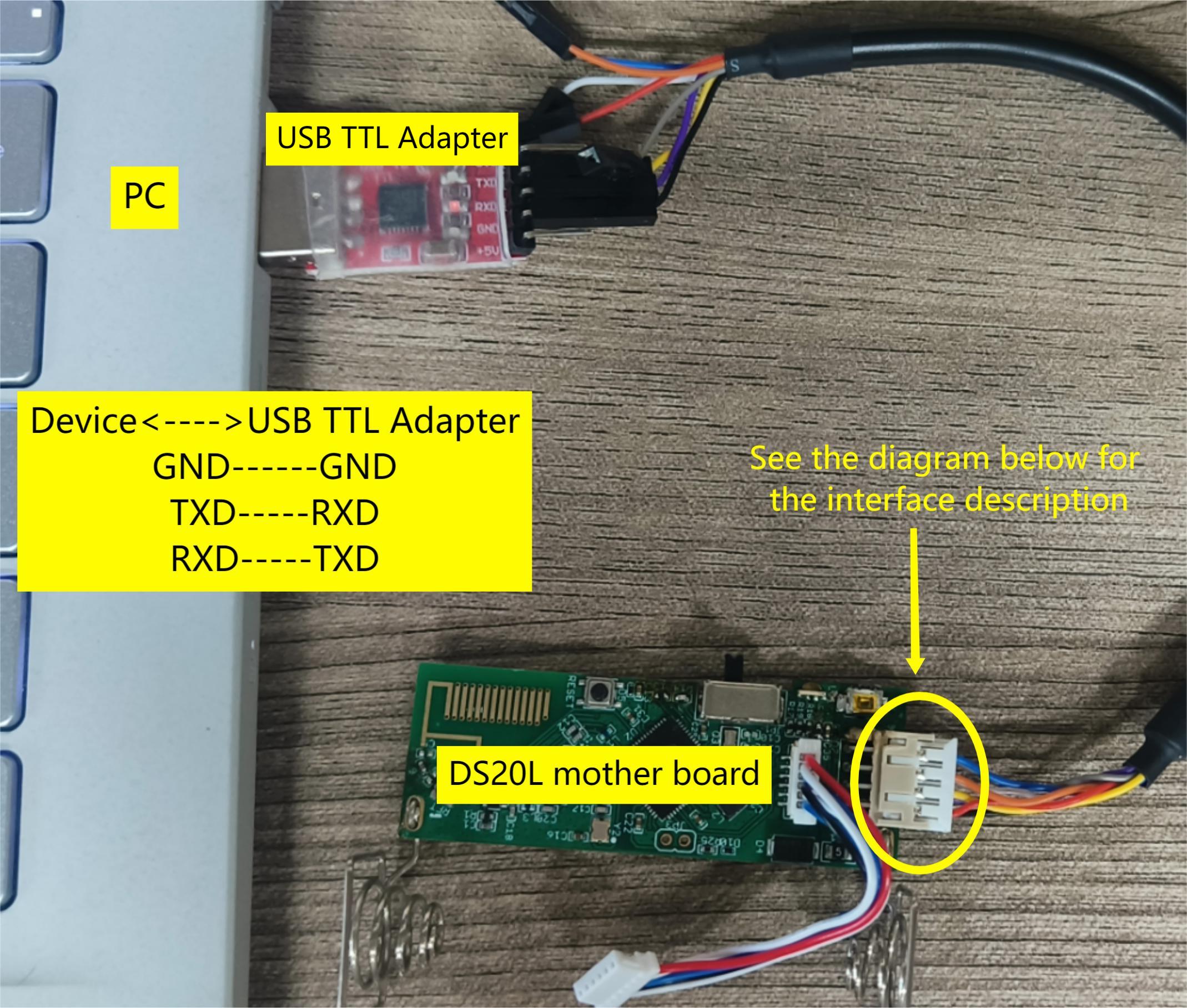
2.5 UART Connection for DS20L mother board
UART Connection for DS20L mother board:
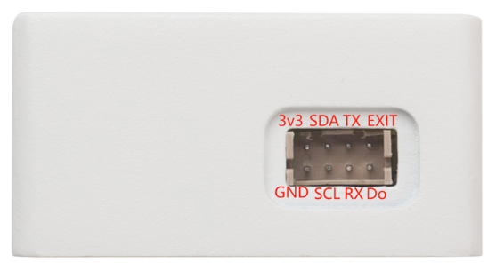
Interface definition:
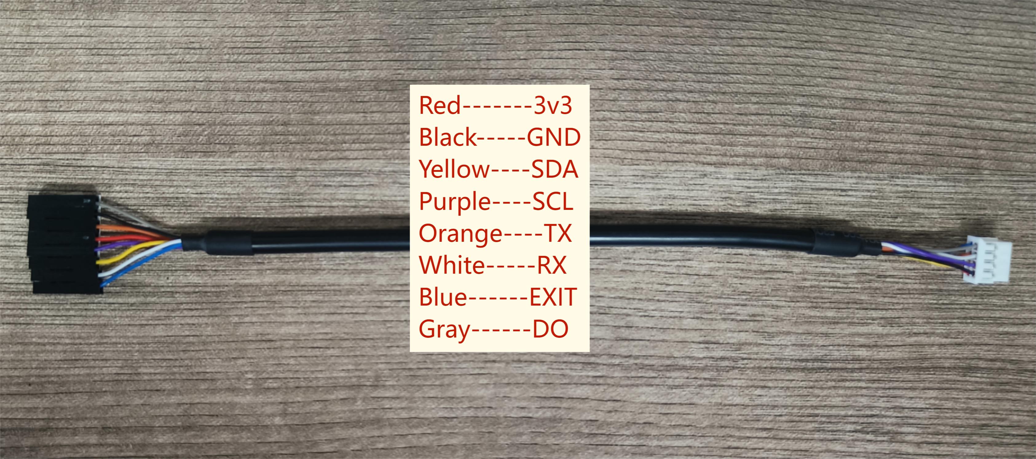
DS20L programming line:
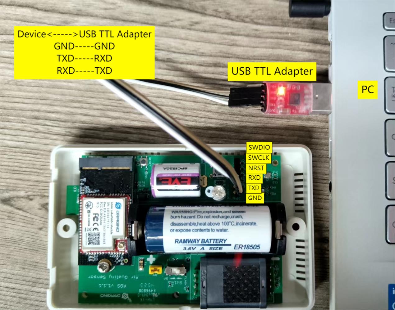
2.6 UART Connection for AQS01-L mother board
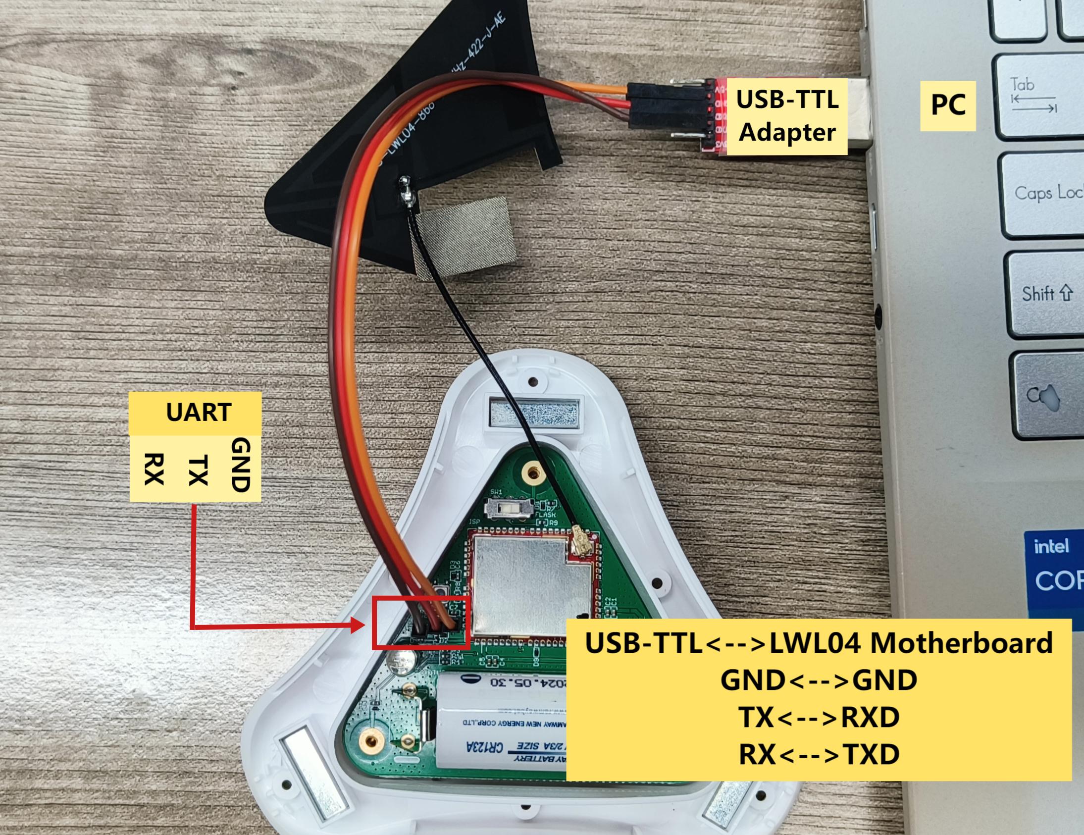
2.7 UART Connection for LWL04 mother board
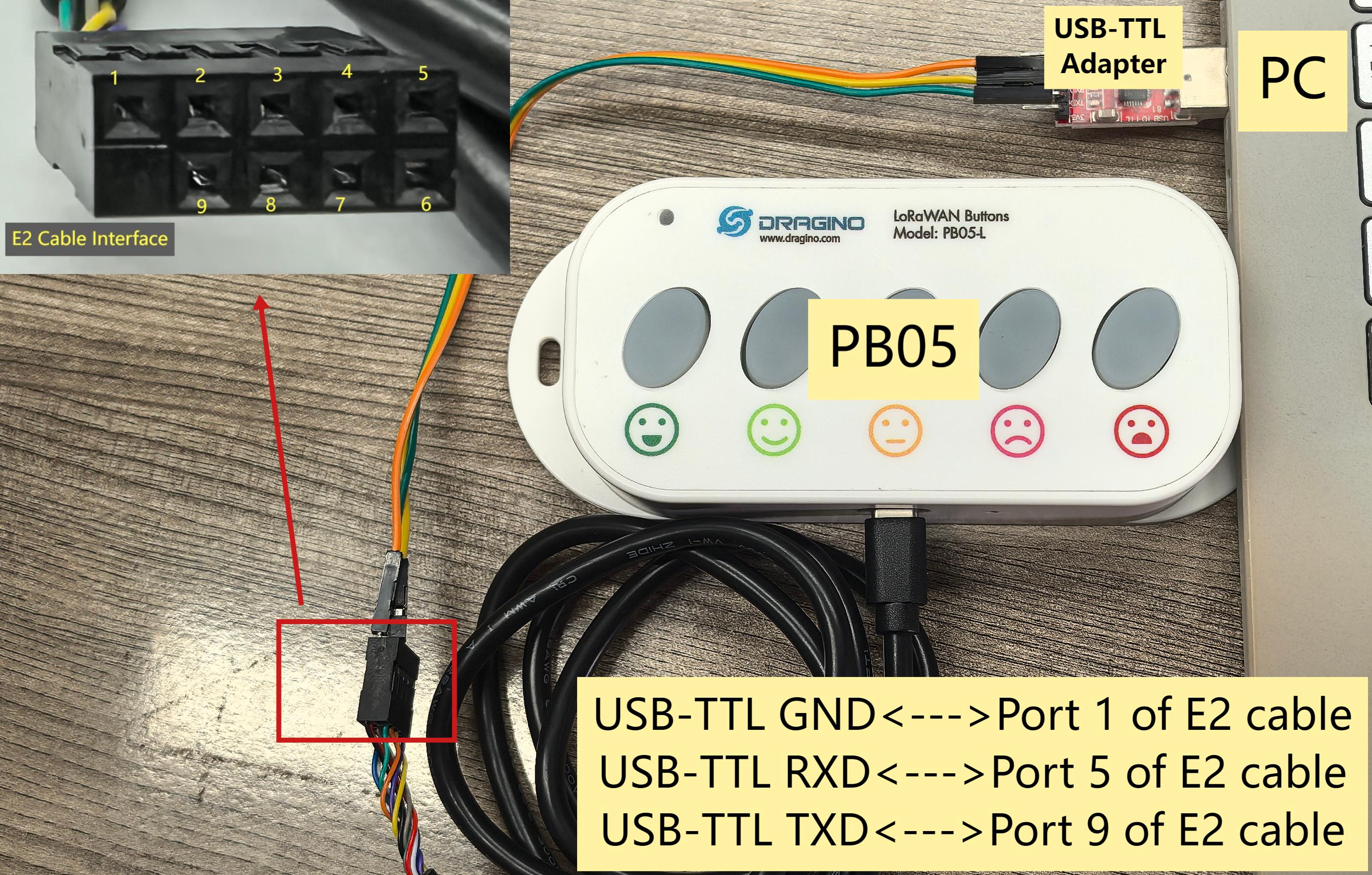
2.8 UART Connection for PB05 mother board
- If you use Dragino Sensor Manager Utility.exe to upgrade the PB05 firmware, connect as follows:
- To use TremoProgrammer to burn firmware, the PB05 must be in burn mode, i.e. the USB-TTL adapter 3.3V must be connected to the BOOT_CONTROL pin of the PB05.
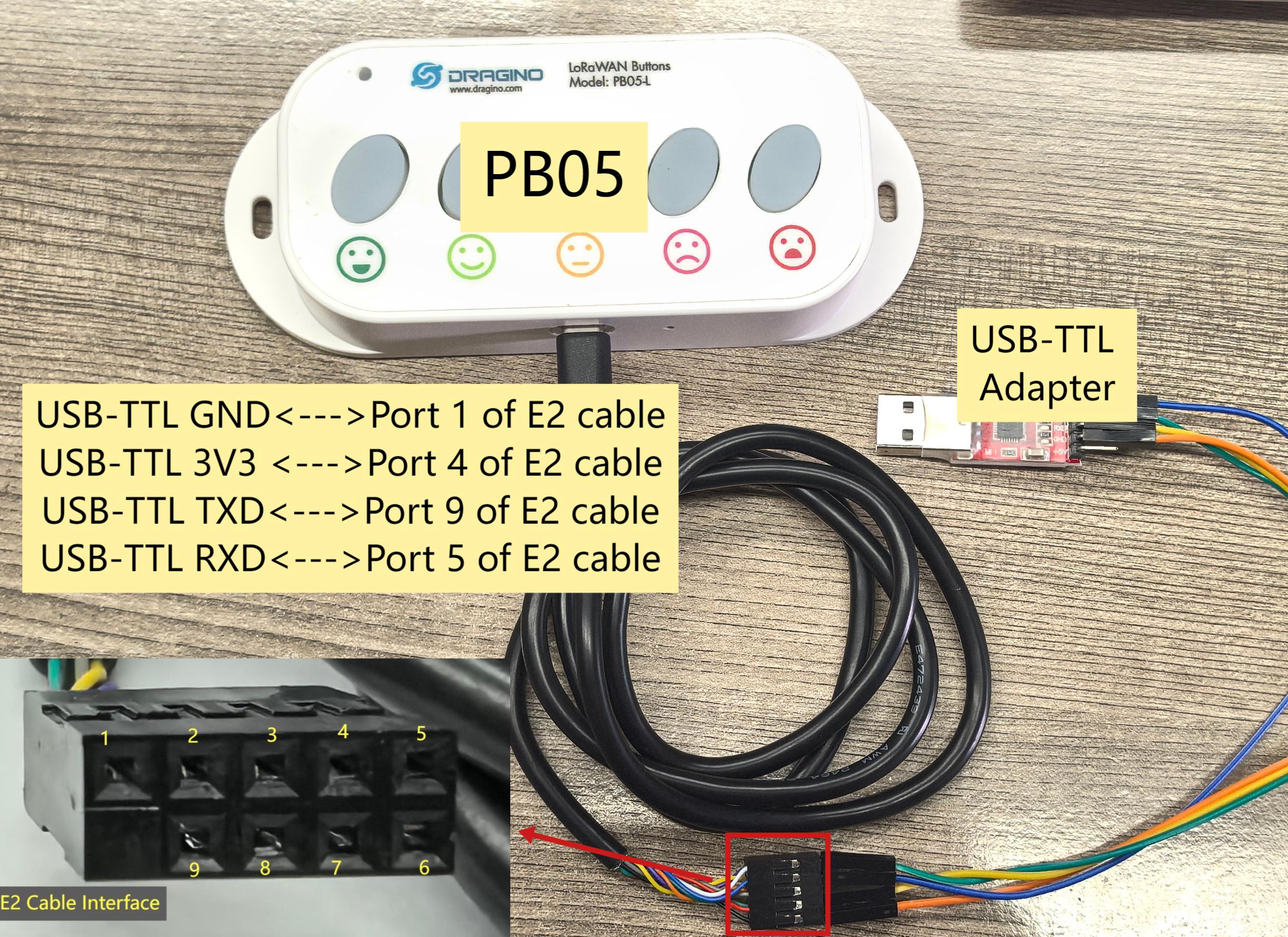
Note: 1. How to enter burn mode
Connect the PB05, E2 cable and USB-TTL adapter according to the above wiring diagram, and then press the ACT button to reactivate the PB05 (or directly install the battery again). After this operation, the PB05 will enter the burn mode.
2.How to exit burn mode
After the firmware update is complete, remove any wiring, then reinstall the battery, and the PB05 will exit burn mode and restart.
3. UART for Firmware Upgrade
3.1 Check Your device already have bootloader
3.1.1 What is Dragino Bootloader?
Dragino Bootloader is a customizer made bootloader which support below features:
- OTA Update via LoRa
- OTA Batch update configure via LoRa
All Dragino End Devices base on LoRa ST v4 supports Dragino Bootloader.
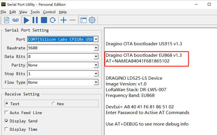
3.1.2 How can i know if my device already have bootloader?
If a device has a bootloader. it will output bootloader info to UART when boot. As below:
3.1.3 How to upload bootloader to device?
If your is LoRa ST v4 base hardware and doesn't have bootloader. You can upload a bootloader to it.
Downlink Link for OTA bootloader. Update a firmware via TremoProgrammer:
LoRaSTv4 Base hardware support UART update firmware. the UART connection is the same as AT Command connection, with the need for two extra action. See below for the steps:
**Step1**: Set BOOT Switch to **ISP** mode. ISP mode is for update firmware specially.
**Step2**: Press **Reset** button, the module will then boot into program mode.
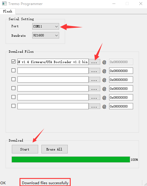
**Step3**: Click "Start", use **TremoProgrammer** to update the firmware to LoRaST v4.
**Step4**: Set BOOT Switch to **FLASH** position. Press Reset button again and module will run the new software.
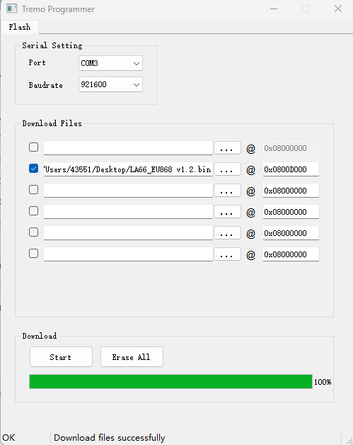
Below is the method for how to update via TremoProgrammer:
-
TremoProgrammer download link: https://www.dropbox.com/sh/j0qyc7a9ejit7jk/AACtx2tK4gEv6YFXMIVUM4dLa?dl=0
-
Run TremoProgrammer.
-
Choose software and set the address to 0x08000000.
-
Rember to set BOOT Switch to FLASH after update finish. And you should be about to see Bootloader info in output after update
3.2 Update Firmware (Assume the device already have a bootloader)
Video Instruction: https://youtu.be/G_xEZnNjJmM
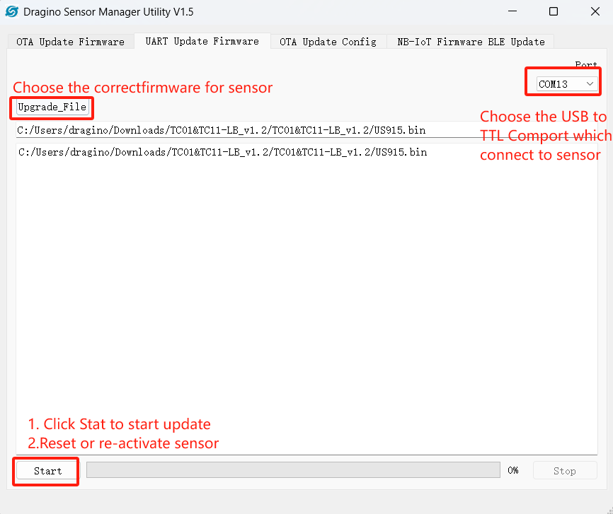
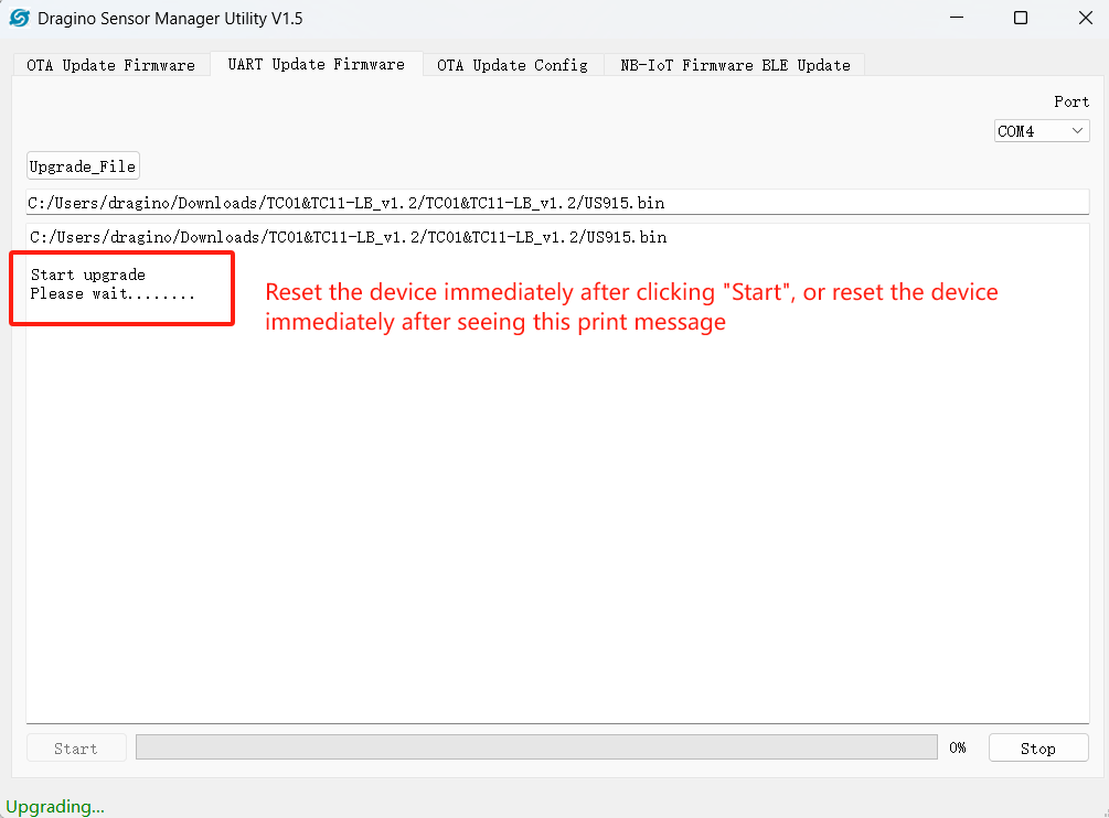
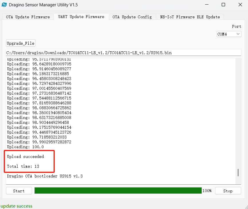
3.2.1 Update a firmware via Dragino Sensor Manager Utility.exe
-
Download OTA Tool
-
Set the switch to Flash
-
Use below schedule to update:
4. FAQ
4.1 How to recover if upgrade wrong file to bootloader?
You can just upload the bootloader again.
4.2 How to recover if upgrade wrong firmware via Dragino Sensor Manager Utility.exe?
The UART upgrade via Dragino Sensor Manager Utility.exe is base on Dragino Bootloader. So if you are able to upgrade some file via this tool. It means the device has bootloder.
The upgrade via Dragino Sensor Manager Utility is base on firmware level and won't effect the bootloader. If you upgrade a wrong firmware file, you can try below:
-
UART upgrade via Dragino Sensor Manager Utility again to the correct version. The password should use the AT PIN for the wrong firmware. (This method is not 100% work, depends which wrong firmware you have upgraded)
-
Use TremoProgrammer to update firmware. Insturction
-
Use OTA update, this is base on Bootloader so it will work. Make you choose the correct frequency band (base on the firmware version in the sensor or use EU868 which is the default setting.)
4.3 How to use TremoProgrammer to update firmware if there is bootloader in the device?
Make sure your device already bootloader while use this update. Otherwise device won't be able to boot ( can be solve by upload a bootloader to the device).
LoRaSTv4 Base hardware support UART update firmware. the UART connection is the same as AT Command connection, with the need for two extra action. See below for the steps:
 **Step1**: Set BOOT Switch to **PROG** mode. PROG mode is for update firmware specially.

 **Step2**: Press **Reset** button, the module will then boot into program mode.

 **Step3**: Use **TremoProgrammer** to update the firmware to LoRaST v4.

 **Step4**: Set BOOT Switch to **FLASH** position. Press Reset button again and module will run the new software.
Below is the method for how to update via TremoProgrammer:
-
Software download link: https://www.dropbox.com/sh/j0qyc7a9ejit7jk/AACtx2tK4gEv6YFXMIVUM4dLa?dl=0
-
Run TremoProgrammer.
-
Choose software and set the address to 0x0800D000. VERY IMPORTANT for this address.
-
Rember to set BOOT Switch to FLASH after update
4.4 How to troubleshoot incorrect password
-
Please use lowercase letters.
-
You need to add line breaks when entering commands.
-
Upgrade the firmware to display password firmware
Upgrade steps:
Instruction
Firmware location:After updating the firmware, run the firmware.
Press the restart button and the password will be printed in the serial port output.
Save the password and re-upgrade the firmware to the original firmware.Note: When upgrading to the original firmware, you need to add the Bootloader firmware.
Bootloader Firmware location(Please use V1.3):
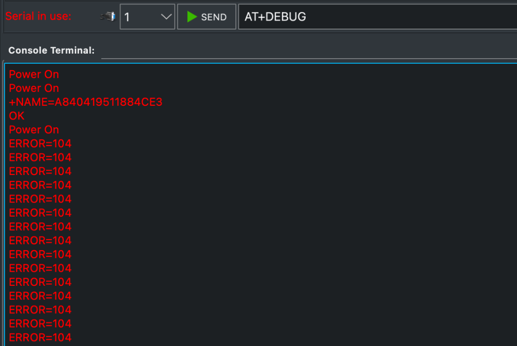
4.5 Why does the serial Assistant print ERROR: 104/ERROR=104? How to Restore UART/AT Command Communication?
Symptoms:
No output on the serial terminal when the device powers on.
AT commands return ERROR=104 or no response at all.
The device is communicating with the network, but the UART is unresponsive.
ERROR: 104/ERROR=104 usually indicates that there is a problem when communicating with a sensor via a USB-TTL device. This error can be due to a variety of reasons, such as communication parameter setting errors, hardware connection problems, etc.
Follow these steps to restore the AT command interface.
Step 1: Check Hardware Connections
Ensure your USB-to-TTL serial converter is correctly wired to the PS-LB-NA's UART pins:
- Device TX pin must connect to Converter RX pin.
- Device RX pin must connect to Converter TX pin.
- GND pins must be connected together.
- Check that all connections are secure and not loose.
Refer to Section 2 of this manual to correctly connect the USB-TTL to the device motherboard and set the communication parameters correctly.
Step 2: Verify Serial Port Settings
Configure your terminal software (e.g., PuTTY, Tera Term) with the following settings:
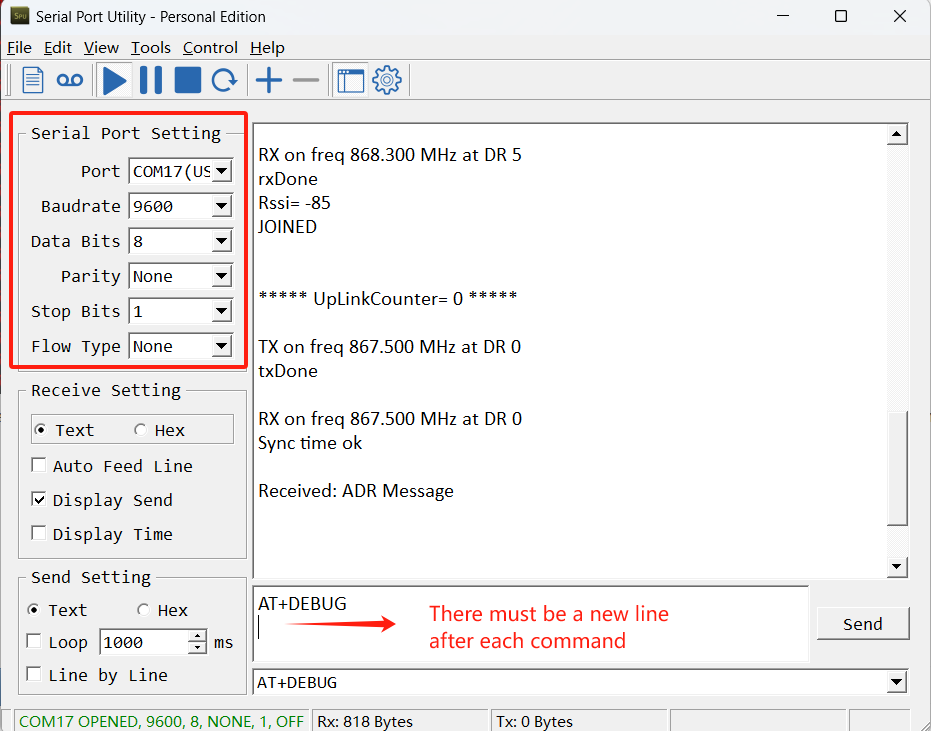
Step 3: Perform a Reset (Key Step)
Power cycle the device (turn it off and back on).
After completing the above steps, press the black reset button on the device motherboard to reset the device.
Step 4:Test the Connection
After the power cycle, your serial terminal should display the Dragino boot-up messages followed by the AT> command prompt. This confirms the UART communication has been restored.
You will now need to reconfigure your device (LoRaWAN keys, sensor settings, etc.) using AT commands.
Step 5:If the Problem Persists:
Try using a different USB-to-TTL converter cable to rule out a hardware fault.
Double-check all pin connections and solder points.