End Device AT Commands and Downlink
1. Introduction
Dragino LoRaWAN End Node support two types of AT Commands and Downlink Commands:
-
Common Commands: They should be available for each sensor, such as: change uplink interval, reset device.
-
Sensor Related Commands: Only for special sensor, such as control relay, poll RS485 device.
This page shows the common commands since Dragino LoRaWAN stack DR-LWS-005. Make sure the end node support stack higher than DR-LWS-005 before checking this page.
2. How to use AT Commands or Downlink command
-
AT Command : See Devices User Manual for how to connect to device via USB TTL adapter and use. The user manual can be found in each product page of Dragino Products User Manual.
-
LoRaWAN Downlink Command: The gateway transfer downlink command in HEX format. This page shows the Downlink Command In HEX format. Please note some LoRaWAN servers use base64 as downlink code so user need to convert HEX to Base64 and use. Below are references for how to use downlink command: ** Use HEX format to send a downlink: TTN v3 ** Use Base64 format to send a downlink: Chirpstack, How to Convert? ** See use note for more serves Servers Note(IoT LoRaWAN Server)
3. Support End Node and firmware version
Dragino STM32 base hardware Firmware / LoRaWAN stack list
|Model|Description|Firmware Version <--> Stack Version
|
LSN50-v1, LSN50-V2,
|
Open Source Generic LoRaWAN Sensor Node
|
(((
LSN50 v1.6.0 <--> DR-LWS-003;
(((
LSN50 v1.7.0 <--> DR-LWS-005; --> Support since this version
)))
)))
|
LGT92,
|
LoRaWAN GPS Tracker
|
(((
LGT92 v1.6.3 <--> DR-LWS-003;
(((
LGT92 v1.6.4 <--> DR-LWS-005;--> Support since this version
)))
)))
|
LBT1,
|
LoRaWAN BLE Indoor Tracker
|
LBT1 v1.0 <--> DR-LWS-005;
|
RS485-LN,
|
LoRaWAN RS485 Modbus Converter
|
RS485-LN v1.3 <--> DR-LWS-005;
|
LHT65,
|
LoRaWAN Temperature & Humidity Sensor
|
(((
LHT65 v1.7 <--> DR-LWS-003;
(((
LHT65 v1.8.0 <--> DR-LWS-005;--> Support since this version
))) )))
4. System Management Commands
4.1 Change Uplink Interval
Feature: Change LoRaWAN End Node Transmit Interval.
AT Command: AT+TDC
|Command Example|Function|Response |AT+TDC=?|Show current transmit Interval|30000 OK
the interval is 30000ms = 30s
|AT+TDC=60000|Set Transmit Interval|OK Set transmit interval to 60000ms = 60 seconds
Downlink Command: 0x01
Format: Command Code (0x01) followed by 3 bytes time value.
If the downlink payload=0100003C, it means set the END Node's Transmit Interval to 0x00003C=60(S), while type code is 01.
-
Example 1: Downlink Payload:** 0100001E**
// Set Transmit Interval (TDC) = 30 seconds -
Example 2: Downlink Payload:** 0100003C**
// Set Transmit Interval (TDC) = 60 seconds
4.2 Reboot End Node
Feature: Reboot End Node to perform a new OTAA or ABP Join.
**AT Command: ATZ // **Trig a reset of the MCU
|Command Example|Function|Response |ATZ|Reset MCU| Device reset and show booting info
LSN50 Device/LoRa ST Module
Image Version: XX
Frequency Band: XX
DevEui= XX XX XX XX XX XX XX XX
Downlink Command: 0x04
Format: Command Code (0x04) followed by FF.
If the downlink payload=04FF, the end node will reboot.
4.3 Reset to factory Default
Feature: Reset the parameters to Factory Default, factory default value depends on the firmware settings, the OTAA and ABP keys will reserve after this command.
**AT Command: AT+FDR // **Reset to factory default
|Command Example|Function|Response |AT+FDR|Reset to factory default| Device reset to factory default parameters and show booting info
LSN50 Device/LoRa ST Module
Image Version: XX
Frequency Band: XX
DevEui= XX XX XX XX XX XX XX XX
Please set the parameters or reset Device to apply change
Downlink Command: 0x04
Format: Command Code (0x04) followed by FE.
If the downlink payload=04FE, Reset Parameters to Factory Default, Keys Reserve.
4.4 Show Firmware Version
Feature: Show firmware version. No downlink command yet.
**AT Command: AT+VER // **Image Version and Frequency Band
|Command Example|Function|Response |AT+VER=?|Show Image version and Frequency Band| 1.3 EU868
OK
Downlink Command: 0x26 (Valid in 006 stack)
Format: Command Code (0x26) followed by 1 byte.
If the downlink payload=**2601, **Device will reply with firmware version info, device info. frequency band info. detail please check device user manual. Total 5 bytes Example: If device is of firmware version 1.1.0 Upload: xx -- yy -- zz -- 110 total 5 bytes( FPort= 5 usually).
xx: Software Type:
- 0x00 01: LGT92 Version
- 0x00 02: LBT1
- 0x00 03: LSE01/LDDS75/LDDS20/LSPH01/LLMS01/LSNPK01
yy: Frequency Band:
- 0x01: EU868
- 0x02: US915
- 0x03: IN865
- 0x04: AU915
- 0x05: KZ865
- 0x06: RU864
- 0x07: AS923
- 0x08: AS923-2
- 0x09: AS923-3
- 0xa0: AS923-4
zz: Subband
firmware version: v1.1.0 --> 110
4.5 Show System Configure
Feature: Show All configure. No downlink command yet.
**AT Command: AT+CFG // **Print all configurations
|Command Example|Function|Response |AT+CFG|Show all configures| AT+DEUI = XX XX XX XX XX XX XX XX AT+DADDR=XXXXXXXX ………. AT+RX2WTO=X AT+CHS=868100000 OK
4.6 Set time synchronization method(The network server must support LoRaWAN v1.0.3)
Feature: Set the system time synchronization.
AT Command: AT+SYNCMOD
|Command Example|Function|Response |AT+SYNCMOD=?|Get the current time synchronization configuration| 1 (Default)
((( OK
))) |AT+SYNCMOD=0|Disenable system time synchronization.|OK |AT+SYNCMOD=1|Enable system time synchronization.|OK
**Downlink Command: 0x28 **
Format: Command Code (0x28) followed by 1 byte.
- Example 1: 28 00
//Equal to AT+SYNCMOD=0 - Example 2: 28 01
//Equal to AT+SYNCMOD=1
Note: This command takes effect after the node is reset, or after downlink 0x2601(query device status).
5. Keys, IDs and EUIs management
5.1 Application EUI
Feature: Get or Set the Application EUI.
AT Command: AT+APPEUI
|Command Example|Function|Response |AT+APPEUI=?|Get the Application EUI|00 b3 d5 00 00 00 00 00 OK
|AT+APPEUI=00 b3 d5 7e f0 00 4d 34|Set the Application EUI|OK
5.2 Application Key
Feature: Get or Set the Application Key.
AT Command: AT+APPKEY
|Command Example|Function|Response |AT+APPKEY=?|Get the Application Key|00 35 55 55 22 23 55 53 43 24 23 42 34 35 35 35 OK
|AT+APPKEY=00 35 55 55 22 23 55 53 43 24 23 42 34 35 35 35|Set the Application Key|OK
5.3 Application Session Key
Feature: Get or Set the Application Session Key.
AT Command: AT+APPSKEY
|Command Example|Function|Response |AT+APPSKEY=?|Get the Application Session Key|00 7d dc 73 33 d3 eb 9e 14 38 d5 a4 3e 62 5b e2 OK
|AT+APPSKEY=00 7d dc 73 33 d3 eb 9e 14 38 d5 a4 3e 62 5b e2|Set the Application Session Key|(While Error in format, return AT_PARAM_ERROR) OK
5.4 Device Address
Feature: Get or Set the Device Address.
AT Command: AT+DADDR
|Command Example|Function|Response |AT+DADDR=?|Get the Application Session Key.|(While Error in format, return AT_PARAM_ERROR) A8 40 41 FF
OK
|AT+DADDR=A8 40 41 FF|Set the Application Session Key.|OK
5.5 Device EUI
Feature: Get or Set the Device EUI.
AT Command: AT+DEUI
|Command Example|Function|Response |AT+DEUI=?|Get the Device EUI.|00 44 34 22 33 45 55 55 OK
|AT+DEUI=A8 40 41 FF FF 12 34 56|Set the Device EUI.|(System will write new value to Device EUI,While Error in format, return AT_PARAM_ERROR) OK
5.6 Network ID
Feature: Get or Set the Network ID.(You can enter this command change only after successful network connection)
AT Command: AT+NWKID
|Command Example|Function|Response |AT+NWKID=?|Get the Network ID.|a8 40 41 ff OK
|AT+NWKID=A8 40 41 FF|Set the Network ID.|OK
5.7 Network Session Key
Feature: Get or Set the Network Session Key
AT Command: AT+NWKSKEY
|Command Example|Function|Response |AT+NWKSKEY=?|Get the Network Session Key.|00 4f 19 25 52 ce 97 09 d7 fa 84 71 db 51 02 92 OK
|AT+NWKSKEY=A8 40 41 FF FF 12 34 56 00 01 02 04 05 06 06 07|Set the Network Session Key.|OK
6. Joining and sending date on LoRaWAN network
6.1 Confirm Mode
6.1.1 AT+CFM command before DR-LWS007 software stack
Feature: Get or Set the confirmation mode (0-1).
AT Command: AT+CFM
|Command Example|Function|Response |AT+CFM=?|Get the confirmation mode|0 OK
|AT+CFM=1|Set the confirmation mode|OK |AT+CFM=2|Set the confirmation mode|While Error in format, return AT_PARAM_ERROR
Downlink Command: 0x05
Format: Command Code (0x05) followed by 1 byte mode value.
If the downlink payload=0501, it means set end node to use confirm mode, while type code is 05.
-
Example 1: Downlink Payload: 0501
// Set AT+CFM=1 -
Example 2: Downlink Payload: 0500
// Set AT+CFM=0
6.1.2 AT+CFM command since DR-LWS007 software stack
AT Command: AT+CFM
|Command Example|Function|Response | AT+CFM=1,0,0
value1 |confirmed uplink| 1
OK
| AT+CFM=0,?,0
value2 |set max retry , range: 0 ~~ 7| 0~~7
OK
| AT+CFM=0,0,1
value3 |uplink fcnt increase by 1 for each retry| 1
OK
Downlink Command: 0x05
Format: Command Code (0x05) followed by 3 bytes mode value.
If the downlink payload=05010101, it means set end node to use confirm mode, while type code is 05.
-
Example 1: Downlink Payload: 05010101
// Set AT+CFM=1,1,1 -
Example 2: Downlink Payload: 05000700
// Set AT+CFM=0,7,0
6.2 Confirm Status
Feature: Get confirmation status of the last AT+SEND (0-1).
AT Command: AT+CFS
|Command Example|Function|Response |AT+CFS=?|Get confirmation status|0 OK
6.3 Join LoRa® Network
Feature: Join network.
AT Command: AT+JOIN
|Command Example|Function|Response |AT+JOIN ?|Get imformation.|AT+JOIN: Join network OK While Error in format, return AT_BUSY_ERROR
6.4 LoRa® Network Join Mode
Feature: Get or Set the Network Join Mode. (0: ABP, 1: OTAA).
AT Command: AT+NJM
|Command Example|Function|Response |AT+NJM=?|Get the Network Join Mode|1 OK
|AT+NJM=0|Set the Network Join Mode|OK |AT+NJM=2|Set the Network Join Mode|While Error in format, return AT_PARAM_ERROR
Downlink Command: 0x20
Format: Command Code (0x20) followed by 1 bytes mode value.
If the downlink payload=2000, it means set the Network Join Mode, while type code is 20.
-
**Example 1: **Downlink Payload: **2000 **
// Set AT+NJM=0 -
Example 2: Downlink Payload: 2001
// Set AT+NJM=1
6.5 LoRa® Network Join Status
Feature: LoRa® Network Join Status.
AT Command: AT+NJS
|Command Example|Function|Response |AT+NJS=?|Get the join status.|0 OK
6.6 Print Last Received Data in Raw Format
Feature: Print Last Received Data in Raw Formatport:data.
AT Command: AT+RECV
|Command Example|Function|Response |AT+RECV=?|print last received data in raw format.|0: OK
6.7 Print Last Received Data in Binary Format
Feature: Print Last Received Data in Binary Formatport:data.
AT Command: AT+RECVB
|Command Example|Function|Response |AT+RECVB=?|print last received data in binary format (with hexadecimal values).|2: 0010 OK
6.8 Send Text Data(Note: The format of this command of LA66 is subject to the manual)
Feature: Send Text Dataport:data.
AT Command: AT+SEND
|Command Example|Function|Response |AT+SEND=12:hello world|Send text data along with the application port.|OK While Error in format, return AT_BUSY_ERROR/AT_BUSY_ERROR/AT_NO_NETWORK_JOINED
6.9 Send Hexadecimal Data(Note: The format of this command of LA66 is subject to the manual)
Feature: Send hexadecimal data along with the application port.
AT Command: AT+SENDB
|Command Example|Function|Response |AT+SENDB=12:abcdef0123456789|Send hexadecimal data along with the application port.|OK |AT+SENDB=abcdef0123456789|Send hexadecimal data along with the application port.|While Error in format, return AT_PARAM_ERROR AT_BUSY_ERROR/AT_NO_NETWORK_JOINED
7. LoRaWAN network management
7.1 Adaptive Data Rate
Feature: Get or Set the Adaptive Data Rate setting. (0: off, 1: on).
AT Command: AT+ADR
|Command Example|Function|Response |AT+ADR=?|Get the Adaptive Data Rate setting.|1 OK
|AT+ADR=0|Set the Adaptive Data Rate setting.|OK |AT+ADR=2|Set the Adaptive Data Rate setting.|While Error in format, return AT_PARAM_ERROR
Downlink Command: 0x22
If the downlink payload=2201, it means setting the adaptive data rate to 1, while type code is 22.
-
Example 1: Downlink Payload: 2201
// Set AT+ADR=1. -
Example 2: Downlink Payload: 2200FFFF
// Set AT+ADR=0.
7.2 LoRa® Class
Feature: Get or Set the Device Class(Currently only support class A, class C).
AT Command: AT+CLASS
|Command Example|Function|Response |AT+CLASS=?|Get the Device Class.|A OK
|AT+CLASS=C|Set the Device Class.|OK
Notice:
- Run AT+FDR before running AT+CLASS=C
- After change to Class=C, Before OTAA Join Successfule, the end node will still shows to use CLASS=A for OTAA Joined. It will use CLASS=C after OTAA Join Succeccful.
7.3 Duty Cycle Setting
Feature: Get or Set the ETSI Duty Cycle setting** : 0**=disable, 1=enable - Only for testing.
AT Command: AT+DCS
|Command Example|Function|Response |AT+DCS=?|Get the ETSI Duty Cycle setting.|1 OK
|AT+DCS=1|Set the ETSI Duty Cycle setting.|OK
7.4 Data Rate
Feature: Get or Set the Data Rate. (0-7 corresponding to DR_X) .
Notice:
-
User need to set Adaptive Data Rate(ADR)=0 first. otherwise device will respond to server's ADR command and change the DR according to server auto-adjustment.
-
Data Rate specifies Spreading Factor. The mapping varies in different frequency bands. User can check this link for detail. rp2-1.0.3-lorawan-regional-parameters.pdf
AT Command: AT+DR
|Command Example|Function|Response |AT+DR=?|Get the Data Rate.|5 OK
|AT+DR=2|Set the Data Rate.|OK
Downlink Command: 0x2200aaFF
If the downlink payload=220001FF, it means setting the data rate to 1, while type code is 22 00 aa FF.
-
Example 1: Downlink Payload: 220001FF
// Set AT+DR=1. -
Example 2: Downlink Payload: 220000FF
// Set AT+DR=0.
7.5 Frame Counter Downlink
Feature: Get or Set the Frame Counter Downlink.
AT Command: AT+FCD
|Command Example|Function|Response |AT+FCD=?|Get the Frame Counter Downlink.|0 OK
|AT+FCD=10|Set the Frame Counter Downlink.|(System will write new value to FCD) OK
7.6 Frame Counter Uplink
Feature: Get or Set the Frame Counter Uplink.
AT Command: AT+FCU
|Command Example|Function|Response |AT+FCU=?|Get the Frame Counter Uplink.|0 OK
|AT+FCU=10|Set the Frame Counter Uplink.|OK
7.7 Join Accept Delay1
Feature: Get or Set the Join Accept Delay between the end of the Tx and the Join Rx Window 1 in ms.
AT Command: AT+JN1DL
|Command Example|Function|Response |AT+JN1DL=?|Get the Join Accept Delay.|5000 OK
|AT+JN1DL=10000|Set the Join Accept Delay.|OK
7.8 Join Accept Delay2
Feature: Get or Set the Join Accept Delay between the end of the Tx and the Join Rx Window 2 in ms.
AT Command: AT+JN2DL
|Command Example|Function|Response |AT+JN2DL=?|Get the Join Accept Delay.|6000 OK
|AT+JN2DL=20000|Set the Join Accept Delay.|OK
7.9 Public Network Mode
Feature: Get or Set the public network mode. (0: off, 1: on). A Public LoRaWAN network use 0x34 as syncword. Default Settings; PNM=1
Notice: If user build their own LoRaWAN server but still use syncword=0x34, this is still considered a public LoRaWAN network.
AT Command: AT+PNM
|Command Example|Function|Response |AT+PNM=?|Get the public network mode.|1 OK
|AT+PNM=1| Set the public network mode.
Set syncword=0x34 |(System will write new value to PNM) OK
|AT+PNM=0|Set to use private network autoset syncword=0x12|
7.10 Receive Delay1
Feature: Get or Set the delay between the end of the Tx and the Rx Window 1 in ms
AT Command: AT+RX1DL
|Command Example|Function|Response |AT+RX1DL=?|Get the delay.|1000 OK
|AT+RX1DL=1500|Set the delay.|OK
7.11 Receive Delay2
Feature: Get or Set the delay between the end of the Tx and the Rx Window 2 in ms
AT Command: AT+RX2DL
|Command Example|Function|Response |AT+RX2DL=?|Get the delay.|2000 OK
|AT+RX2DL=2500|Set the delay.|OK
7.12 Rx2 Window Data Rate
Feature: Get or Set the Rx2 window data rate (0-7 corresponding to DR_X)
AT Command: AT+RX2DR
|Command Example|Function|Response |AT+RX2DR=?|Get the Rx2 window data rate.|2 OK
|AT+RX2DR=6|Set the Rx2 window data rate.|OK
7.13 Rx2 Window Frequency
Feature: Get or Set the Rx2 window frequency
AT Command: AT+RX2FQ
|Command Example|Function|Response |AT+RX2FQ=?|Get the Rx2 window frequency.|434665000 OK
|AT+RX2FQ=434665000|Set the Rx2 window frequency.|OK
7.14 Transmit Power
Feature: Get or Set the Transmit Power(0-5, MAX:0, MIN:5, according to LoRaWAN Spec, or 40=10dBm, 41 = 11dBm, …, 50 = 20dBm which is out of LoRaWAN spec. )
Notice: Transmit Power might be changed by ADR from LoRaWAN server. So manually change TXP also remember to set AT+ADR=0 in sensor
AT Command: AT+TXP
|Command Example|Function|Response |AT+TXP=?|Get the Transmit Power.|0 OK
|AT+TXP=1|Set the Transmit Power.|OK
Downlink Payload. The 4th byte of 0x22 downlink.
If the downlink payload=22000100, it means setting the TXP to 0.
-
Example 1: Downlink Payload: 22000102
// Set AT+TXP=2. -
Example 2: Downlink Payload: 22000000
// Set AT+TXP=0.
7.15 RSSI of the Last Received Packet
Feature: Get or Set the Rx2 window frequency
AT Command:AT+RSSI
|Command Example|Function|Response |AT+RSSI=?|Get the RSSI of the last received packet.|0 OK
7.16 SNR of the Last Received Packet
Feature: Get the SNR of the last received packet
AT Command: AT+SNR
|Command Example|Function|Response |AT+SNR=?|Get the RSSI of the last received packet.|0 OK
7.17 Application Port
Feature: Get or set the application port.
AT Command: AT+PORT
|Command Example|Function|Response |AT+PORT=?|Get the application port|21 OK
|AT+PORT=21|Set the application port|OK
Downlink Command: 0x23
Format: Command Code (0x23) followed by 1 bytes port value.
If the downlink payload=2301, it means set the application port to 1, while type code is 23.
-
Example 1: Downlink Payload: 2301
// set the application port to 1 -
Example 2: Downlink Payload:** 2305**
// set the application port to 5
7.18 Single Channel Mode
Feature:Get or Set Frequency (Unit: Hz) for Single Channel Mode.
AT Command: AT+CHS
|Command Example|Function|Response |AT+CHS=?|Get Frequency for Single Channel Mode|0 OK
|AT+CHS=868100000|Set Frequency for Single Channel Mode|OK
7.19 Eight Channel Mode
Feature: Get or Set eight channels mode,Only for US915,AU915,CN470.
AT Command: AT+CHE
|Command Example|Function|Response |AT+CHE=?|Get eight channels mode|1 902.3 902.5 902.7 902.9 903.1 903.3 903.5 903.7
OK
|AT+CHE=1|Set eight channels mode|OK
Downlink Command: 0x24 (LHT65,LHT65N Downlink Command:0x07)
Format: Command Code (0x24) followed by 1 bytes channel value.
If the downlink payload=2401, it means set channel mode to 1, while type code is 24.
-
Example 1: Downlink Payload: 2401
// set channel mode to 1 -
Example 2: Downlink Payload: 2405
// set channel mode to 5
7.20 Get or Set RXwindows1 timeout
Feature: Get or Set the number of symbols to detect and timeout from RXwindow1(0 to 255).
AT Command: AT+RX1WTO
|Command Example|Function|Response |AT+RX1WTO=?|Get RXwindows1 timeout|14 OK
|AT+RX1WTO=60|Set RXwindows1 timeout|OK
AT+RX1WTO is theRxSingle timeout value of receive window 1. If it is not set, then the queriedvalue is the default value. If it is set, then the queried value is the setvalue. AT+RX2TWO is thesame as above. The definitionof RxSingle timeout is as described in the following paragraph.
Increasing thisvalue is equal to extending the time that the receiving window is opened, butthe corresponding power consumption will also increase. Properly increasingthis value can increase the success rate of the downlink.
Example: ~1. Set AT+RX1WTO=0, AT+RX1DL=5000, the window opening time is: 53.699ms
- Set AT+RX1WTO=128, AT+RX1DL=5000, the window opening time is: 149.644ms
- Set AT+RX1WTO=128, AT+RX1DL=5000, the window opening time is: 298.221ms
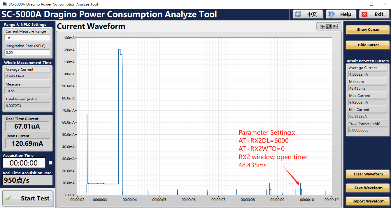
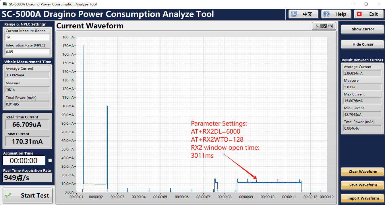
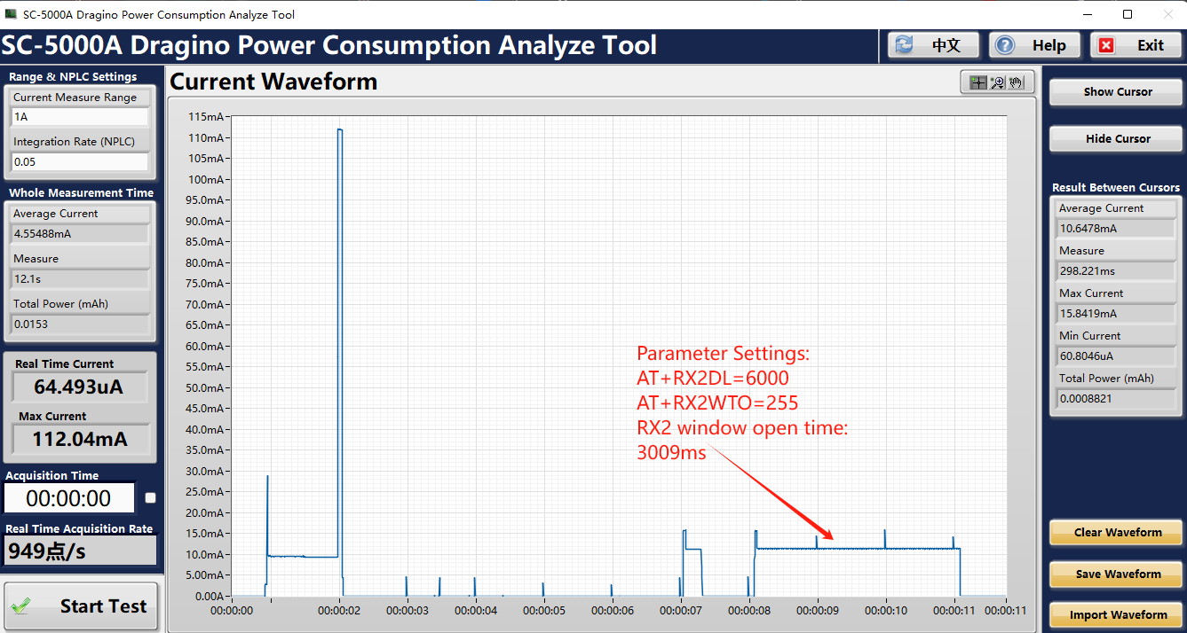
7.21 Get or Set RXwindows2 timeout
Feature: Get or Set the number of symbols to detect and timeout from RXwindow2(0 to 255).
AT Command: AT+RX2WTO
|Command Example|Function|Response |AT+RX2WTO=?|Get RXwindows2 timeout|7 OK
|AT+RX2WTO=20|Set RXwindows2 timeout|OK
Example: ~1. Set AT+RX2WTO=0, AT+RX2DL=6000, the window opening time is: 48.435ms
- Set AT+RX2WTO=128, AT+RX2DL=6000, the window opening time is: 3011ms
- Set AT+RX2WTO=255, AT+RX2DL=6000, the window opening time is: 3009ms
7.22 Setting up uplinkdwelltime (as923, au915)
Feature: Get or Set uplinkdwelltime
AT Command: AT+DWELLT
|Command Example|Function|Response |AT+DWELLT=?|Get uplinkdwelltime|1 OK
|AT+DWELLT=0|Set uplinkdwelltime|OK
Downlink Command: 0x25
Format: Command Code (0x25) followed by 1 bytes state value.
If the downlink payload=2501, it means set uplinkdwelltime to 1, while type code is 25.
-
Example 1: Downlink Payload: 2501
// set uplinkdwelltime to 1 -
Example 2: Downlink Payload: 2500
// set uplinkdwelltime to 0
7.23 Set Packet Receiving Response Level
Feature: Get or Set packet receiving response level. This feature is used to set compatible with different LoRaWAN servers. If RPL doesn;t match , user will see strange message in the server portal.
RPL value:
-
AT+RPL=0: Device won't immediately reply any downlink commands from platform.
-
AT+RPL=1: Device will immediately reply message to Unconfirmed Data Down. Payload is 0x00.
-
AT+RPL=2: Device will immediately reply message to Confirmed Data Down. Payload is 0x00 and requied response header for this command.
-
AT+RPL=3: Device will immediately reply message to MAC Command. Payload is 0x00 and requied response header for this command.
-
**AT+RPL=4: **Device will immediately reply message to Confirmed Data Down & MAC Command. Payload is 0x00 and requied response header for these two commands.
Case Analyes:
-
For Class A devices, AT+RPL=0 is ok. that is defaut settings in software.
-
For Class C devices used in ChirpStack, need to set AT+RPL=4 because Chirpstack require immedietely reply message to MAC Command.
-
For Class C devices used in TTI, need to set AT+RPL=4 because TTI require immediately reply message to Confirmed Data Down & MAC Command.
AT Command: AT+RPL
|Command Example|Function|Response |AT+RPL=?|Get packet receiving response level|1 OK
|AT+RPL=0|Set packet receiving response level|OK
Downlink Command: 0x21
Format: Command Code (0x21) followed by 1 bytes level value.
If the downlink payload=2101, it means set packet receiving response level to 1, while type code is 21.
-
Example 1: Downlink Payload: 2101
// set packet receiving response level to 1 -
Example 2: Downlink Payload: 2102
// set packet receiving response level to 2
7.24 Controls NBTrans in unconfirmed uplink mode(LWS007 NBTrans:Set retransmission packets)
**AT Command: AT+SETMAXNBTRANS **
|Command Example|Function|Response |AT+SETMAXNBTRANS=1,0|Value1: set the maximum NBTrans.|1 OK
|AT+SETMAXNBTRANS=?,1| value2: 0: uplink fcnt doesn't change for each NBTrans;
1: uplink fcnt increase by 1 for each NBTrans. | 1
OK
Downlink Command: 0x33
Format: Command Code (0x33) followed by 2 bytes mode value.
If the downlink payload=330100, it means set end node to use confirm mode, while type code is 33.
-
Example 1: Downlink Payload: 330100
// Set AT+SETMAXNBTRANS=1,0 -
Example 2: Downlink Payload: 330201
// Set AT+SETMAXNBTRANS=2,1
7.25 Device offline rejoining (LWS007)
AT Command: AT+DDETECT
AT+DDETECT=
-
ACK_Timout_1: Unit: min
-
ACK_Timout_2: Unit: min
|Command Example|Function|Response | AT+DDETECT=1,1440,2880
value1 |Enable online detect| 1
OK
| AT+DDETECT=1,?,2880
value2 |Online detection packet sending time|
OK
| AT+DDETECT=1,1440,?
value3 |Process rejoin|
OK
Downlink Command: 0x32
Format: Command Code (0x32) followed by 2 bytes mode value.
If the downlink payload=320105A00B40, it means set end node to use confirm mode, while type code is 32.
-
Example 1: Downlink Payload: 320105A00B40
// Set AT+DDETECT=1,1440,2880
** 0x01** : Flag**
     **0x05A0 **: ACK_Timout_1 : 1440minutes (24 hours)

     **0x0B40 **: ACK_Timout_2 : 2880minutes (48 hours)
- Explain: Enable Online Detect, if end node doesn't receive any downlink within ACK_Timout_1( 1440 minutes or 24 hours). End node will use confirmed uplink to send packets during ACK_Timout_1 (the 24th hour) to ACK_Timout_2 ( the 48th hour). If from the 24th to 48th hour, end node got an downlink from server, it will switch back to unconfirmed uplink. end node will restart ACK_Timout_1. If from the 24th to 48th hour, end node still not got any downlink, means device doesn't get ACK from server within last 48 hours. Device will process rejoin, rejoin request interval is AT+RJTDC period. For AU915/ US915, device will use the sub-band used for last join.
7.26 Request the server to send an ACK
Feature: Mode for sending data for which acknowledgment was not received. LoraWAN Network Server(eg. The Things NetWork/ChirpStack/AWS/...).
AT Command: AT+PNACKMD
|Command Example|Function|Response |AT+PNACKMD=1|If the node uploads the ACK as confirm, it will request the LoraWAN Network Server to send an ACK. If the LoraWAN Network Server ack is not received, the node will upload the packets that have not received the ACK the next time it receives the ACK|1 OK
|AT+PNACKMD=0(Default)|off request the LoraWAN Network Server to send an ACK|
OK
Downlink Command: 0x34
0X34 01 //Same As AT+PNACKMD=1
0x34 00 //Same As AT+PNACKMD=0
7.27 Adjust network rejoining interval
AT Command: AT+RJTDC
|Command Example|Function|Response |AT+RJTDC=?|Show the ReJoin data transmission interval in min| 20 (Default)
((( OK
the interval is 20 min
))) |AT+RJTDC=60|Set the ReJoin data transmission interval in min|OK Set the ReJoin data transmission interval to 60 min
Downlink Command: 0x26
Format: Command Code (0x26) followed by 2 bytes mode value.
If the downlink payload=26000A, it means set end node to use confirm mode, while type code is 26.
-
Example 1: Downlink Payload: 26000A
// Set AT+RJTDC=10 -
**Example 2: **Downlink Payload: 260002
// Set AT+RJTDC=2
8. AT Commands Combination
8.1 Set a fix RX2DR for downlink window
-
**AT+ADR=0 **
// Disable ADR first -
AT+RX2DR=xxxx
// Set xxxx to your wanted DataRate
8.2 Use Downlink Command to set a fix uplink DR
Downlink Command: 0x22000500
Same as: