DS03A-FB – NB-IoT/LTE-M Door Sensor
1. Introduction
1.1 What is DS03A-FB NB-IoT/LTE-M Door Sensor
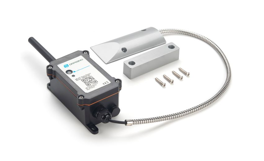
The Dragino DS03A-FB is an NB-IoT/LTE-M Door Sensor for Internet of Things solutions. It detects door open/close status and uploads the data to an IoT server via an NB-IoT or CAT-M1 network. Users can see the door status, door open counts and last door open duration on the IoT server.
DS03A-FB supports periodic uplinks and uplinks triggered by door open/close events. Users can disable the immediate open/close uplinks while the device continues to count door opening events and report data periodically.
DS03A-FB has an Alarm Base on Timeout feature. Users can configure the device to send an alarm when a door remains open or closed for a specified time. A repeat reminder interval can also be configured while the monitored status remains unchanged.
DS03A-FB supports single-channel and dual-channel door monitoring. Channel 1 uses PA8. Channel 2 uses PA4 and requires hardware with the second input connected.
DS03A-FB supports different uplink methods including MQTT, MQTTs, TCP or UDP for different application requirements, and supports uplinks to various IoT servers.
DS03A-FB supports BLE configuration, GNSS location reporting and HTTP OTA firmware updates.
DS03A-FB is designed for outdoor use with a weatherproof enclosure. It is powered by an 8500mAh Li-SOCl2 battery for long-term use. Actual battery life depends on network coverage, update interval, door event frequency, GPS settings and uplink method.
*Make sure you have NB-IoT or CAT-M1 coverage locally.
1.2 Features
- NB-IoT Bands: B1/B2/B3/B4/B5/B8/B12/B13/B17/B19/B20/B25/B26/B28/B65/B66/B85/B106
- CAT-M1 / LTE-M Bands: B1/B2/B3/B4/B5/B8/B12/B13/B18/B19/B20/B25/B26/B28/B66/B85/B106
- Ultra-low power consumption
- Door open/close detection
- Door open counts and last open duration
- Open/closed status timeout alarm
- Configurable continuous alarm reminder interval
- Single-channel or dual-channel monitoring
- Probe cable length: 40cm
- Multiple sampling records in one uplink
- Uplink via MQTT, MQTTs, TCP or UDP
- GNSS for location reporting
- Bluetooth remote configuration
- HTTP OTA firmware update
- Periodic and event-triggered uplinks
- Downlink to change configuration
- 8500mAh Li/SOCl2 Battery (DS03A-FB)
- Solar panel + 3000mAh Li-ion battery (DS03A-FS)
- Nano SIM card slot
1.3 Specification
Common DC Characteristics:
- Supply Voltage: 3.0V ~ 3.6V
- Operating Temperature: -40 ~ 85°C
Cellular Module: nRF9151-NGFF
Supported NB-IoT and LTE-M bands are listed in section 1.2. Select a SIM card and operator that support the required network and bands in the deployment area.
Door Sensor:
- Channel 1: PA8
- Channel 2: PA4, enabled with
AT+TTRCHANNEL=2on supported hardware - Door status: 0 = Closed; 1 = Open
- Last open duration unit: second
- Probe cable length: 40cm
Battery:
- Li-SOCl2 non-rechargeable battery
- Capacity: 8500mAh
- Self Discharge: <1% / Year @ 25°C
- Max continuous current: 130mA
- Max boost current: 2A, 1 second
Power Consumption:
- STOP Mode: 14uA @ 3.3v
- Max transmit power: 350mA @ 3.3v
1.4 Applications
- Door and window monitoring
- Warehouse and storage room monitoring
- Cabinet access monitoring
- Smart buildings and home automation
- Door left-open or closed-too-long alarms
1.5 Sleep mode and working mode
Deep Sleep Mode: The sensor does not activate the NB-IoT/CAT-M1 network. This mode is used for storage and shipping to save battery life.
Working Mode: The sensor joins the NB-IoT/CAT-M1 network and sends sensor data to the server. Between sampling and communication activities, the sensor enters a low-power idle state.
1.6 Button & LEDs
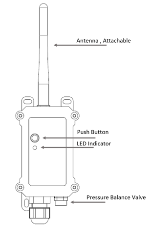
| Behavior on ACT | Function | Action |
|---|---|---|
 1~3s | Send an uplink | If sensor has already attached to NB-IoT/CAT-M1 network, sensor will send an uplink packet, blue led will blink once. |
 >3s | Active Device | Green led will fast blink 5 times. And then start to attach NB-IoT/CAT-M1 network. |
 x5 | Deactivate Device | Red led will solid on for 5 seconds. Means device is in Deep Sleep Mode. |
| x1 | Toggle Serial Communication | Press the ACT button once to activate the serial communication function, and Ready will be displayed in the serial tool. |
Note: When the device is executing a program, the buttons may become invalid. It is best to press the buttons after the device has completed the program execution.
1.7 BLE connection
DS03A-FB supports BLE remote configuration. BLE can be used to configure sensor parameters or view console output.
BLE is activated in the following cases:
- Press the button to send an uplink.
- Press the button to activate the device.
- Power on or reset the device.
If no BLE connection is established within 60 seconds, the sensor shuts down BLE to enter low-power mode.
See BLE Configure Instruction. For firmware updates, use the FB update methods in section 5.
1.8 Pin Definitions, Switch & SIM Direction
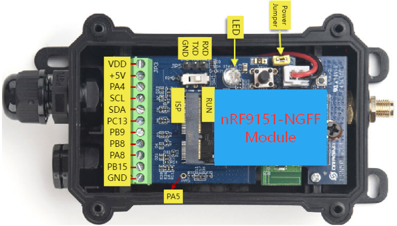
DS03A-FB door sensor inputs are PA8 (channel 1) and PA4 (channel 2).
1.8.1 Jumper JP2
Install this jumper to power on the device. Remove it to power off the device.
1.8.2 BOOT MODE / SW1
The BOOT MODE / SW1 switch has no function on -FB products. Always keep the switch in the FLASH position.
1.8.3 Reset Button
Press to reboot the device.
1.8.4 SIM Card Direction
1.8.5 Door Sensor Channels
| Channel | Input | Configuration |
|---|---|---|
| Channel 1 | PA8 | Used in single-channel and dual-channel modes. |
| Channel 2 | PA4 | Requires AT+TTRCHANNEL=2 and hardware with a second door sensor input connected. |
Enabling dual-channel mode does not add a second physical probe. Confirm the supplied hardware and wiring before using channel 2.
1.9 Mechanical
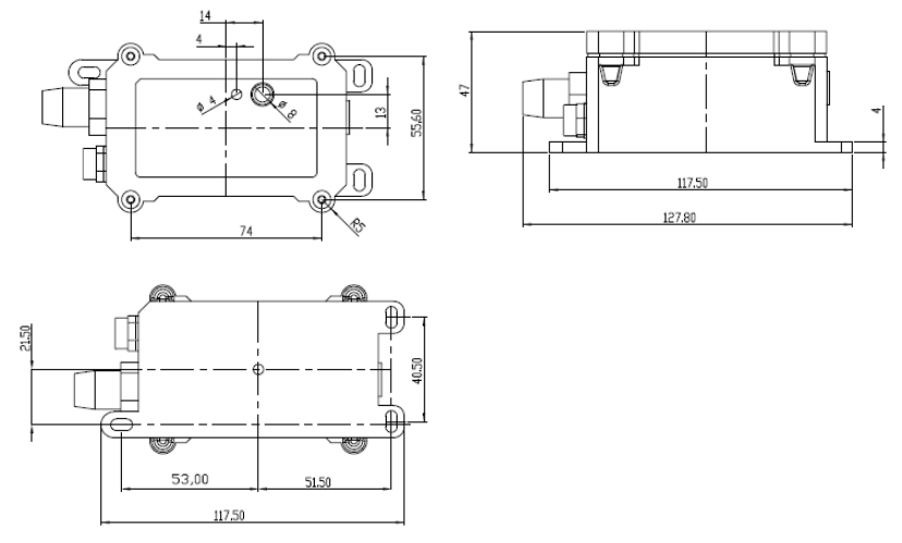
Probe Mechanical:
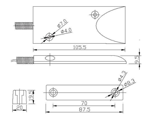
1.10 Magnet Distance
- Wood door: 10mm ~ 30mm
- Iron door: 30mm ~ 45mm
Check the actual open/close status after installation. Door material, alignment and mounting position can affect detection.
2. Use DS03A-FB to communicate with IoT Server
2.1 Send data to IoT server via NB-IoT/CAT-M1 network
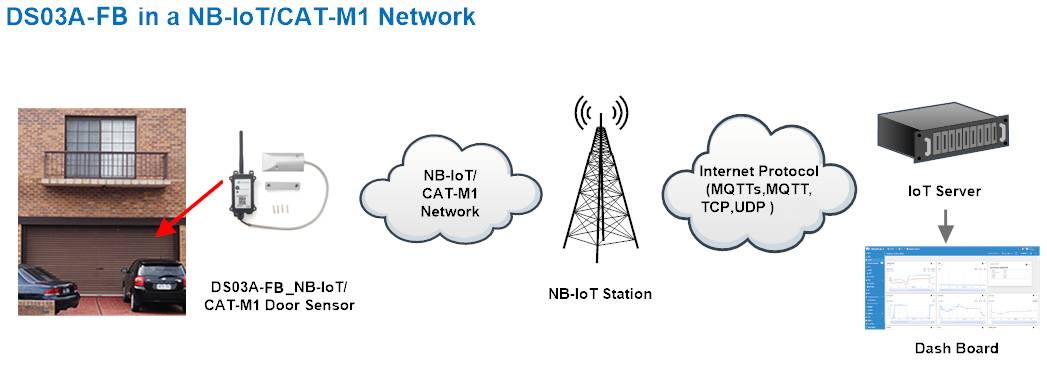
DS03A-FB uses the nRF9151-NGFF cellular module to upload door sensor data through the local NB-IoT/CAT-M1 network. The data is forwarded to the IoT server using the configured protocol.
Below shows the network structure:
GE Version: This version does not include a SIM card or a preconfigured IoT server. Configure the following:
- Install a compatible SIM card and configure the APN. See Attach Network.
- Set the server address and connection parameters. See Configure to Connect Different Servers.
Below shows examples of server connections.
| Servers | Dash Board | Comments |
|---|---|---|
| Node-Red | 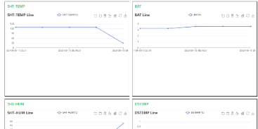 | Map the DS03A-FB JSON fields to the dashboard. |
| DataCake | 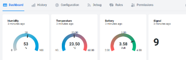 | Use the DS03A-FB payload format. |
| Tago.IO | ||
| General UDP | Raw JSON payload | Developer-designed dashboard required. |
| General MQTT | Raw JSON payload | Developer-designed dashboard required. |
| ThingsBoard | 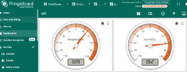 |
1T Version: The FB series also provides a version with a pre-installed 1NCE SIM and ThingsEye configuration. For the supplied SIM/server option, check the order label. See ThingsEye Config Instruction.
2.2 Payload Types
DS03A-FB supports JSON payloads only. Use AT+PRO to select the connection protocol with the corresponding parameters:
AT+PRO=2,0// UDP connection with JSON payloadAT+PRO=3,0// MQTT connection with JSON payloadAT+PRO=4,0// TCP connection with JSON payload
The default is AT+QGPS=0 // The GPS function is not enabled. Therefore, the GPS collection time in the following example paylaod does not follow the system time, and the latitude and longitude are 0.
2.2.1 Status Packet
Each time the device is reactivated and connects to the server, it sends a status packet containing device and firmware information.
Example payload:
{
  "IMEI": "355025936334455",
  "Image Version": "v1.0.4",
  "NB-IoT Stack": "NRF9151-001",
  "Model": "DS03A-FB"
}
| Field | Description |
|---|---|
IMEI | International Mobile Equipment Identity of the device. |
Image Version | Device firmware version. |
NB-IoT Stack | Cellular stack identifier reported by the device. |
Model | Device model. |
2.2.2 General JSON Format
Single-channel example:
With AT+TTRCHANNEL=1, channel 2 fields are still present, but should not be interpreted as a second monitored door in single-channel mode.
{
  "IMEI": "355025936334455",
  "IMSI": "460240275256466",
  "Model": "DS03A-FB",
  "fcnt": "8",
  "work_mode": 1,
  "signal": "29",
  "bat": 3.65,
  "level_status": 1,
  "alarm_status": 0,
  "door_open_num": 4,
  "last_open_time": 3,
  "level_status2": 1,
  "alarm_status2": 0,
  "door_open_num2": 0,
  "last_open_time2": 0,
  "time": "2026-11-13T01:54:22Z",
  "latitude": 0.000000,
  "longitude": 0.000000,
  "gps_time": "00/00/00,00:00:00",
  "1": ["0,2,1,2026-11-13T01:51:05Z"],
  "2": ["0,2,1,2026-11-13T01:51:09Z"],
  "3": ["1,3,1,2026-11-13T01:51:33Z"],
  "4": ["1,3,1,2026-11-13T01:52:09Z"],
  "5": ["1,3,1,2026-11-13T01:53:09Z"],
  "6": ["1,3,1,2026-11-13T01:54:09Z"],
  "7": ["0,3,3,2026-11-13T01:54:10Z"],
  "8": ["1,4,3,2026-11-13T01:54:22Z"]
}
Dual-channel example:
The following example shows a channel 2 timeout alarm in dual-channel mode.
{
  "IMEI": "355025936334455",
  "IMSI": "460240275256466",
  "Model": "DS03A-FB",
  "fcnt": "26",
  "work_mode": 1,
  "signal": "23",
  "bat": 3.63,
  "level_status": 0,
  "alarm_status": 0,
  "door_open_num": 0,
  "last_open_time": 36,
  "level_status2": 1,
  "alarm_status2": 1,
  "door_open_num2": 2,
  "last_open_time2": 1,
  "time": "2026-11-13T06:48:23Z",
  "latitude": 0.000000,
  "longitude": 0.000000,
  "gps_time": "00/00/00,00:00:00",
  "1": ["0,0,36,2026-11-13T06:45:45Z"],
  "2": ["0,0,36,2026-11-13T06:45:48Z"],
  "3": ["0,0,36,2026-11-13T06:45:56Z"],
  "4": ["0,0,36,2026-11-13T06:46:56Z"],
  "5": ["0,0,36,2026-11-13T06:47:50Z"],
  "6": ["0,0,36,2026-11-13T06:47:53Z"],
  "7": ["0,0,36,2026-11-13T06:47:56Z"],
  "8": ["0,0,36,2026-11-13T06:48:23Z"]
}
Device and sensor fields:
| Field | Description |
|---|---|
IMEI | Device identifier, reported as a string. |
IMSI | SIM subscriber identifier, reported as a string. |
Model | Device model: DS03A-FB. |
fcnt | Uplink frame counter, reported as a string. |
work_mode | Working-mode value reported by the firmware (only mode 1). |
signal | Cellular signal indicator, reported as a string. |
bat | Battery voltage in volts. 3.65 means 3.65V. |
level_status | Channel 1 (PA8) door status: 0 = Closed; 1 = Open. |
alarm_status | Channel 1 timeout-alarm trigger flag: 1 for the initial timeout-triggered alarm packet; 0 for normal uplinks and repeat reminders. |
door_open_num | Channel 1 door open count. Counting/reset behavior is selected with AT+COUNTMOD. |
last_open_time | Channel 1 last recorded door open duration, in minutes. |
level_status2 | Channel 2 (PA4) door status: 0 = Closed; 1 = Open. Use only when channel 2 is enabled and connected. |
alarm_status2 | Channel 2 timeout-alarm trigger flag. Same interpretation as alarm_status. |
door_open_num2 | Channel 2 door open count. |
last_open_time2 | Channel 2 last recorded door open duration, in minutes. |
time | Device timestamp in UTC. Z denotes UTC. |
latitude, longitude | GNSS coordinates. |
gps_time | Time of the GPS position fix, separate from the device timestamp. |
alarm_status and alarm_status2 indicate timeout alarm triggering, not a continuously latched alarm state. Repeat reminders generated by AT+TTRALARM have the corresponding alarm flag set to 0, even while the timeout condition persists. Use the door status and configured timeout logic as well as the flag when displaying alarms.
Historical samples:
With AT+CLOCKLOG=1,65535,1,8, numbered keys "1" through "8" contain up to eight records. Each value is a JSON array containing one comma-separated string:
"level_status,door_open_num,last_open_time,sampling time (UTC)"
Example: "8":["0,0,36,2026-11-13T06:48:23Z"] means channel 1 was closed, the count was 0 and the last open duration was 36 seconds at the indicated time.
The numbered historical records contain channel 1 only, including in dual-channel mode. Channel 2 is reported in the top-level fields.
Signal strength:
The cellular signal quality indicator is reported as a string.
| Value | Signal strength |
|---|---|
"0" | −113 dBm or less |
"1" | −111 dBm |
"2"–"30" | −109 dBm to −53 dBm |
"31" | −51 dBm or greater |
"99" | Unknown or not detectable |
GPS fields:
gps_time: Timestamp of the GPS position fix, separate fromtime. In this example, GPS is disabled and the field contains the placeholder"00/00/00,00:00:00".latitudeandlongitude: GPS coordinates in decimal degrees. For example,22.706150and114.242830mean 22.706150° N and 114.242830° E.
3.1 Configure Methods
DS03A-FB supports the following configuration methods:
- AT commands via Bluetooth (Recommended): BLE Configure Instruction.
- AT commands via UART: UART Connection.
- Server downlinks for supported configuration commands.
3.2 Serial Access Password
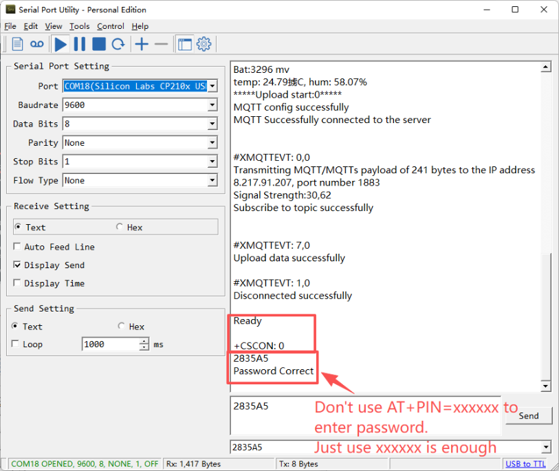
After connecting by Bluetooth or UART, enter the six-character Serial Access Password printed on the device box label to access the AT command window. The label shows the initial password as AT+PIN=xxxxxx; use the printed six-character password to log in.
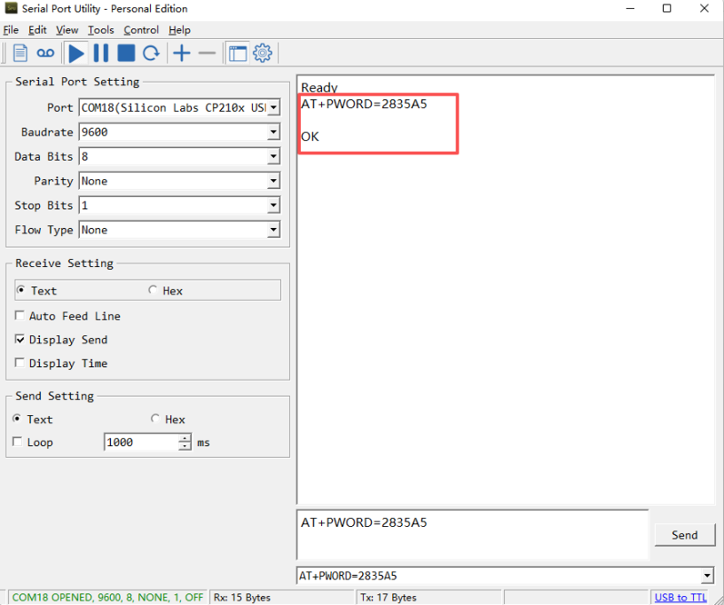
To change the password, use AT+PWORD=xxxxxx (6 characters).
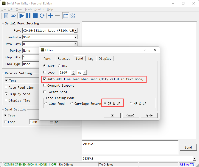
Note: Add a line break after each command, or enable automatic line breaks in the Bluetooth/UART tool.
3.3 AT Commands Set
AT?                  // List available commands
AT+<CMD>?            // Help on a command
AT+<CMD>             // Run a command
AT+<CMD>=<value>     // Set a value
AT+<CMD>=?           // Query a value
General Commands
| Command | Function |
|---|---|
AT+MODEL | Get module information. |
AT+CFG | Print all settings. |
AT+DEUI | Get or set the Device ID. |
AT+CFGMOD | Working mode selection; query command help before changing. |
AT+TDC | Get or set the periodic transmission interval in seconds. |
AT+APN, AT+AUNAME, AT+APWD | Configure APN and APN credentials. |
AT+SERVADDR | Get or set server address. |
AT+PRO | Select connection protocol. |
AT+RXDL | Get or set receiving time. |
AT+5VT | Get or set 5V power extension time. |
AT+GETSENSORVALUE | Get current sensor measurements. |
AT+INTMOD | Get or set interrupt trigger mode. |
AT+SLEEP | Set sleep mode. |
AT+IOTMOD | Configure network categories and priority. |
AT+SFNT | Get or set network search time; use device help for parameters. |
AT+QCOPS | Get or set operator code. |
Door Sensor Commands
| Command | Function |
|---|---|
AT+DISALARM | Enable/disable immediate door open/close event uplinks. |
AT+TTRCHANNEL | Select single-channel or dual-channel monitoring. |
AT+TTRIG1, AT+TTRIG2 | Configure channel 1/channel 2 timeout alarms. |
AT+TTRALARM | Set repeat reminder interval in minutes. |
AT+COUNTMOD | Select accumulating or per-TDC count mode. |
AT+CLRC | Clear current door open counts. |
MQTT Management
AT+CLIENT, AT+UNAME, AT+PWD, AT+PUBTOPIC, AT+SUBTOPIC, AT+MQOS, AT+TLSMOD.
GPS
AT+GTIME: positioning time; AT+QGPS: enable/disable GPS; AT+QGTDC: positioning interval in hours.
Data, Maintenance and Debugging
AT+CLOCKLOG, AT+PDTA, AT+PLDTA, AT+CLRDTA, AT+LDATA, AT+REDPT, AT+UDPMOD, AT+DEBUG, AT+GETLOG, AT+FREB, AT+UPGRADE, AT+FDR, AT+PWORD, ATZ.
Use AT? to list available commands and AT+<CMD>? to check command parameters.
3.4 Test Uplink and Change Update Interval
AT Command: AT+TDC
AT+TDC=?        // Query current interval
AT+TDC=7200     // Set interval to 7200 seconds (2 hours)
Downlink Command: 0x01
Format: Command code followed by 3 bytes representing seconds, most significant byte first.
Example: 01 00 A8 C0 → AT+TDC=43200 (12 hours).
The new TDC setting takes effect after the next button-triggered uplink or periodic TDC uplink. Timeout alarms and their continuous reminders do not activate the new TDC setting. After changing TDC, press ACT for 1~3 seconds to send an uplink, or wait for the next existing periodic uplink before checking the new interval.
3.5 Extend the receiving time
AT Command: AT+RXDL
Example: AT+RXDL=1000 // Extend the receiving time to 1000ms.
Downlink Command: 0x03
Format: Command code followed by 3 bytes.
Example: 03 00 03 E8 → AT+RXDL=1000.
3.6 Reset
AT Command: ATZ
Reboot the MCU.
Downlink Command: 04 FF.
3.7 +5V
Feature: Set the extension time of the 5V power output, in milliseconds.
AT Command: AT+5VT
Example: AT+5VT=2000.
Downlink Command: 0x05
Format: Command code followed by 3 bytes.
Example: 05 00 07 D0 → AT+5VT=2000.
3.8 Trigger an uplink by external interrupt
The AT+INTMOD command is only applicable to Channel 1 (uses PA8).
Select the interrupt trigger mode for Channel 1 with AT+INTMOD:
| Command | Function |
|---|---|
AT+INTMOD=0 | Disable interrupt-triggered uplinks. |
AT+INTMOD=1 | Trigger on rising and falling edges. |
AT+INTMOD=2 | Trigger on falling edge. |
AT+INTMOD=3 | Trigger on rising edge. |
Downlink Command: 0x06
Format: Command code followed by 3 bytes.
06 00 00 01→AT+INTMOD=1.06 00 00 03→AT+INTMOD=3.
For normal open/close monitoring, use both-edge triggering with immediate event reporting enabled (AT+DISALARM=0).
Channel 2 (uses PA4) is enabled through AT+TTRCHANNEL=2. Its trigger mode is permanently fixed to both-edge (rising and falling) triggering and cannot be configured by AT+INTMOD
3.9 Set the QoS level
AT Command: AT+MQOS=xx // MQTT QoS level, 0~2.
Downlink Command: 0x07, followed by 1 byte.
07 00→AT+MQOS=0.07 01→AT+MQOS=1.
3.10 Set the TLS mode
See General MQTT over TLS Connection.
AT Command: AT+TLSMOD
AT+TLSMOD=0,0// Disable TLS.AT+TLSMOD=1,0// Enable TLS without peer authentication.AT+TLSMOD=1,1// Perform server authentication.AT+TLSMOD=1,2// Perform server and client authentication if requested by the remote server.
Downlink Command: 0x09, followed by 2 bytes.
09 00 00→AT+TLSMOD=0,0.09 01 02→AT+TLSMOD=1,2.
Use server authentication for production connections where supported, and configure the required certificates according to the FB general manual.
3.11 Configure Network Category to be Searched for under LTE RAT
AT Command: AT+IOTMOD=a,b,c
- a: 0 = Disable eMTC; 1 = Enable eMTC.
- b: 0 = Disable NB-IoT; 1 = Enable NB-IoT.
- c: Network category priority when both categories are enabled.
Example: AT+IOTMOD=1,1,2 // Enable both eMTC and NB-IoT, with NB-IoT priority.
3.12 Factory data reset
AT Command: AT+FDR
Reset parameters to factory defaults. Record server, SIM/APN and application settings before performing a factory reset.
3.13 Print last few data entries
AT Command: AT+PLDTA
Example: AT+PLDTA=5 // Print the last 5 stored entries.
Use this command to check saved sensor data and timestamps. No downlink command is specified for this feature.
3.14 Print data entries based on page
AT Command: AT+PDTA
Example: AT+PDTA=1,1 // Print data from page 1 to page 1.
No downlink command is specified for this feature.
3.15 Clear Flash Record
AT Command: AT+CLRDTA
Clear stored sensor history. Wait until erasing completes before further operations.
Downlink Command: 32 00.
Note: This command clears data-log storage. To clear door counts, use AT+CLRC instead. Clearing stored history is irreversible.
3.16 Debug mode
The nRF9151 platform requires serial communication to be activated before UART use.
AT+DEBUG=1// Enter debug mode.AT+DEBUG=0// Exit debug mode and disable serial communication.
The common FB debug mode remains active for 5 minutes and then turns off automatically. Keeping the serial port active increases sleep power consumption. Exit debug mode after configuration.
3.17 Set GNSS open time
AT Command: AT+GTIME
Example: AT+GTIME=30 // Set GPS positioning time to 30 seconds.
Downlink Command: 0x10, followed by 2 bytes.
Example: 10 00 1E → AT+GTIME=30.
3.18 Turn on/off GPS
AT Command: AT+QGPS
AT+QGPS=0// Turn off GPS.AT+QGPS=1// Turn on GPS.
Downlink Command: 0x11, followed by 1 byte.
Example: 11 01 → AT+QGPS=1.
3.19 Set GPS positioning interval
AT Command: AT+QGTDC
Example: AT+QGTDC=24 // Set positioning interval to 24 hours.
When GPS is enabled, the device performs positioning according to the configured interval after activation.
Downlink Command: 0x12, followed by 3 bytes.
Example: 12 00 00 18 → AT+QGTDC=24.
3.20 Enable / Disable immediate event uplinks
AT Command: AT+DISALARM
| Command | Function |
|---|---|
AT+DISALARM=0 | Enable immediate door open/close uplinks as well as periodic uplinks. |
AT+DISALARM=1 | Disable immediate door open/close uplinks. Door counting and periodic reporting continue. |
AT+DISALARM=1 disables only immediate open/close event uplinks. It does not disable timeout alarms configured by AT+TTRIG1 / AT+TTRIG2, or their repeat reminders configured by AT+TTRALARM.
For periodic-only door reporting without timeout reminders, also disable both timeout alarms with AT+TTRIG1=0,0, AT+TTRIG2=0,0, and repeat reminders with AT+TTRALARM=0.
3.21 Number of door sensor channels
AT Command: AT+TTRCHANNEL
| Command | Function |
|---|---|
AT+TTRCHANNEL=1 | Single-channel mode: PA8 only (default single-channel operation). |
AT+TTRCHANNEL=2 | Dual-channel mode: PA8 and PA4. Requires supported hardware and wiring. |
3.22 Alarm Base on Timeout
DS03A-FB can monitor how long a door remains in a specified status after a status change.
AT Commands:
AT+TTRIG1=keep_status,keep_time// Channel 1, PA8.AT+TTRIG2=keep_status,keep_time// Channel 2, PA4. (RequiresAT+TTRCHANNEL=2to enable first).
Parameters:
- keep_status:
1: Monitor close-to-open event (door remains open too long).0: Monitor open-to-close event (door remains closed too long).
- keep_time: Timeout in seconds, range 0~65535. Set to 0 to disable the timeout alarm.
Channel 1 (PA8) Configuration
AT Command to configure:
AT+TTRIG1=1,30→ Trigger if status changes to open and remains open for >30s. Thealarm_statusbit in the uplink payload is set to1.AT+TTRIG1=0,30→ Trigger if status changes to close and remains closed for >30s. Thealarm_statusbit in the uplink payload is set to1.AT+TTRIG1=0,0→ Default. Disable timeout alarm for Channel 1.
Downlink Command to configure:
Example:
0x0D 00 00 00 01 00 00 00 1Eequals toAT+TTRIG1=1,30(0x1E = 30)0x0D 00 00 00 00 00 00 00 00equals toAT+TTRIG1=0,0
Channel 2 (PA4) Configuration
AT Command to configure:
AT+TTRIG2=1,30→ Trigger if status changes to open and remains open for >30s. Thealarm_status2bit (2nd bit of the 12th payload byte) is set to1.AT+TTRIG2=0,30→ Trigger if status changes to close and remains closed for >30s. Thealarm_status2bit is set to1.AT+TTRIG2=0,0→ Default. Disable timeout alarm for Channel 2.
Downlink Command to configure:
Example:
0x0F 00 00 00 01 00 00 00 1Eequals toAT+TTRIG2=1,30(0x1E = 30)0x0F 00 00 00 00 00 00 00 3Cequals toAT+TTRIG2=0,60(0x3C = 60)
3.23 TTRIG timeout repeat alarm interval
AT Command: AT+TTRALARM
Set the repeat reminder interval for channel 1/channel 2 timeout alarms, in minutes (Range: 0~255). Use together with AT+TTRIG1 / AT+TTRIG2.
AT+TTRALARM=0// Disable repeat reminders.AT+TTRALARM=1// Repeat every 1 minute while the timeout condition persists.AT+TTRALARM=60// Repeat every 60 minutes.
Repeat reminders stop when the door leaves the monitored status.
Downlink Command: 0x0A
Format: Command Code (0x0A) followed by 1 byte.
Examples:
0A 00// Same asAT+TTRALARM=0(Disable repeat reminders).0A 3C// Same asAT+TTRALARM=60(60 in decimal equals 0x3C in HEX).
Repeat reminder packets have alarm_status=0 / alarm_status2=0. Only the initial timeout-triggered packet sets the corresponding flag to 1. Disabling repeat reminders does not disable the initial timeout alarm.
3.24 Clear current door open count
AT Command: AT+CLRC
Clear current door open counts.
Downlink Command: A0 00 → AT+CLRC.
3.25 Count Mode
AT Command: AT+COUNTMOD
| Command | Function |
|---|---|
AT+COUNTMOD=0 | Keep accumulating the door open count. |
AT+COUNTMOD=1 | Reset the count after each periodic TDC uplink, then start counting again. |
Downlink Command: 0xA1
Format: Command Code (0xA1) followed by 1 byte.
- Example: A100 //Same as AT+COUNTMOD=0
- Example: A101 //Same as AT+COUNTMOD=1
3.26 Clock logging
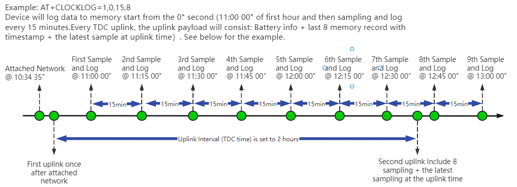
Sometimes when we deploy lots of end nodes in field. We want all sensors sample data at the same time, and upload these data together for analyze. In such case, we can use clock loging feature.
We can use this command to set the start time of data recording and the time interval to meet the requirements of the specific collection time of data.
AT command: AT+CLOCKLOG=a,b,c,d
a: 0: Disable Clock logging. 1: Enable Clock Logging
b: Specify First sampling start second: range (0 ~ 3599, 65535) // Note: If parameter b is set to 65535, the log period starts after the node accesses the network and sends packets.
c: Specify the sampling interval: range (0 ~ 255 minutes)
d: How many entries should be uplink on every TDC (max 16)
Note: To disable clock recording, set the following parameters: AT+CLOCKLOG=1,65535,0,0
Example:
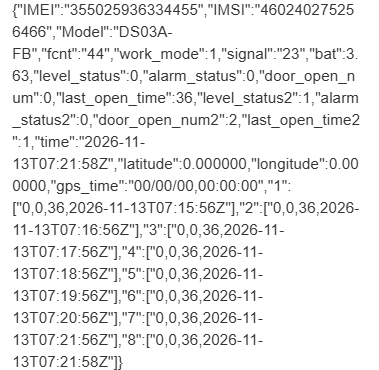
AT+CLOCKLOG=1,65535,1,8
After the node sends the first packet, data is recorded to memory at intervals of 1 minute. For each subsequent TDC uplink, the payload includes the full real-time device data as well as the last 8 memory records (level_status, door_open_num, last_open_time, sampling time).
Users need to synchronize the server time before configuring this command. If the server time is not synchronized before this command is configured, the command takes effect only after the node is reset.
Downlink command: 0x08
Format: Command Code (0x08) followed by 5 bytes.
-
Example 1: Downlink Payload: 08 01 FFFF 0F 08 // Set SHT record time: AT+CLOCKLOG=1,65535,15,8
-
Example 2: Downlink Payload: 08 01 04B0 0F 08 // Set SHT record time: AT+CLOCKLOG=1,1200,15,8
When entering the downlink payload, there must be no Spaces between bytes.
3.27 Automatic reboot after repeated send failures
AT Command: AT+FREB
Example: AT+FREB=15 // Automatically reboot after 15 consecutive send failures.
The default failure threshold is 15. Use AT+FREB=? to check command parameters before changing the threshold.
4. Battery & Power Consumption
DS03A-FB use ER26500 + SPC1520 battery pack and DS03A-FS use 3000mAh Recharable Battery with Solar Panel. See below link for detail information about the battery info and how to replace.
Battery Info & Power Consumption Analyze .
5. Firmware update
5.1 Over-the-Air (OTA) Firmware Update via HTTP
For detailed OTA update instructions, see OTA Upgrade for NB-IoT / LTE-M End Nodes.
Note: Users can upload the firmware binary to any public HTTP server (not a local/private network address) that the device can access, then use the following method to upgrade
Perform the following steps:
① Place the firmware binary (e.g., DS03A-FB.bin) on an HTTP-accessible server.
② Use a serial port or send the following command to the device: AT+UPGRADE=<firmware_url>
Example: AT+UPGRADE=http://repo.dragino.com/release/NB/DS03A-FB.bin
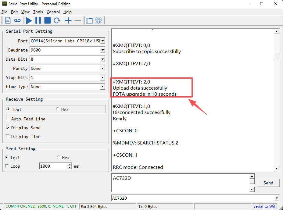
After the node receives the upgrade command via downlink, it will perform the upgrade automatically as shown below:
5.2 Firmware Update through UART TTL interface
-
Firmware and changelog can be downloaded from : Firmware download link
-
For detailed instructions on how to perform an update via USB TTL, please refer to this link: UART Upgrade for -FB/-FS/-FE models
6. FAQ
6.1 Where can I find common FB network and server configuration instructions?
See -FB & -FS Models (NB-IoT, LTE-M).
6.2 Why are channel 2 fields present in single-channel mode?
The JSON payload includes both sets of top-level door fields even with AT+TTRCHANNEL=1. Only channel 1 is enabled in that mode. Enable AT+TTRCHANNEL=2 and connect supported second-channel hardware before using channel 2 readings.
6.3 Why does the device still send alarms after AT+DISALARM=1?
This setting disables immediate open/close event uplinks only. Timeout alarms and repeat reminders remain active. Disable the corresponding AT+TTRIG1, AT+TTRIG2 and AT+TTRALARM settings if they are not needed.
6.4 Why is alarm_status 0 in a repeat alarm packet?
The timeout trigger flag is set to 1 for the initial timeout-triggered packet, not latched for the entire alarm period. Repeat reminders have a flag of 0. See sections 2.2.2 and 3.23.
6.5 Why does a new TDC interval not take effect immediately?
The new configuration takes effect after the next button-triggered or periodic TDC uplink. Timeout alarm packets and repeat reminders do not apply the new interval. Send a button-triggered uplink after configuration and then check the periodic timing.
6.6 Does this device support GPS positioning?
Yes. Use the FB commands AT+QGPS, AT+GTIME and AT+QGTDC. See Add Location Data on Uplink Packet.
6.7 Why does the dual-channel history not contain channel 2 data?
Numbered history entries contain channel 1 data only, including during dual-channel operation. Channel 2 values are available in top-level fields.
7. Order Info
Part Number: DS03A-FB-XX
Common FB series options:
- GE: General version, excluding SIM card.
- 1T: With 1NCE 10-year / 500MB SIM and preconfiguration for ThingsEye.
Confirm the available DS03A-FB option and the number of supplied door probes when ordering. Enabling dual-channel firmware mode does not imply that two probes are included.
8. Packing Info
Package Includes:
- DS03A-FB NB-IoT/LTE-M Door Sensor x 1
- External antenna x 1
Confirm the magnetic contact/probe set and mounting accessories against the supplied packing list.
9. Support
-
Support is provided Monday to Friday, from 09:00 to 18:00 GMT+8. Due to different time zones, live support may not be available. Questions will be answered as soon as possible during support hours.
-
Include the product model, firmware version, relevant settings, original payloads and steps to reproduce the issue. Send enquiries to Support@dragino.cc.