DDS75-FB – NB-IoT,LTE-M Distance Detection Sensor
1. Introduction
1.1 What is DDS75-FB NB-IoT Distance Detection Sensor
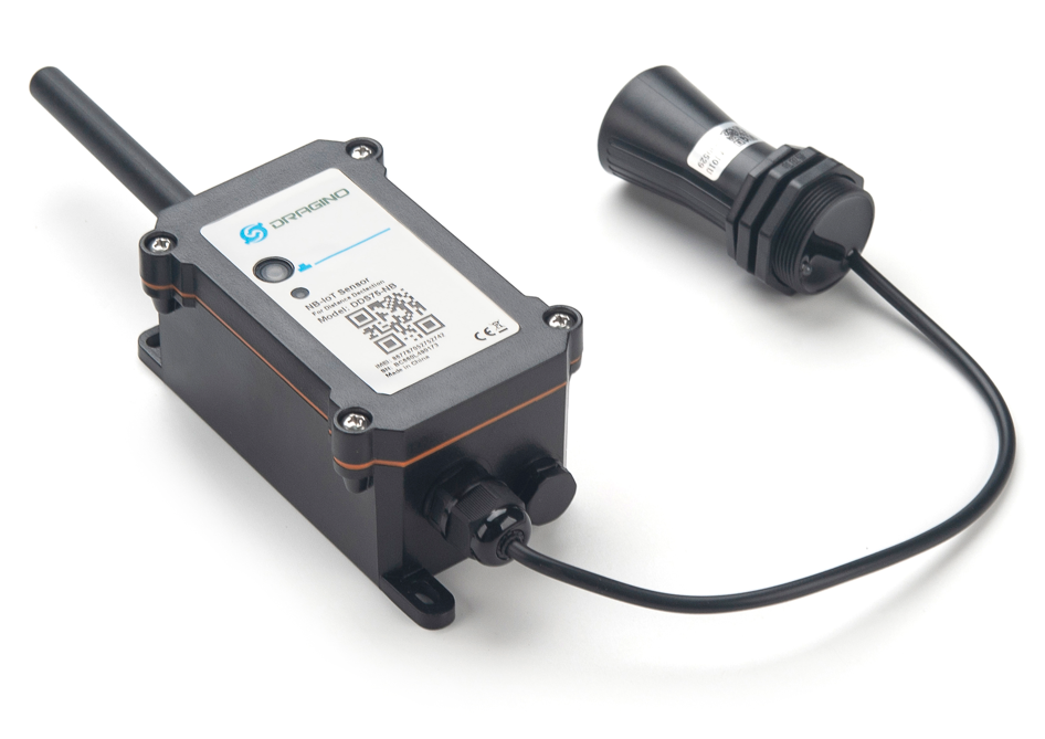
The Dragino DDS75-FB is a NB-IoT/LTE-M Distance Detection Sensor for Internet of Things solution. It is used to measure the distance between the sensor and a flat object. The distance detection sensor is a module that uses ultrasonic sensing technology for distance measurement, and temperature compensation is performed internally to improve the reliability of data. The DDS75-FB can be applied to scenarios such as horizontal distance measurement, liquid level measurement, parking management system, object proximity and presence detection, intelligent trash can management system, robot obstacle avoidance, automatic control, sewer, bottom water level monitoring, etc.
It detects the distance between the measured object and the sensor, and send IoT platform via NB-IoT/CAT-M1 network.
DDS75-FB supports different uplink methods including MQTT, MQTTs, UDP or TCP for different application requirement, and support uplinks to various IoT Servers.
DDS75-FB supports BLE configure and Over-the-Air (OTA) Update which make user easy to use.
DDS75-FB is powered by 8500mAh Li-SOCI2 battery, it is designed for long-term use up to several years.
DDS75-FB has optional built-in SIM card and default IoT server connection version. Which makes it works with simple configuration.
1.2 Features
- NB-IOT Bands: B1/B2/B3/B4/B5/B8/B12/B13/B18/B19/ B20/B25/B28/B66/B71/B85
- LTE-M/Cat-M Bands: B1/B2/B3/B4/B5/B8/B12/B13/B18/B19/ B20/B25/B26/B27/B28/B66/B85
- Ultra-low power consumption
- Distance Detection by Ultrasonic technology
- Flat object range 280mm - 7500mm
- Accuracy: ±(1cm+S*0.3%) (S: Distance)
- Measure Angle: 40°
- Multiply Sampling and one uplink
- Uplink via MQTT, MQTTs, TCP or UDP
- GNSS for Location Report
- Support Bluetooth v5.1 remote configure and update firmware
- Uplink on periodically
- Downlink to change configure
- IP66 Waterproof Enclosure
- 8500mAh Li/SOCl2 Battery (DDS75-FB)
- Solar panel + 3000mAh Li-ion battery (DDS75-FS)
- Nano SIM card slot for NB-IoT SIM
1.3 Specification
Common DC Characteristics:
- Supply Voltage: 3.0v ~ 3.6v
- Operating Temperature: -40 ~ 85°C
NB-IoT/LTE-M Spec:
- Module: nRF9151-NGFF
- Support Bands:
-
NB-IoT Bands:
- B1 @H-FDD: 2100MHz
- B2 @H-FDD: 1900MHz
- B3 @H-FDD: 1800MHz
- B4 @H-FDD: 2100MHz
- B5 @H-FDD: 860MHz
- B8 @H-FDD: 900MHz
- B12 @H-FDD: 720MHz
- B13 @H-FDD: 740MHz
- B17 @H-FDD: 730MHz
- B19 @H-FDD: 870MHz
- B20 @H-FDD: 790MHz
- B25 @H-FDD: 1900MHz
- B26 @H-FDD: 876MHz
- B28 @H-FDD: 750MHz
- B65 @H-FDD: 2155MHz
- B66 @H-FDD: 2000MHz
- B85 @H-FDD: 700MHz
- B106 @H-FDD: 900MHz
-
CAT-M1 / LTE-M Bands:
- B1 @H-FDD: 2100MHz
- B2 @H-FDD: 1900MHz
- B3 @H-FDD: 1800MHz
- B4 @H-FDD: 2100MHz
- B5 @H-FDD: 860MHz
- B8 @H-FDD: 900MHz
- B12 @H-FDD: 720MHz
- B13 @H-FDD: 740MHz
- B18 @H-FDD: 870MHz
- B19 @H-FDD: 870MHz
- B20 @H-FDD: 790MHz
- B25 @H-FDD: 1900MHz
- B26 @H-FDD: 876MHz
- B28 @H-FDD: 750MHz
- B66 @H-FDD: 2000MHz
- B85 @H-FDD: 700MHz
- B106 @H-FDD: 900MHz
-
Battery:
- Li/SOCI2 un-chargeable battery
- Capacity: 8500mAh
- Self Discharge: <1% / Year @ 25°C
- Max continuously current: 130mA
- Max boost current: 2A, 1 second
Power Consumption
- STOP Mode: 10uA @ 3.3v
- Max transmit power: 350mA@3.3v
1.4 Rated environmental conditions
| Item | Minimum value | Typical value | Maximum value | Unit | Remarks |
|---|---|---|---|---|---|
| Storage temperature | -25 | 25 | 80 | ℃ | |
| Storage humidity | 65% | 90% | RH | (1) | |
| Operating temperature | -15 | 25 | 60 | ℃ | |
| Working humidity | 65% | 80% | RH | (1) |
Remarks: (1) a. When the ambient temperature is 0-39 ℃, the maximum humidity is 90% (non-condensing);
b. When the ambient temperature is 40-50 ℃, the highest humidity is the highest humidity in the natural world at the current temperature (no condensation)
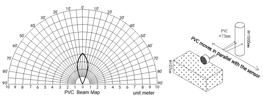
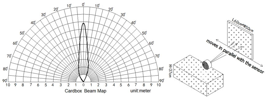
1.5 Effective measurement range Reference beam pattern
1. The tested object is a white cylindrical tube made of PVC, with a height of 100cm and a diameter of 7.5cm.
2. The object to be tested is a "corrugated cardboard box" perpendicular to the central axis of 0 °, and the length * width is 60cm * 50cm.
1.6 Applications
- Horizontal distance measurement
- Liquid level measurement
- Parking management system
- Object proximity and presence detection
- Intelligent trash can management system
- Robot obstacle avoidance
- Automatic control
- Sewer
- Bottom water level monitoring
1.7 Sleep mode and working mode
Deep Sleep Mode: Sensor doesn't have any NB-IoT activate. This mode is used for storage and shipping to save battery life.
Working Mode: In this mode, Sensor will work as NB-IoT Sensor to Join NB-IoT network and send out sensor data to server. Between each sampling/tx/rx periodically, sensor will be in IDLE mode), in IDLE mode, sensor has the same power consumption as Deep Sleep mode.
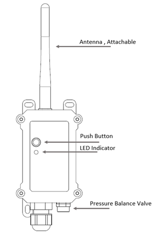
1.8 Button & LEDs
| Behavior on ACT | Function | Action |
|---|---|---|
 1~3s | Send an uplink | If sensor has already attached to NB-IoT/CAT-M1 network, sensor will send an uplink packet, blue led will blink once. |
 >3s | Active Device | Green led will fast blink 5 times. And then start to attach NB-IoT/CAT-M1 network. |
 x5 | Deactivate Device | Red led will solid on for 5 seconds. Means device is in Deep Sleep Mode. |
| x1 | Toggle Serial Communication | Press the ACT button once to activate the serial communication function, and Ready will be displayed in the serial tool. |
Note: When the device is executing a program, the buttons may become invalid. It is best to press the buttons after the device has completed the program execution.
1.9 BLE connection
DDS75-FB support BLE remote configure and firmware update.
BLE can be used to configure the parameter of sensor or see the console output from sensor. BLE will be only activate on below case:
- Press button to send an uplink
- Press button to active device.
- Device Power on or reset.
If there is no activity connection on BLE in 60 seconds, sensor will shut down BLE module to enter low power mode.
1.10 Pin Definitions , Switch & SIM Direction
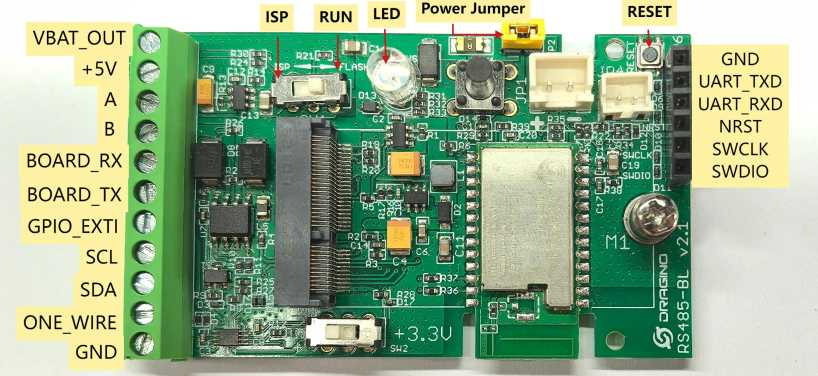
1.10.1 Jumper JP2
Install JP2 to power on the device. Remove it to power off.
1.10.2 BOOT MODE / SW1
The BOOT MODE / SW1 switch has no function on -FB products. Keep it in the FLASH position.
1.10.3 Reset Button
Press to reboot the device.
1.10.4 SIM Card Direction
See this link. How to insert SIM Card.
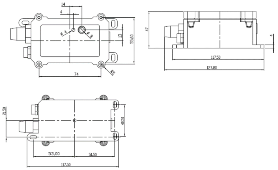
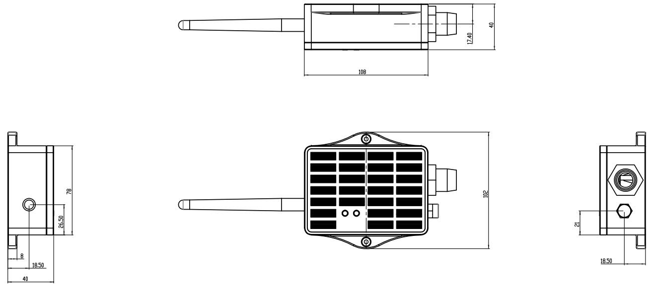
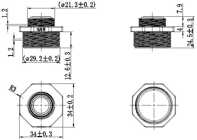
1.11 Mechanical
1.11.1 For FB version
1.11.2 For FS version
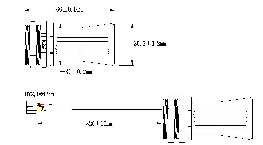
1.11.3 Probe Mechanical
2. Use DDS75-FB to communicate with IoT Server
2.1 Send data to IoT server via NB-IoT/LTE-M network
The DDS75-FB is equipped with a NB-IoT module, the pre-loaded firmware in DDS75-FB will get environment data from sensors and send the value to local NB-IoT network via the NB-IoT module. The NB-IoT network will forward this value to IoT server via the protocol defined by DDS75-FB.
Communication path: DDS75-FB → NB-IoT/LTE-M network → IoT server.
There are two version: -GE and -1T version of DDS75-FB.
GE Version: This version doesn't include SIM card or point to any IoT server. User needs to use AT Commands to configure below two steps to set DDS75-FB send data to IoT server.
-
Install NB-IoT SIM card and configure APN. See Attach Network.
-
Set up sensor to point to IoT Server. See Configure to Connect Different Servers.
Below shows result of different server as a glance.
| Servers | Dash Board | Comments |
|---|---|---|
| Node-Red | 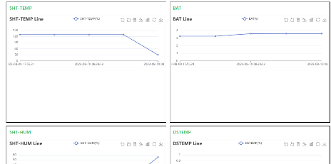 | |
| Tago.IO | ||
| General UDP | Raw Payload. Need Developer to design Dash Board | |
| General MQTT | Raw Payload. Need Developer to design Dash Board | |
| ThingsBoard | 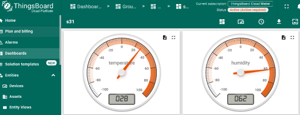 |
1T Version: This version has 1NCE SIM card pre-installed and configure to send value to ThingsEye. User Just need to select the sensor type in ThingsEye and activate the DDS75-FB to view its readings. See here for ThingsEye Config Instruction.
2.2 Payload Types
DDS75-FB uses JSON uplink payloads. Select the transport with AT+PRO:
AT+PRO=2,0: UDP with JSON.AT+PRO=3,0: MQTT with JSON.AT+PRO=4,0: TCP with JSON.
The examples below were captured on DDS75-FB v1.0.8. GPS was disabled in these examples.
2.2.1 Status Packet
After each reactivation, the device sends a status packet once it joins the cellular network and connects to the server.
{
  "IMEI": "355025936334455",
  "Image Version": "v1.0.8",
  "NB-IoT Stack": "NRF9151-001",
  "Model": "DDS75-FB",
  "MCC": "460",
  "MNC": "0",
  "Cell_id": "46134845",
  "Cell_area": "7479",
  "PSM_TAU": "36000",
  "Active_time": "0"
}
| Field | Description |
|---|---|
IMEI | Device International Mobile Equipment Identity. |
Image Version | Device application firmware version. |
NB-IoT Stack | Cellular modem stack identifier. |
Model | Device model reported by the firmware. |
MCC | Mobile Country Code of the serving network. |
MNC | Mobile Network Code of the serving network. |
Cell_id | Serving cell identifier. |
Cell_area | Serving cell's network area code. |
PSM_TAU | Periodic TAU timer (T3412) in seconds. Time the device stays in PSM deep sleep before waking up for a Tracking Area Update (e.g., "36000" = 10 hours). |
Active_time | PSM active timer (T3324) in seconds. How long the modem remains reachable in idle mode before entering deep sleep (e.g., "0" = immediate sleep). |
For the FB-series status query downlink, see Get Stack Version Downlink.
2.2.2 General JSON Format (Type=0)
Example: basic distance measurement with AT+CFGMOD=1 and AT+TDC=600.
{
  "IMEI": "355025936334455",
  "IMSI": "460240275256466",
  "Model": "DDS75-FB",
  "fcnt": "0",
  "signal": "29",
  "bat": 3.63,
  "distance": 1897,
  "DS18B20_Temp": 23.2,
  "count": 0,
  "alarm": "0",
  "i_flag": "0",
  "time": "2026-11-17T03:48:57Z",
  "latitude": 0.000000,
  "longitude": 0.000000,
  "gps_time": "00/00/00,00:00:00",
  "1": ["1896,23.3,2026-11-17T03:14:34Z"],
  "2": ["1894,23.3,2026-11-17T03:27:25Z"],
  "3": ["1896,23.2,2026-11-17T03:29:10Z"],
  "4": ["1896,23.1,2026-11-17T03:32:11Z"],
  "5": ["1896,23.1,2026-11-17T03:33:54Z"],
  "6": ["1894,23.1,2026-11-17T03:41:10Z"],
  "7": ["1895,23.1,2026-11-17T03:44:56Z"],
  "8": ["1897,23.2,2026-11-17T03:48:57Z"]
}
| Field | Type | Description |
|---|---|---|
IMEI | String | Device identifier. |
IMSI | String | Subscriber identifier associated with the SIM. |
Model | String | Device model, "DDS75-FB" |
fcnt | String | Uplink frame counter. |
signal | String | Cellular signal quality. |
bat | Number | Battery voltage in volts. |
distance | Number | Current ultrasonic distance in millimetres. In this example, 1897 means 1897 mm. A disconnected probe can report 0; do not interpret this as a valid zero-distance reading. |
DS18B20_Temp | Number | Current external DS18B20 reading in °C. |
count | Number | External pulse counter value. |
alarm | String | "0" for a normal uplink; "1" for a distance-alarm uplink. |
i_flag | String | "1" for an interrupt-triggered uplink; "0" otherwise. |
time | String | Device timestamp in UTC. The Z suffix denotes UTC. |
latitude, longitude | Number | GPS coordinates in decimal degrees. Both are zero in the GPS-disabled examples. |
gps_time | String | Time of the GPS fix, separate from time. The GPS-disabled placeholder is "00/00/00,00:00:00". |
"1" … "8" | Array | Individual historical entries in the eight-record example. Each array contains one comma-separated string: distance (mm),DS18B20 temperature (°C),sampling time (UTC). |
Use the top-level sensor fields for the current uplink. The numbered samples in the captured payloads are ordered from oldest to newest and each has its own timestamp. In particular, an alarm uplink's top-level time need not match the most recent sample timestamp.
Signal strength (signal):
| Value | Signal strength |
|---|---|
"0" | −113 dBm or less |
"1" | −111 dBm |
"2"–"30" | −109 dBm to −53 dBm |
"31" | −51 dBm or greater |
"99" | Unknown or not detectable |
3. Configure DDS75-FB
3.1 Configure Methods
DDS75-FB supports below configure method:
-
AT Command via Bluetooth Connection (Recommended): BLE Configure Instruction.
-
AT Command via UART Connection : See UART Connecti-on.
3.2 Serial Access Password
After the Bluetooth or UART connection is successful, use the Serial Access Password to unlock AT command access. If UART is inactive, press ACT once and wait for Ready before entering the password.
The label on the box of the node will print the initial password: AT+PIN=xxxxxx, and directly use the six-digit password to access the AT instruction window.
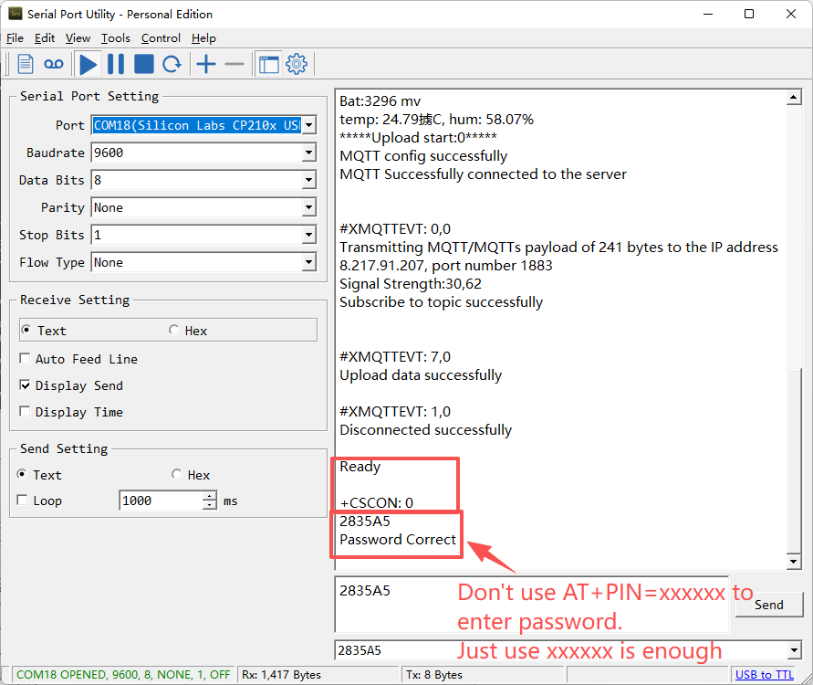
If you need to change the password, use AT+PWORD=xxxxxx (6 characters).
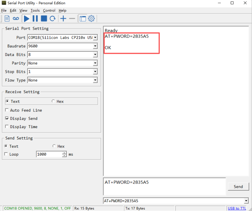
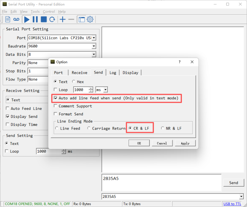
After entering the command, you need to add a line break, and you can also set automatic line breaks in the Bluetooth tool or UART connection tool.
3.3 AT Commands Set
AT?                  // List available commands
AT+<CMD>?            // Get help for a command
AT+<CMD>             // Run a command
AT+<CMD>=<value>     // Set a parameter
AT+<CMD>=?           // Read a parameter
AT+MODEL   : Get module information
ATZ        : Trig a reset of the MCU
AT+CFGMOD  : Working mode selection
AT+DEUI    : Get or set the Device ID
AT+FDR     : Reset Parameters to Factory Default
AT+TDC     : Get or set the application data transmission interval in s
AT+PWORD   : Get or set the System password
AT+CFG     : Print all settings
AT+INTMOD  : Get or Set the trigger interrupt mode (0:input,1:falling or rising,2:falling,3:rising)
AT+APN     : Get or set the APN
AT+AUNAME     : Get or set the APN username
AT+APWD     : Get or set the APN password
AT+SERVADDR: Get or Set the Server address
AT+CLIENT  : Get or Set the MQTT clientID
AT+UNAME   : Get or Set the MQTT Username
AT+PWD     : Get or Set the MQTT password
AT+PUBTOPIC: Get or set MQTT publishing topic
AT+SUBTOPIC: Get or set MQTT subscription topic
AT+5VT     : Get or Set extend the time of 5V power
AT+EXT     : Get or Set Count value
AT+PRO     : Get or Set usage agreement (1:COAP,2:UDP,3:MQTT,4:TCP)
AT+RXDL    : Get or Set the receiving time
AT+ALARM:Get or Set alarm of Distance
AT+GETSENSORVALUE     : Returns the current sensor measurement
AT+TLSMOD  : Get or Set the TLS mode
AT+SLEEP  : Set the sleep mode
AT+MQOS  : Set the QoS level of MQTT
AT+GTIME  : Extend the time to turn on GNSS
AT+QGPS  : Turn off and on GPS
AT+QGTDC     : Get or set GPS positioning interval in units of h
AT+IOTMOD: Configure Network Category to be Searched for under LTE RAT
AT+PDTA: Print the sector data from start page to stop page
AT+PLDTA: Print the last few sets of data
AT+CLRDTA: Clear the storage, record position back to 1st
AT+CLOCKLOG: Get or set the sampling schedule
AT+UDPMOD: Get or set UDP working mode
AT+SFNT: Get or set search for network time
AT+LDATA   : Get the last upload data
AT+REDPT: Get or Set the function of reconnecting the network to send data
AT+DEBUG: Get or Set the debug mode
AT+QCOPS: Get or set operator code
AT+GETLOG : Print serial port logs
AT+UPGRADE  : OTA upgrade.
AT+FREB  : Get or set the number of failed send attempts
3.4 Test Uplink and Change Update Interval
Feature: Change the DDS75-FB transmit interval (unit: seconds).
By default, Sensor will send uplinks every 2 hours.
AT Command: AT+TDC
| Command Example | Function | Response |
|---|---|---|
| AT+TDC=? | Show current transmit Interval | 7200 OK the interval is 7200 seconds |
| AT+TDC=900 | Set Transmit Interval | OK Set transmit interval to 900 seconds |
Downlink Command: 0x01
Format: Command Code (0x01) followed by 3 bytes time value.
- Example 1: Downlink Payload: 01000258 // Set Transmit Interval (TDC) = 600 seconds
- Example 2: Downlink Payload: 01000384 // Set Transmit Interval (TDC) = 900 seconds
3.5 Working Mode and Sensor Wiring
Use AT+CFGMOD=1 for basic ultrasonic distance measurement with an external DS18B20 temperature probe. To switch between external interrupt and pulse counting, use AT+EXT as described in section 3.6, not AT+CFGMOD.
| Peripheral | Wire | Board connection |
|---|---|---|
| Ultrasonic probe | Red / white / yellow / black | 5V / BOARD_RX / BOARD_TX / GND, respectively |
| DS18B20 | Red / yellow / black | VDD / ONE_WIRE / GND, respectively |
| External switch or pulse source | Signal | GPIO_EXTI; see wiring notes in section 3.6 |
For a measurement check, point the probe squarely at a flat target within 280–7500 mm. Run AT+GETSENSORVALUE=0 to sample and request an uplink.
3.6 External Interrupt and Pulse Counting
AT+EXT=a,b sets the counter to a and selects a mode: b=0 for interrupt reporting or b=1 for pulse counting. The defaults are AT+EXT=0,0 and AT+INTMOD=0. Sending AT+EXT=0,1 again resets the counter to zero.
| Command | Trigger on GPIO_EXTI |
|---|---|
AT+INTMOD=0 | Disabled in both modes. |
AT+INTMOD=1 | Rising and falling edges. |
AT+INTMOD=2 | Falling edge. A verified setup connects a switch between GPIO_EXTI and GND; pressing it triggers the interrupt or increments the counter. |
AT+INTMOD=3 | Rising edge. For the rain-gauge application, connect the rain gauge between GPIO_EXTI and GND. |
Interrupt example: Set AT+EXT=0,0 and AT+INTMOD=1. A qualifying edge triggers an uplink with i_flag set to "1".
{
  "IMEI": "355025936334455",
  "IMSI": "460240275256466",
  "Model": "DDS75-FB",
  "fcnt": "2",
  "signal": "20",
  "bat": 3.67,
  "distance": 1896,
  "DS18B20_Temp": 23.2,
  "count": 0,
  "alarm": "0",
  "i_flag": "1",
  "time": "2026-11-17T03:29:10Z",
  "latitude": 0.000000,
  "longitude": 0.000000,
  "gps_time": "00/00/00,00:00:00",
  "1": ["0,23.3,2026-11-17T03:04:16Z"],
  "2": ["0,23.3,2026-11-17T03:04:33Z"],
  "3": ["0,23.3,2026-11-17T03:05:14Z"],
  "4": ["0,23.2,2026-11-17T03:08:55Z"],
  "5": ["1895,23.3,2026-11-17T03:12:25Z"],
  "6": ["1896,23.3,2026-11-17T03:14:34Z"],
  "7": ["1894,23.3,2026-11-17T03:27:25Z"],
  "8": ["1896,23.2,2026-11-17T03:29:10Z"]
}
Counting example: Set AT+EXT=0,1 and AT+INTMOD=1. Qualifying edges increment count. In the following uplink, count is 25 and i_flag is "0".
{
  "IMEI": "355025936334455",
  "IMSI": "460240275256466",
  "Model": "DDS75-FB",
  "fcnt": "2",
  "signal": "24",
  "bat": 3.59,
  "distance": 1896,
  "DS18B20_Temp": 22.7,
  "count": 25,
  "alarm": "0",
  "i_flag": "0",
  "time": "2026-11-17T05:39:11Z",
  "latitude": 0.000000,
  "longitude": 0.000000,
  "gps_time": "00/00/00,00:00:00",
  "1": ["1894,23.1,2026-11-17T03:41:10Z"],
  "2": ["1895,23.1,2026-11-17T03:44:56Z"],
  "3": ["1897,23.2,2026-11-17T03:48:57Z"],
  "4": ["1895,23.2,2026-11-17T03:53:38Z"],
  "5": ["1896,23.2,2026-11-17T03:55:50Z"],
  "6": ["1902,22.6,2026-11-17T05:33:44Z"],
  "7": ["1897,22.7,2026-11-17T05:38:38Z"],
  "8": ["1896,22.7,2026-11-17T05:39:11Z"]
}
3.7 Distance Alarm
Use AT+ALARM=<low>,<high> to configure distance limits in millimetres. A limit of 0 disables that side. Choose useful thresholds within the flat-target measurement range (280–7500 mm).
| Command | Behaviour |
|---|---|
AT+ALARM=0,0 | Disable distance alarms. |
AT+ALARM=500,0 | Lower-limit alarm; tested with a target closer than 500 mm. |
AT+ALARM=0,1500 | Enable only the upper-limit alarm. |
AT+ALARM=500,1500 | Alarm outside the configured window; tested with a target below 500 mm or above 1500 mm. |
An alarm can trigger an immediate uplink without waiting for AT+TDC. The packet carries "alarm":"1".
Lower-limit example: distance=342 mm.
{
  "IMEI": "355025936334455",
  "IMSI": "460240275256466",
  "Model": "DDS75-FB",
  "fcnt": "4",
  "signal": "26",
  "bat": 3.67,
  "distance": 342,
  "DS18B20_Temp": 22.7,
  "count": 0,
  "alarm": "1",
  "i_flag": "0",
  "time": "2026-11-17T10:19:51Z",
  "latitude": 0.000000,
  "longitude": 0.000000,
  "gps_time": "00/00/00,00:00:00",
  "1": ["1900,22.6,2026-11-17T10:13:13Z"],
  "2": ["1900,22.6,2026-11-17T10:13:45Z"],
  "3": ["1899,22.5,2026-11-17T10:14:45Z"],
  "4": ["1899,22.5,2026-11-17T10:15:45Z"],
  "5": ["1899,22.5,2026-11-17T10:16:45Z"],
  "6": ["407,22.5,2026-11-17T10:17:45Z"],
  "7": ["283,22.6,2026-11-17T10:18:45Z"],
  "8": ["342,22.7,2026-11-17T10:19:45Z"]
}
Window example: distance=1899 mm.
{
  "IMEI": "355025936334455",
  "IMSI": "460240275256466",
  "Model": "DDS75-FB",
  "fcnt": "8",
  "signal": "24",
  "bat": 3.66,
  "distance": 1899,
  "DS18B20_Temp": 22.5,
  "count": 0,
  "alarm": "1",
  "i_flag": "0",
  "time": "2026-11-17T10:31:51Z",
  "latitude": 0.000000,
  "longitude": 0.000000,
  "gps_time": "00/00/00,00:00:00",
  "1": ["1896,22.4,2026-11-17T10:24:45Z"],
  "2": ["1899,22.5,2026-11-17T10:25:45Z"],
  "3": ["1895,22.5,2026-11-17T10:26:45Z"],
  "4": ["1897,22.4,2026-11-17T10:27:45Z"],
  "5": ["1894,22.4,2026-11-17T10:28:45Z"],
  "6": ["1899,22.4,2026-11-17T10:29:45Z"],
  "7": ["302,22.5,2026-11-17T10:30:45Z"],
  "8": ["1899,22.5,2026-11-17T10:31:45Z"]
}
JSON downlink (verified):
{"Config":"[AT+ALARM=500,3000]"}
Check the saved limits with AT+ALARM=?.
3.8 Clock Logging
AT+CLOCKLOG=a,b,c,d controls periodic sampling independently of the uplink interval.
| Parameter | Meaning |
|---|---|
a | Logging switch: 0 = disabled; 1 = enabled. |
b | First-sample offset in seconds within the hour, or 65535 to start after joining the network and sending the first packet. |
c | Sampling interval in minutes. |
d | Number of historical samples to include in each periodic uplink. |
Synchronize the device time before enabling clock logging. Set AT+CLOCKLOG=1,65535,1,8 to sample once per minute and include up to eight records per uplink. For example, with AT+TDC=600, the packet is sent at the 10-minute uplink interval, not every time the device samples.
{
  "IMEI": "355025936334455",
  "IMSI": "460240275256466",
  "Model": "DDS75-FB",
  "fcnt": "2",
  "signal": "24",
  "bat": 3.68,
  "distance": 1899,
  "DS18B20_Temp": 22.5,
  "count": 0,
  "alarm": "0",
  "i_flag": "0",
  "time": "2026-11-17T09:23:09Z",
  "latitude": 0.000000,
  "longitude": 0.000000,
  "gps_time": "00/00/00,00:00:00",
  "1": ["1899,22.5,2026-11-17T09:17:03Z"],
  "2": ["1898,22.5,2026-11-17T09:18:03Z"],
  "3": ["1899,22.5,2026-11-17T09:19:03Z"],
  "4": ["1899,22.5,2026-11-17T09:20:03Z"],
  "5": ["1899,22.5,2026-11-17T09:21:03Z"],
  "6": ["1899,22.5,2026-11-17T09:22:03Z"],
  "7": ["1900,22.5,2026-11-17T09:23:03Z"],
  "8": ["1899,22.5,2026-11-17T09:23:09Z"]
}
For remote configuration, send {"Config":"[AT+CLOCKLOG=1,65535,1,8]"} using the FB-series JSON configuration format and verify with AT+CLOCKLOG=?.
3.9 Downlink Configuration
For MQTT, send the downlink to the device's subscribe topic during its receive window after an uplink. Keep Hex command text contiguous, with no spaces or 0x prefix. For JSON and Hex downlink details, see FB Downlink Command Format.
Use JSON Config commands for distance alarms, clock logging and other AT settings where model-specific Hex codes are not confirmed. Verify the resulting setting on the device.
3.10 Network, Transport and GPS Settings
| Setting | AT command example | Description |
|---|---|---|
| Downlink receive window | AT+RXDL=1000 | Set the receive window to 1000 ms. |
| External 5 V supply | AT+5VT=2000 | Extend 5 V power for 2000 ms. |
| MQTT QoS | AT+MQOS=1 | Select MQTT QoS (0–2). |
| TLS authentication | AT+TLSMOD=1,1 | Enable TLS with server authentication. See MQTT over TLS and FB TLS certificate configuration. |
| Cellular network selection | AT+IOTMOD=1,1,2 | Enable LTE-M and NB-IoT, giving priority to NB-IoT. |
| Network search time | AT+SFNT=60 | Set the network search time to 60 seconds. |
| GPS enable | AT+QGPS=1 | Enable GPS; AT+QGPS=0 disables it. |
| GNSS on-time | AT+GTIME | Configure how long GNSS is kept on. |
| GPS positioning interval | AT+QGTDC | Configure the GPS positioning interval in hours. |
The AT+REDPT reconnect-and-resend feature is listed in this firmware. Automatic recovery of all missed reports was not verified in the v1.0.8 test, so do not rely on it as a guarantee against data loss. Use the local history commands below to inspect stored records.
3.11 Reset and Factory Defaults
ATZrestarts the device. For a Hex downlink, send04FFas text.AT+FDRrestores factory parameters. Record the current network and server settings before running it.
3.12 Print last few data entries
Feature: Print the last few data entries
AT command: AT+PLDTA
| Command Example | Response |
|---|---|
| AT+PLDTA=5 Print last 5 entries | 0001 2026/11/5 03:42:20 3480 dist=2209 ds_temp=0.0 alarm:false 0002 2026/11/5 03:43:14 3480 dist=2204 ds_temp=0.0 alarm:false 0003 2026/11/5 03:44:14 3488 dist=2207 ds_temp=0.0 alarm:false 0004 2026/11/5 03:44:20 3480 dist=2209 ds_temp=0.0 alarm:false 0005 2026/11/5 03:45:14 3484 dist=2209 ds_temp=0.0 alarm:false OK |
Downlink Command:
Use the local serial console for this command.
3.13 Print data entries base on page
Feature: Print the sector data from start page to stop page.
AT command: AT+PDTA
| Command Example | Response |
|---|---|
| AT+PDTA=1,1 Print page 1 to 1 | E8000 2026/11/4 15:13:58 3492 dist=2180 ds_temp=0.0 alarm:false E8010 2026/11/4 15:14:58 3492 dist=2180 ds_temp=0.0 alarm:false E8020 2026/11/4 15:15:58 3488 dist=2180 ds_temp=0.0 alarm:false E8030 2026/11/4 15:16:58 3488 dist=2180 ds_temp=0.0 alarm:false E8040 2026/11/4 15:17:58 3480 dist=2180 ds_temp=0.0 alarm:false E8050 2026/11/4 15:18:03 3484 dist=2180 ds_temp=0.0 alarm:false E8060 2026/11/4 15:18:58 3488 dist=2180 ds_temp=0.0 alarm:false E8070 2026/11/4 15:19:58 3492 dist=2180 ds_temp=0.0 alarm:false OK |
Downlink Command:
Use the local serial console for this command.
3.14 Clear Flash Record
Feature: Clear flash storage for data log feature.
AT command: AT+CLRDTA
| Command Example | Function | Response |
|---|---|---|
| AT+CLRDTA | Clear data records | Clear all stored sensor data... Start Tx events OK |
Downlink Command: 0x32
- Send
3200as text. This clears stored records; export any records you need before running it.
3.15 Uplink Logs and Debug Mode
AT+LDATAdisplays the last uplink payload.AT+GETLOGprints serial logs.AT+DEBUG=1keeps the serial port active for troubleshooting. UseAT+DEBUG=0to exit debug mode. Leaving serial communication active increases power consumption.
4. Battery & Power Consumption
DDS75-FB uses an 8500 mAh ER26500 + SPC1520 battery pack. See Battery Information and Power Consumption for battery handling and replacement.
5. Firmware Update
Use the Dragino Cellular Firmware Repository to locate the DDS75-FB firmware and review its changelog. Use only a firmware file listed for the product you are updating.
5.1 Over-the-Air (OTA) Firmware Update via HTTP
See OTA Upgrade for NB-IoT/LTE-M End Nodes.
- Copy the full HTTP URL of the DDS75-FB
.binfile for the desired version. - Connect via BLE or UART and unlock AT access. Send
AT+UPGRADE="<firmware-url>", replacing the placeholder with the copied URL. - Alternatively, use a server downlink with the following JSON format. Replace the placeholder with the same URL.
{"Config":"[AT+UPGRADE=\"<firmware-url>\"]"}
Keep power connected during the update. After reboot, verify the firmware version in a status packet or with AT+MODEL.
5.2 Firmware Update through UART TTL
Download the DDS75-FB firmware file and follow UART Upgrade for -FB/-FS/-FE Models.
6. FAQ
6.1 How can I access the NRF9151-NGFF AT Commands?
User can access to NRF9151-NGFF directly and send AT Commands.
See NRF9151-NGFF AT Command set
6.2 Can I use DDS75-FB in condensation environment?
DDS75-FB is not suitable to be used in condensation environment. Condensation on the DDS75-FB probe will affect the reading and always got 0.
6.3 General Manual for -FB , -FS models
Users can follow the instructions in this link to see how to configure to connect to different servers.
6.4 Why does the sensor reading show 0 or "No sensor"?
-
The target is in the blind zone (less than 280 mm for a flat target). Move it within the rated range.
-
The probe is disconnected or incorrectly wired. Check the wires listed in section 3.5.
-
The platform is using the wrong decoder. Read the numeric
distancefield from the DDS75-FB JSON payload.
6.5 Why is there no LED response when I press the button on the solar panel model?
If the LED does not light up when you press the button, it may be because the battery has entered protection mode.
Solution: To reactivate the battery, simply expose the solar panel to direct sunlight. For more details, please refer to: Battery Protection State (Apply to Solar Panel + Li-ion battery)
6.6 Does this device support GPS positioning?
Yes. This device supports GPS function and can report latitude and longitude coordinates in the uplink payload.
For configuration and usage details, please refer to: Add Location Data on Uplink Packet
7. Order Info
Part Number: DDS75-FB-XX
XX:
-
GE: General version ( Exclude SIM card)
-
1T: with 1NCE* 10 years 500MB SIM card and Pre-configure to ThingsEye server
8. Packing Info
Package Includes:
-
DDS75-FB NB-IoT/LTE-M Distance Detection sensor x 1
-
External antenna x 1
Dimension and weight:
See section 1.11 for mechanical drawings. Package dimensions and weights are not specified here.
9. Support
-
Support is provided Monday to Friday, from 09:00 to 18:00 GMT+8. Due to different timezones we cannot offer live support. However, your questions will be answered as soon as possible in the before-mentioned schedule.
-
Provide as much information as possible regarding your enquiry (product models, accurately describe your problem and steps to replicate it etc) and send a mail to Support@dragino.cc.