SN50V3-MS General-Purpose Mesh Node
1. Introduction
1.1 What is the SN50V3-MS General-Purpose Mesh Node?
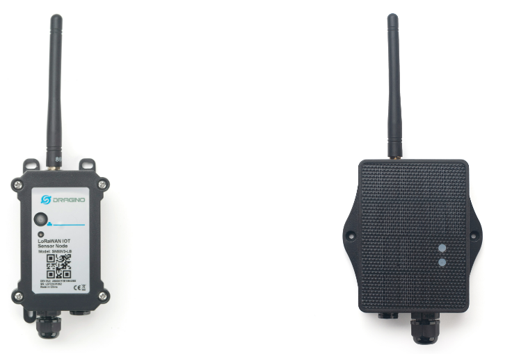
SN50V3-MS is a Dragino general-purpose Mesh Node for outdoor IoT applications requiring long range, low power consumption, and multi-hop coverage.
The standard SN50V3-MS reports its battery and operating status and is not configured for a specific external sensor. Its hardware provides multiple I/O resources that can be used with model-specific firmware to connect supported sensors or external devices.
1.2 Features
- LoRa Mesh communication with multi-hop relaying between nodes.
- STM32WLE5 low-power wireless MCU.
- S-type outdoor enclosure, solar panel, and 3000 mAh rechargeable lithium battery.
- Battery voltage, battery level, and operating-status reporting.
- Digital I/O, UART, I2C, OneWire, and controlled power-output resources.
- Firmware upgrades through USB serial or PC BLE.
- Automatic scheduled reporting followed by low-power sleep.
1.3 Specifications
Common DC characteristics
| Item | Specification |
|---|---|
| Main unit operating voltage | Approximately 2.5 V to 3.6 V |
| Main unit operating temperature | -40 °C to 85 °C; battery operating temperature is subject to the battery specification |
I/O interfaces
| Hardware resource | Description |
|---|---|
| BAT output | Connected directly to the battery; voltage varies with battery condition, approximately 2.6 V to 3.6 V |
| Controlled 5 V output | Provides a controlled power supply for an external sensor |
| Digital I/O | Up to 3 interrupt or digital input/output hardware resources |
| OneWire | Up to 3 OneWire hardware resources |
| UART | 1 external UART hardware resource |
| I2C | 1 external I2C hardware resource |
The I/O resources are multiplexed. Their usable combination depends on the installed firmware and target sensor.
Mesh main unit
| Item | Specification |
|---|---|
| MCU | STM32WLE5, 48 MHz ARM Cortex-M4 |
| Flash | 256 KB |
| RAM | 64 KB |
| Radio | STM32WLE5 integrated sub-GHz LoRa radio |
| Power supply | Solar panel + 3000 mAh rechargeable lithium battery |
| Local interfaces | 3.3 V UART, BLE |
| Antenna | Sub-GHz LoRa antenna matching the shipping Region |
1.4 Applications
- Remote device access for agriculture, parks, and outdoor facilities.
- Low-power monitoring projects where site power and cabling are difficult.
- Areas requiring relaying through other Mesh Nodes.
- Custom projects using digital inputs, serial interfaces, I2C, or OneWire devices.
- Long-term outdoor deployments requiring solar power.
1.5 Sleep Mode and Working Mode
In the sleep state, the node disables most functions and remains in low-power standby until its next scheduled wake-up or a user action wakes it.
After enrollment, the standard working cycle is:
Reach scheduled time -> Wake up -> Prepare device or supported sensor data
                     -> Send data to the Mesh gateway
                     -> Wait for a short communication window -> Sleep
A device with sensor-specific firmware powers, reads, and reports its supported sensor during the active cycle.
1.6 Button Operations and LED Status
Button operations and LED indications are common to Dragino Mesh Nodes. See 3.1 Button Operations and LED Status in the Mesh Quick Start for everyday operations. For factory reset, manual sleep, and Bootloader entry, see How to Use Advanced Button Operations.
1.7 BLE and Local Interfaces
SN50V3-MS provides 3.3 V UART and BLE local interfaces. BLE can be used for normal APP firmware updates from a PC through PC BLE in FirmwareUpdateUtility.
The mobile upgrade workflow is still under development.
1.8 Pin, Enclosure, and Mechanical Reference
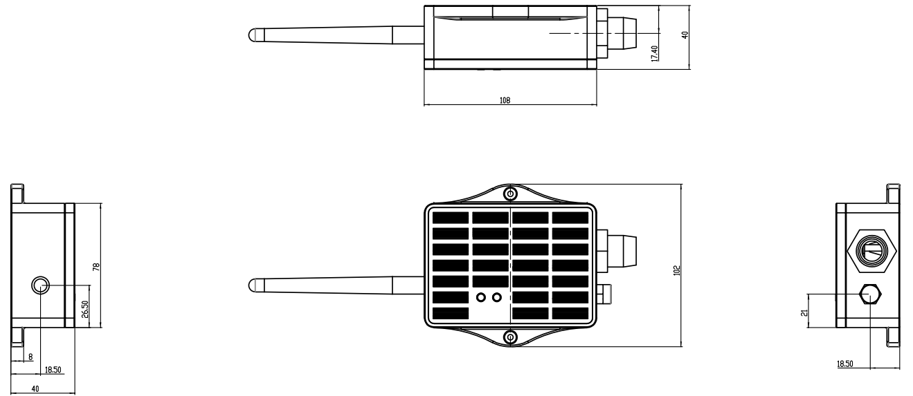
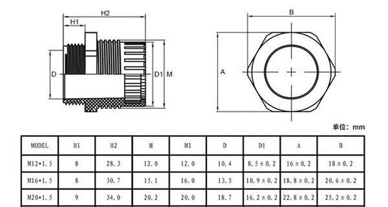
The following figures show the LA66S Mesh module pin definitions, solar enclosure dimensions, mounting points, cable outlets, and cable-gland size options used by SN50V3-MS.
Pin definitions
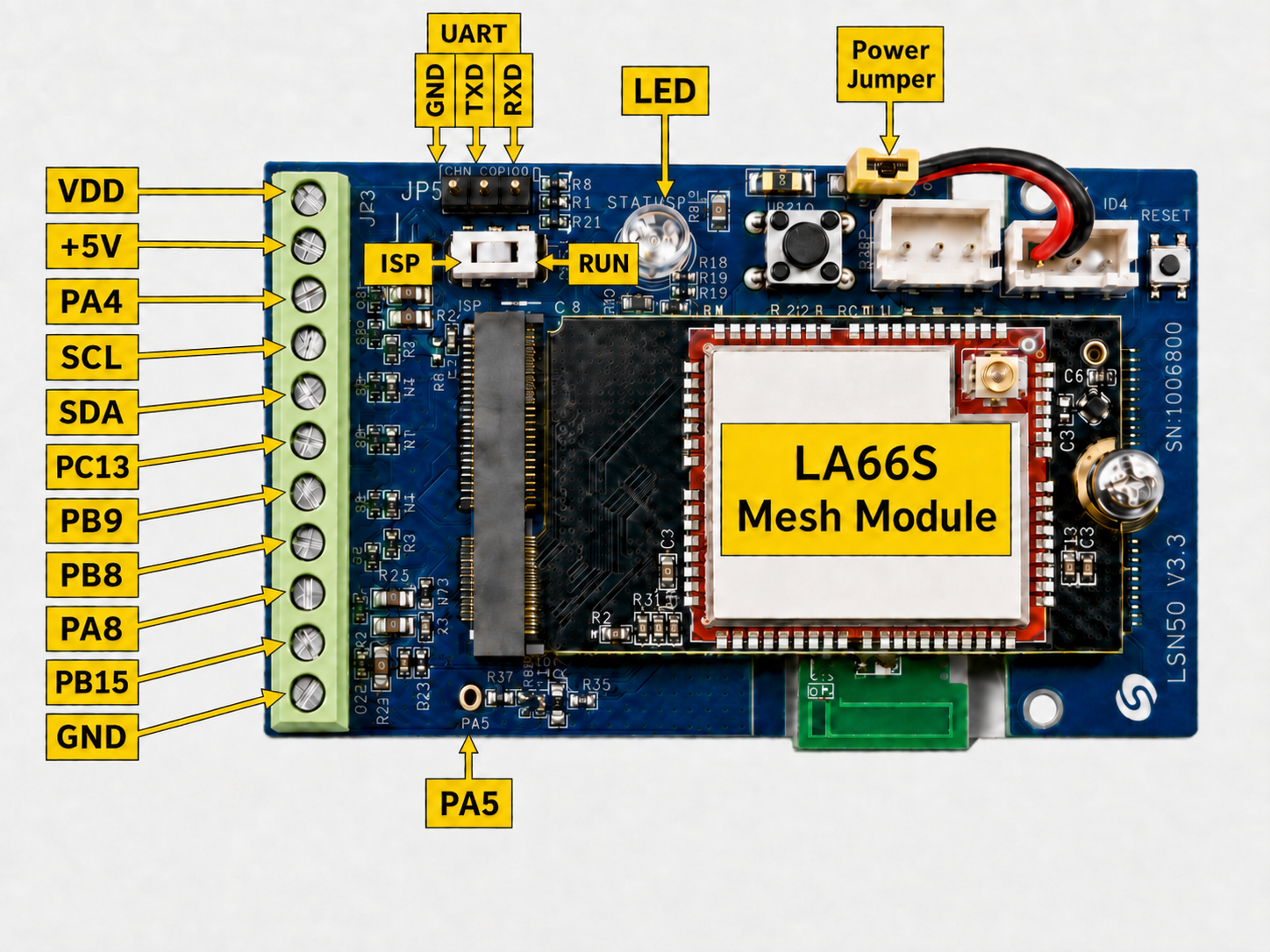
On the LSN50V3 base board, some silkscreen pin names differ from the STM32 pin names used in firmware. See How Board Pins Map to STM32 Pins Used in Firmware.
Solar enclosure dimensions and mounting reference
Cable-gland dimensions and size options
1.9 External-Device Compatibility
Wiring an external sensor does not automatically produce sensor data. The installed SN50V3-MS firmware and Mesh gateway must support the target sensor and its fields.
Before connecting an external device, confirm its supply voltage, peak and standby current, polarity, signal levels, wiring, interface requirements, firmware support, and expected gateway fields.
Check the following:
- The external device meets the electrical requirements of the selected interface.
- The installed firmware supports the sensor or device.
- The selected I/O resources are available in that firmware.
- Outdoor wiring has suitable waterproofing and insulation.
- The external device's power consumption is suitable for the site's solar and battery conditions.
1.10 Installation
Use a cable gland that matches the external cable diameter. Keep unused cable openings sealed and install the enclosure with its cable outlets facing downward. Provide a drip loop so water does not run along a cable toward the enclosure.
After wiring an external device, test it above ground. Confirm that the sensor powers correctly, the node remains online, and the expected fields appear on the Mesh gateway before sealing the enclosure and completing the field installation.
2. Mesh Operation
2.1 How It Works
The node can communicate directly with a Mesh gateway or relay its data through other awake Mesh Nodes.
The standard SN50V3-MS sends:
- Battery level.
- Battery voltage.
- Device online and operating status.
- Data update time.
The standard model has no fixed external-sensor data. When sensor-specific firmware is installed, the node collects and sends the corresponding supported fields.
2.2 Product-Specific Verification
Complete the general enrollment and first-report procedure in the Mesh Quick
Start before final installation.
Because SN50V3-MS behavior depends on the installed firmware, verify
compatibility before connecting or sealing any external device.
| Stage | Verify | Expected result |
|---|---|---|
| Firmware and interface | Supported external device, firmware profile, I/O resources, and electrical requirements | The selected firmware supports the device and the interface is used within its voltage and current limits |
| Above-ground test | Sensor power, signal behavior, and the node's operating stability | The external device works without resetting the node, and the expected sensor fields are available |
| Mesh data | Battery, operating status, and any sensor-specific fields | The received fields match the installed firmware and the connected device |
| Final installation | Cable gland, unused openings, enclosure sealing, and a report after mounting | The external device remains functional and the enclosure is protected from water and cable strain |
2.3 Mesh Payload
SN50V3-MS sends its business payload to the Mesh gateway on Mesh application port 290. Port 287 is used for configuration and administration messages and is not part of this payload.
The common 14-byte header is documented in 2.4 Mesh Business Data. This section defines the DATA layouts for SN50V3-MS.
Shared DATA prefix
The four MOD profiles start with the same 9-byte DATA prefix. Profile-specific sensor fields begin at DATA offset 9.
DATA offset | Field | Format | Description |
|---|---|---|---|
| 0–1 | battery_mv | uint16 LE | Battery voltage in mV; 0 = invalid |
| 2 | battery_percent | uint8 | Battery level 0–100; 0xFF = invalid |
| 3 | report_reason | uint8 | Reason bit mask |
| 4–5 | valid_mask | uint16 LE | Sensor validity bit mask |
| 6 | state_mask | uint8 | Current digital-input states |
| 7 | trigger_mask | uint8 | Inputs that triggered this report |
| 8 | overflow_mask | uint8 | Event-counter overflow flags |
The mask values are:
- Report reason:
0x01periodic,0x02sensor event,0x04manual,0x08gateway request,0x10factory, and0x80unknown. - Valid sensors:
0x0001DS18B20 #1,0x0002DS18B20 #2,0x0004DS18B20 #3, and0x0008SHT3x. - Digital inputs:
0x01PB3,0x02PB4, and0x04PB15. These values apply tostate_mask,trigger_mask, andoverflow_mask.
Profile summary
| Profile | data_type | DATA size | Total size |
|---|---|---|---|
| Base | 0x00 | 3 | 17 |
| MOD1 | 0x10 | 21 | 35 |
| MOD2 | 0x11 | 21 | 35 |
| MOD3 | 0x12 | 17 | 31 |
| MOD4 | 0x13 | 25 | 39 |
The Base profile contains only battery voltage and battery percentage. The four MOD profiles use the shared prefix above followed by these profile-specific fields:
| Field | MOD1 | MOD2 | MOD3 | MOD4 | Format |
|---|---|---|---|---|---|
| DS18B20 #1 | 9–10 | 9–10 | 9–10 | 9–10 | int16 LE / 16 °C |
| DS18B20 #2 | — | 11–12 | — | — | int16 LE / 16 °C |
| DS18B20 #3 | — | 13–14 | — | — | int16 LE / 16 °C |
| ADC | 11–12 | 15–16 | 11–12 | 11–12 | Filtered 12-bit value |
| SHT3x temperature | 13–14 | — | — | — | int16 LE / 10 °C |
| SHT3x humidity | 15–16 | — | — | — | uint16 LE / 10 % RH |
| PB3 event sequence | 17–20 | 17–20 | — | 13–16 | uint32 LE |
| Pulse count | — | — | 13–16 | — | uint32 LE |
| PB4 event sequence | — | — | — | 17–20 | uint32 LE |
| PB15 event sequence | — | — | — | 21–24 | uint32 LE |
In MOD4, battery measurement is unavailable because the external ADC uses the battery-measurement input. The payload therefore uses battery_mv = 0 and battery_percent = 0xFF.
3. Configure SN50V3-MS
3.1 Configuration Method
Common Mesh configuration is managed through the Mesh gateway. Use the Mesh Quick Start for the current configuration and enrollment workflow.
Product-specific behavior depends on the installed firmware and supported external sensor.
3.2 Region and Radio Parameters
Each unit ships with a fixed Region and LoRa parameters set during manufacturing. The Mesh gateway and node must use the same Region.
3.3 Scheduled and Manual Reporting
After enrollment, the node follows the wake-up and reporting schedule provided by the Mesh gateway.
To request an immediate update:
- Wake the node if it is sleeping.
- While it is active, hold the button and release it within 1 to 3 seconds.
- Allow the supported device or sensor operation to finish.
- Confirm that the new data and update time appear on the Mesh gateway.
4. Battery & Power Consumption
Battery performance depends on the reporting interval, Mesh coverage, relay conditions, external-sensor operating and standby current, sunlight, solar-panel orientation, ambient temperature, and battery condition.
Short reporting intervals, long active periods, or high-power external devices increase power consumption. SN50V3-MS uses a solar panel and a 3000 mAh rechargeable lithium battery.
Battery Info & Power Consumption Analyze.
5. Firmware Update
Use only APP firmware built for SN50V3-MS, the intended external-sensor support, and the device's shipping Region.
For the firmware preparation and upload procedure, see 2. How to upload the firmware.
The mobile upgrade feature is still under development.
6. FAQ
6.1 Can any external sensor be connected to SN50V3-MS?
No. The sensor must meet the electrical requirements of an available interface, and the installed firmware and Mesh gateway must support that sensor. Complete the checks in Section 1.9 before connecting it.
6.2 Why does the node report battery data but no external-sensor data?
The standard SN50V3-MS is not configured for a specific external sensor. Confirm that the installed firmware supports the connected sensor and that the gateway supports its fields.
6.3 Why does the node reset or become unstable after a sensor is connected?
Disconnect the sensor and check its supply voltage, peak current, polarity, signal levels, wiring, and selected I/O resources before reconnecting it.
6.4 How should an outdoor installation be maintained?
- Inspect the antenna, enclosure mounting, cable glands, wiring, insulation, and drip loop.
- Keep the solar panel clean and unobstructed.
- Check for moisture or corrosion inside the enclosure.
- When replacing an external sensor, repeat the compatibility and above-ground verification before resealing the enclosure.
For enrollment, Region, gateway connectivity, general power, or firmware-update questions, see the general Mesh FAQ.
7. Order Info
Ordering details and Region-specific part numbers for SN50V3-MS will be added when the product options are finalized.
8. Packing Info
Package contents, cable-hole options, dimensions, and weights for SN50V3-MS will be added in a future documentation update.
9. Support
Dragino support is available Monday to Friday from 09:00 to 18:00 GMT+8. When requesting assistance, provide the product model, firmware identification, connected sensor, wiring information, Region, and the steps required to reproduce the problem.
Contact: Support@dragino.cc