LMS01-MS Leaf Moisture and Temperature Mesh Node
1. Introduction
1.1 What is the Dragino Mesh Leaf Moisture Sensor?
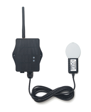
LMS01-MS is a Dragino Mesh Node for monitoring leaf-surface moisture and temperature. Its artificial leaf-shaped sensor uses a frequency-domain dielectric measurement method to detect changes caused by liquid droplets on the sensing surface.
The sensor converts the covered portion of its surface into a leaf-moisture percentage. It represents the wetting conditions experienced by nearby crop leaves rather than the plant's internal water content.
LMS01-MS sends data to a Dragino Mesh gateway directly or through other Mesh Nodes.
1.2 Features
- Leaf-surface moisture measurement from
0 to 100 %. - Leaf-sensor temperature measurement.
- Frequency-domain dielectric measurement method.
- Artificial leaf shape with approximately 15 vein lines per centimeter.
- IP67 sensor for outdoor crop monitoring.
- Standard
3.5 msensor cable. - LoRa Mesh communication with multi-hop relaying.
- Solar panel and 3000 mAh rechargeable lithium battery.
- Mesh reporting and gateway decoding currently under development.
1.3 Specifications
Common DC characteristics
| Item | Specification |
|---|---|
| Main unit operating voltage | Approximately 2.5 V to 3.6 V |
| Main unit operating temperature | -40 °C to 85 °C; battery operating temperature is subject to the battery specification |
Leaf moisture
| Item | Specification |
|---|---|
| Range | 0 to 100 % |
| Resolution | 0.1 % |
| Accuracy | ±3 % from 0 to 50 %; ±6 % above 50 % |
| Measurement information | Proportion of the sensing surface covered by liquid droplets |
Leaf temperature
| Item | Specification |
|---|---|
| Range | -50 °C to 80 °C |
| Resolution | 0.1 °C |
| Accuracy | ±0.5 °C from -10 °C to 70 °C; ±1.0 °C outside this range |
Leaf sensor
| Item | Specification |
|---|---|
| Operating voltage | 5 V to 24 V; maximum 26.7 V |
| Current while powered | Peak less than 30 mA; average less than 10 mA |
| Response time | Less than 1 second |
| Measurement stabilization time | Approximately 2 seconds |
| Communication | RS-485 or UART using Modbus RTU |
| Protection rating | IP67 |
| Operating temperature | -40 °C to 85 °C |
| Cable length | Standard 3.5 m, UL2464 5-core cable |
Mesh main unit
| Item | Specification |
|---|---|
| Radio | Sub-GHz LoRa radio for Dragino Mesh communication |
| Power supply | Solar panel + 3000 mAh rechargeable lithium battery |
| Local interfaces | 3.3 V UART, BLE |
| Antenna | Sub-GHz LoRa antenna matching the shipping Region |
1.4 Applications
- Monitoring leaf wetness after irrigation, spraying, rainfall, or dew formation.
- Comparing drying time between crop areas or greenhouse zones.
- Observing conditions associated with foliar fertilizer application.
- Detecting surface conditions related to dew and frost.
- Monitoring cutting-propagation environments.
- Remote agricultural sites requiring solar power and multi-hop wireless coverage.
1.5 Sleep Mode and Working Mode
In the sleep state, the node disables most functions and remains in low-power standby until its next scheduled wake-up or a user action wakes it.
The intended working cycle is:
Reach scheduled time -> Wake up -> Power and read the leaf sensor
                     -> Validate and send the measurement
                     -> Wait for a short communication window -> Sleep
The final scheduled reporting behavior will be confirmed with the production firmware.
1.6 Button Operations and LED Status
Button operations and LED indications are common to Dragino Mesh Nodes. See 3.1 Button Operations and LED Status in the Mesh Quick Start for everyday operations. For factory reset, manual sleep, and Bootloader entry, see How to Use Advanced Button Operations.
1.7 BLE and Local Interfaces
LMS01-MS provides 3.3 V UART and BLE local interfaces. BLE is intended for normal APP firmware updates from a PC through PC BLE in FirmwareUpdateUtility when compatible LMS01-MS firmware is available.
The mobile upgrade workflow is still under development.
1.8 Enclosure and Mechanical Reference
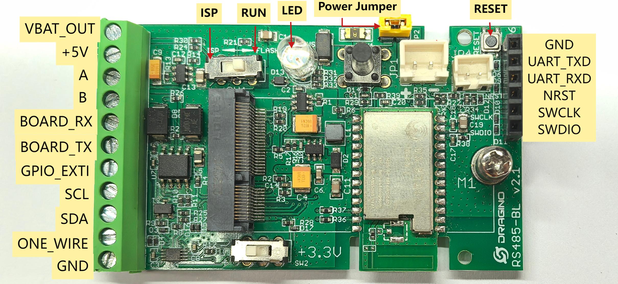
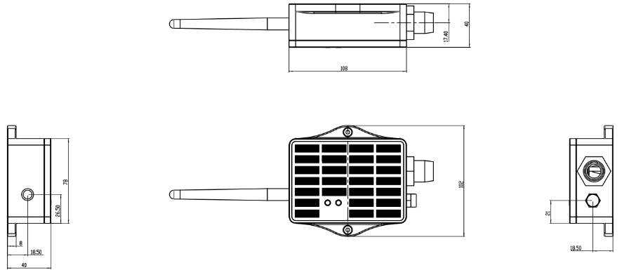
The following figures show the pin definitions and the solar enclosure dimensions, mounting points, and cable outlets used by LMS01-MS.
Pin definitions
Solar enclosure dimensions and mounting reference
1.9 Understanding Leaf Moisture and Temperature
Leaf moisture represents the percentage of the artificial sensing surface covered by liquid droplets. It does not measure moisture inside a real leaf or the plant's internal water status.
The reading can change with:
- droplet size and distribution;
- rain, dew, irrigation, or spray exposure;
- sensor tilt and orientation;
- sheltering by nearby leaves or structures;
- evaporation and airflow;
- contamination or material covering the sensing surface.
Leaf-sensor temperature is measured at the artificial leaf. Direct sunlight, shading, airflow, and recent wetting can cause it to differ from ambient-air temperature or the temperature of a nearby natural leaf.
For comparisons, install sensors at similar heights, angles, orientations, and levels of crop exposure. Establish project thresholds from observations at the deployment site.
1.10 Installation
1.10.1 Identify the Sensing Surface
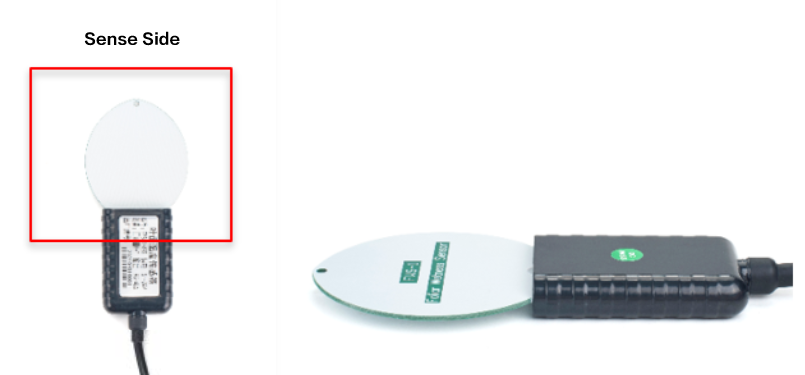
The leaf-shaped sensor has two sides. The side without printed words is the sensing side and must face the exposure being monitored.
1.10.2 Select a Representative Position
Place the sensor beside the crop at a height and exposure representative of the leaves being monitored. Use a consistent position relative to the crop canopy when comparing zones.
Avoid a position unintentionally shielded from irrigation, spray, rain, or dew when those conditions are the subject of measurement.
1.10.3 Mount the Sensor
- Orient the sensing side toward the exposure being monitored.
- Match the tilt angle and orientation of nearby crop leaves as closely as practical.
- Secure the sensor with non-metallic wire or another non-metallic support.
- Keep the sensing surface uncovered.
- Route the cable without tension, crushing, or sharp bends.
- Install the enclosure above ground with the cable outlet facing downward and provide a drip loop.
- Place the solar panel where it receives stable, unobstructed sunlight.
1.10.4 Installation Check
Confirm that:
- the sensing side faces the intended exposure;
- the sensor angle represents the nearby crop leaves;
- the support does not cover the sensing surface;
- the sensor and cable are secure without mechanical tension;
- the enclosure connection is protected from water running along the cable.
When Mesh reporting becomes available, confirm that leaf-moisture and temperature values appear and follow the wetting and drying conditions observed at the installation.
2. Mesh Operation
2.1 How It Works
Mesh reporting and gateway decoding for LMS01-MS are currently under development. When enabled, the Mesh gateway is expected to present:
- Leaf-surface moisture in
%. - Leaf-sensor temperature in
°C. - Battery level or battery status.
- Device online status and data update time.
The exact field names and gateway layout will be finalized with the production firmware and decoder.
2.2 Product-Specific Verification
Complete the general enrollment and first-report procedure in the Mesh Quick Start before final installation. The product-specific checks below focus on sensor orientation and exposure.
| Stage | Verify | Expected result |
|---|---|---|
| Sensing surface | The side without printed words faces the monitored exposure | The sensing surface is exposed to the rain, dew, irrigation, or spray conditions being studied |
| Position and support | Height, angle, orientation, support, and crop exposure | The artificial leaf represents the nearby crop leaves without the support covering its surface |
| Initial observation | Wetting and drying behavior after the sensor is positioned | Leaf-moisture changes follow the observed site conditions; leaf-sensor temperature is interpreted as the temperature of the artificial leaf |
| Final installation | Cable routing, enclosure orientation, and drip loop | The sensor remains secure, the cable is not under tension, and the sensing surface remains uncovered |
2.3 Mesh Payload
LMS01-MS sends its business payload to the Mesh gateway on Mesh application port 290. Port 287 is used for configuration and administration messages and is not part of this sensor payload.
The common 14-byte header is documented in 2.4 Mesh Business Data. This section defines the DATA block for LMS01-MS.
LMS01-MS uses data_type = 0x05. The DATA block is 7 bytes, so the complete payload is 21 bytes. Multi-byte values are little-endian.
The Mesh payload always stores leaf moisture and leaf temperature in hundredths, even when the probe is configured to return tenths.
DATA Structure
DATA offset | Field | Format | Interpretation |
|---|---|---|---|
| 0–1 | battery_mv | uint16 LE | Battery voltage in mV; 0 = invalid |
| 2 | battery_percent | uint8 | Battery level 0–100; 0xFF = invalid |
| 3–4 | leaf_moisture_x100 | uint16 LE | Raw value / 100 = %; 65535 = invalid |
| 5–6 | leaf_temperature_c_x100 | int16 LE | Raw value / 100 = °C; 32767 = invalid |
3. Configure LMS01-MS
3.1 Configuration Method
Common Mesh configuration is managed through the Mesh gateway. Use the Mesh Quick Start for the current configuration and enrollment workflow.
3.2 Region and Radio Parameters
Each unit ships with a fixed Region and LoRa parameters set during manufacturing. The Mesh gateway and node must use the same Region.
3.3 Scheduled and Manual Reporting
The final scheduled Mesh reporting and manual-report behavior for LMS01-MS are currently under development. This section will be updated when the production firmware workflow is available.
4. Battery & Power Consumption
Battery performance depends on the reporting interval, Mesh coverage, relay conditions, sunlight, solar-panel orientation, ambient temperature, sensor power-up duration, and battery condition.
LMS01-MS uses a solar panel and a 3000 mAh rechargeable lithium battery.
Battery Info & Power Consumption Analyze.
5. Firmware Update
Use only an APP image released for LMS01-MS and the device's shipping Region.
When compatible firmware is available, follow 2. How to upload the firmware.
The mobile upgrade feature is still under development.
6. FAQ
6.1 What does the leaf-moisture percentage represent?
It represents the portion of the artificial sensing surface covered by liquid droplets. It does not measure moisture inside a real leaf or the plant's internal water status.
6.2 Why does the reading not match nearby crop leaves?
Check sensor height, angle, orientation, crop exposure, shielding, and droplet distribution. The artificial leaf should be installed in a position representative of the crop leaves being monitored.
6.3 Why does moisture remain at zero or stay high after drying?
For a zero reading on a wet sensor, confirm that water reached the sensing side without printed words and check the cable. For a persistently high reading, inspect the surface for retained water, residue, or material that prevents normal drainage.
6.4 How should LMS01-MS be maintained?
- Keep the solar panel clean and unobstructed.
- Inspect the antenna, enclosure, connectors, cable, and drip loop.
- Confirm that the support remains secure and does not cover the sensing surface.
- Check that the sensor still matches the intended crop height, angle, orientation, and exposure.
- Do not scratch, paint, coat, or permanently cover the sensing surface.
- Repeat the installation check after moving or reinstalling the sensor.
For enrollment, Region, gateway connectivity, general power, or firmware-update questions, see the general Mesh FAQ.
7. Order Info
Ordering details and Region-specific part numbers for LMS01-MS will be added when the product options are finalized.
8. Packing Info
Package contents, dimensions, and weights for LMS01-MS will be added in a future documentation update.
9. Support
Dragino support is available Monday to Friday from 09:00 to 18:00 GMT+8. When requesting assistance, provide the product model, firmware identification, Region, sensor orientation, installation conditions, and the steps required to reproduce the problem.
Contact: Support@dragino.cc