DDS75-MS Ultrasonic Distance Mesh Node
1. Introduction
1.1 What is the DDS75-MS Ultrasonic Distance Mesh Node?
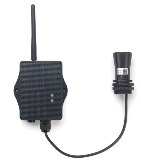
DDS75-MS is a Dragino Mesh Node for measuring the distance between an ultrasonic sensor and a flat or reflective object. The sensor reports processed distance values over an RS485 interface and can send them directly to a Mesh gateway or through other awake Mesh Nodes.
The node supports a normal measurement mode and a delta monitoring mode. Normal mode reports one distance result during each full reporting cycle. Delta mode performs low-power monitoring samples between full cycles and creates an event record when the measured distance changes by more than the configured threshold.
1.2 Features
- Ultrasonic distance measurement through an RS485 Modbus RTU sensor.
- Measurement range from
280 mmto7500 mmfor a valid processed distance. - Normal mode for scheduled distance reporting.
- Delta mode for threshold monitoring and burst event reporting.
- Configurable auxiliary sample interval, change threshold, and event sample count.
- Explicit Valid, No sensor, and Invalid measurement statuses.
- Direct or multi-hop Mesh communication.
- Solar panel and
3000 mAhrechargeable lithium battery. - Scheduled reporting and low-power sleep operation.
- Configuration through Mesh port
295. - Firmware updates through USB serial or PC BLE.
1.3 Specifications
Distance sensor
| Item | Specification |
|---|---|
| Measurement principle | Ultrasonic distance detection |
| Valid processed distance | 280 mm to 7500 mm |
| Accuracy | ±(10 mm + 0.3% of distance) |
| Measurement angle | Approximately 40° |
| Sensor interface | RS485 Modbus RTU |
| Sensor address | 0x01 |
| UART settings | 9600 8N1 |
| Sensor cable length | Approximately 320 mm |
Mesh main unit
| Item | Specification |
|---|---|
| MCU | STM32WLE5, 48 MHz ARM Cortex-M4 |
| Flash | 256 KB |
| RAM | 64 KB |
| Radio | Integrated sub-GHz LoRa radio |
| Power supply | Solar panel + 3000 mAh rechargeable lithium battery |
| Main unit operating voltage | Approximately 2.5 V to 3.6 V |
| Operating temperature | -40 °C to 85 °C for the main unit |
| Local interfaces | 3.3 V UART, BLE |
| Enclosure protection | IP66 |
| Antenna | Sub-GHz LoRa antenna matching the shipping Region |
1.4 Applications
- Horizontal distance measurement.
- Liquid level and tank monitoring.
- Parking space and object presence detection.
- Intelligent waste-bin monitoring.
- Robot obstacle detection.
- Sewer and water-level monitoring.
- Industrial or outdoor automation requiring low-power distance monitoring.
1.5 Sleep Mode and Working Mode
In sleep mode, the node disables the sensor interface and Mesh runtime functions until the next scheduled wake-up, a user action, or a supported delta monitoring wake-up.
Normal mode performs one full measurement cycle:
Scheduled wake -> Power the sensor and RS485 interface
               -> Wait for sensor warm-up
               -> Read and validate the distance
               -> Send the result to the Mesh gateway
               -> Wait for the communication window -> Sleep
Delta mode adds sensor-only monitoring samples between full reporting cycles. The auxiliary wake reads the sensor without starting the complete Mesh runtime. When the absolute change from the active baseline is greater than the configured threshold, the node captures the configured burst and requests a full wake to publish the delta event.
1.6 Button Operations and LED Status
Button operations and LED indications are common to Dragino Mesh Nodes. See 3.1 Button Operations and LED Status in the Mesh Quick Start for everyday operations. For factory reset, manual sleep, and Bootloader entry, see How to Use Advanced Button Operations.
1.7 BLE and Local Interfaces
DDS75-MS provides 3.3 V UART and BLE local interfaces. BLE can be used for normal APP firmware updates from a PC through PC BLE in FirmwareUpdateUtility.
The mobile upgrade workflow is still under development.
1.8 Enclosure and Mechanical Reference
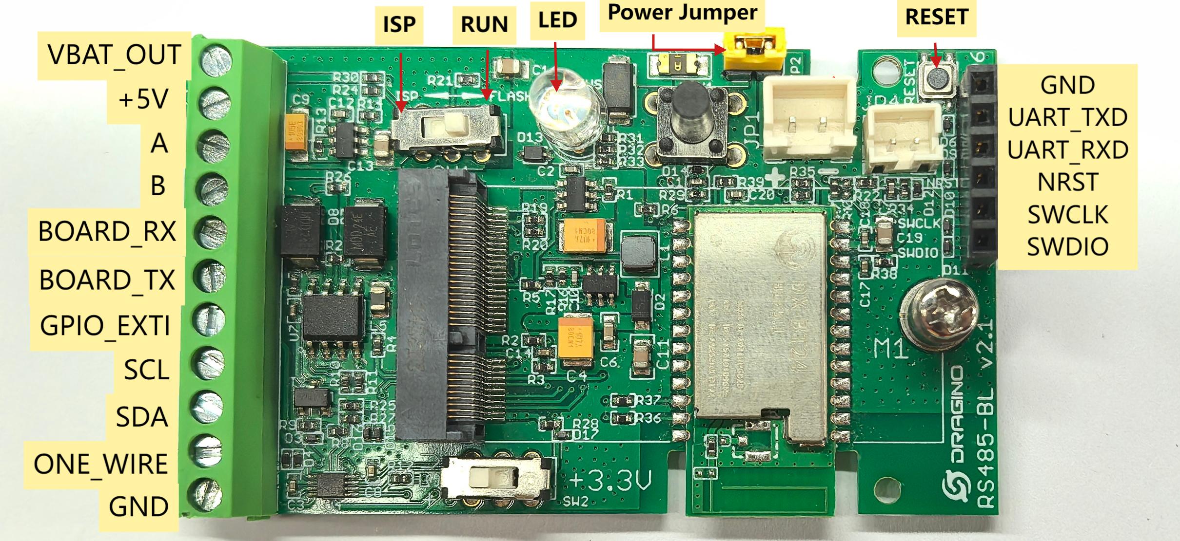
The following figures show the DDS75-MS board connections, ultrasonic probe, solar enclosure, mounting points, and cable outlets.
Board pin definitions
Ultrasonic probe mechanical reference
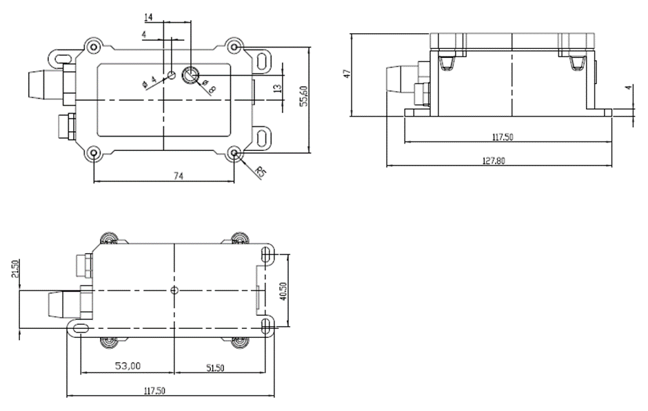
Ultrasonic probe dimensions
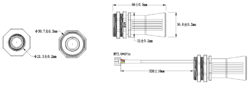
Solar enclosure dimensions and mounting reference
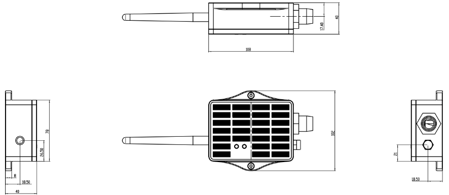
Install the enclosure above ground with cable outlets facing downward. Select cable glands suitable for the connected cables, seal unused openings, and provide a drip loop so water does not run along a cable toward the enclosure.
1.9 Distance Measurement and Operating Modes
1.9.1 Distance Measurement
The sensor returns one processed distance in millimetres. The firmware accepts values from 280 mm through 7500 mm. A response with no bytes is classified as No sensor. A response with data that fails frame, protocol, CRC, or range validation is classified as Invalid.
The measured object should be positioned within the sensor beam and provide a suitable reflective surface. Installation angle, object shape, surface condition, and obstructions can affect the result.
1.9.2 Normal Mode
Normal mode performs one sensor acquisition during each full Mesh wake. The result is published with its measurement status. The packet remains available when the result is No sensor or Invalid so the receiver can distinguish a missing or unusable measurement from a valid distance.
1.9.3 Delta Mode
Delta mode uses a baseline and auxiliary sensor samples:
- The first valid monitoring sample establishes the baseline.
- Later valid samples are compared with the active baseline.
- An event starts only when the absolute difference is greater than the configured threshold.
- No sensor and Invalid samples do not change the baseline.
- After a trigger, the node captures the configured number of burst samples.
The event retains the baseline and triggering distance and is published before a normal periodic reading. A pending event remains active until the packet is accepted by the local Mesh send queue.
1.10 Installation
- Select a measurement position with a clear path between the ultrasonic sensor and the target object.
- Keep the sensor aligned with the monitored surface and avoid nearby objects that can reflect or obstruct the ultrasonic beam.
- Confirm the sensor supply, RS485 wiring, address, and
9600 8N1communication settings before connecting the sensor. - Install the enclosure above ground with cable outlets facing downward.
- Protect the sensor cable from pulling, crushing, sharp bends, and standing water.
- Install the antenna vertically and place the solar panel where it receives stable, unobstructed sunlight.
- Complete the product-specific verification in Section 2.2 before relying on the measurement for the application.
2. Mesh Operation
2.1 How It Works
The node can communicate directly with a Mesh gateway or relay its data through other awake Mesh Nodes.
During a normal full wake, DDS75-MS powers the ultrasonic sensor, waits for warm-up, reads one Modbus distance value, validates the response, and publishes a type 0x07 Business Data packet. In Delta mode, auxiliary sensor-only wakes monitor the distance between full wakes. A triggered burst produces a type 0x08 event packet and takes priority over the normal periodic result.
The Mesh gateway receives:
- Measurement status and distance in Normal mode.
- Baseline, triggering distance, and burst samples in Delta mode.
- Battery information, device status, and the common Mesh Business Data header.
2.2 Product-Specific Verification
Complete the general enrollment and first-report procedure in the Mesh Quick Start before final installation. Use the checks below to validate the sensor path and the selected operating mode.
| Stage | Verify | Expected result |
|---|---|---|
| Sensor interface | Power, RS485 A/B wiring, address 0x01, and 9600 8N1 communication | The sensor responds without a wiring or protocol error |
| Normal measurement | A full wake with the target object in the measurement range | A valid distance is reported, or the packet clearly reports No sensor or Invalid |
| Target alignment | Sensor angle, beam clearance, target surface, and installation distance | The reading is stable and corresponds to the physical distance to the target |
| Delta mode | Baseline, threshold, sample interval, and burst count | A change greater than the threshold creates one delta event with the configured number of samples |
| Delta event | A burst containing valid, No sensor, or Invalid samples | Each sample keeps its own status, and unavailable samples do not corrupt valid distance values |
| Final installation | A new report after mounting the enclosure, sensor, antenna, and solar panel | The measurement remains plausible and the installation is mechanically secure |
2.3 Mesh Payload
DDS75-MS sends its Business Data on Mesh application port 290.
The common Sensors envelope is documented in 2.4 Mesh Business Data. This section defines the DDS75-MS-specific data after the common envelope. Multi-byte values are little-endian.
Normal DATA Structure
Normal mode uses data_type = 0x07. The complete packet is 20 bytes.
| Payload offset | Size | Field | Interpretation |
|---|---|---|---|
| 17 | 1 | reading_status | 1 = Valid; 2 = No sensor; 3 = Invalid |
| 18–19 | 2 | distance_mm | uint16 LE distance in millimetres when status is Valid; 0xffff otherwise |
For a Valid result, the distance is within 280 to 7500 mm. No sensor means that no response bytes were received. Invalid means that bytes were received but frame, protocol, CRC, or range validation failed.
Delta DATA Structure
Delta mode uses data_type = 0x08. The complete packet length is 22 + 3 × N bytes, where N is the configured sample count from 5 to 20. The resulting packet length is 37 to 82 bytes.
| Payload offset | Size | Field | Interpretation |
|---|---|---|---|
| 17–18 | 2 | baseline_mm | uint16 LE active baseline before the trigger |
| 19–20 | 2 | trigger_distance_mm | uint16 LE distance that triggered the event |
| 21 | 1 | sample_count | Number of burst samples, 5 to 20 |
22 + 3 × i | 1 | sample_i_status | 1 = Valid; 2 = No sensor; 3 = Invalid |
23 + 3 × i | 2 | sample_i_distance_mm | uint16 LE distance when status is Valid; 0xffff for No sensor or Invalid |
The receiver must use sample_count to validate the packet length. A delta event can contain individual No sensor or Invalid samples; these statuses are part of the event record.
3. Configure DDS75-MS
3.1 Configuration Method
Common Mesh configuration and enrollment are managed through the Mesh gateway. Use the Mesh Quick Start for the current enrollment and network workflow.
The DDS75-MS product configuration is available through the Mesh gateway or a supported configuration tool such as MeshDebug or FirmwareUpdateUtility. Product configuration uses Mesh port 295.
The configuration is stored persistently. A valid configuration is applied without reboot when the product lifecycle is idle. The node returns BUSY while an acquisition, auxiliary sample, or pending delta event is active.
3.2 Region and Radio Parameters
Each unit ships with a fixed Region and LoRa parameters set during manufacturing. The Mesh gateway and node must use the same Region.
3.3 Scheduled and Manual Reporting
After enrollment, the node follows the wake-up and reporting schedule provided by the Mesh gateway.
To request an immediate update:
- Wake the node if it is sleeping.
- While it is active, hold the button and release it within 1 to 3 seconds.
- Allow the sensor warm-up and acquisition cycle to complete.
- Confirm that the distance status, distance value when valid, and update time appear on the Mesh gateway.
In Delta mode, the auxiliary sample interval is independent of the ordinary Mesh reporting interval. Manual sleep is deferred while a delta event is pending.
3.4 DDS75-MS Configuration Parameters
| Parameter | Default | Valid values | Description |
|---|---|---|---|
work_mode | Normal | Normal or Delta | Selects periodic-only measurement or delta monitoring |
sample_interval_sec | 60 s | 1 to 3600 s | Interval between Delta mode monitor samples |
delta_threshold_cm | 30 cm | 1 to 750 cm | Trigger threshold; the event starts only when the change is greater than this value |
delta_sample_count | 10 | 5 to 20 | Number of samples captured in a delta event burst |
Applying a committed configuration resets the acquisition state, baseline, pending delta event, and schedules the behavior for the selected mode.
4. Battery & Power Consumption
Battery performance depends on the Mesh reporting interval, delta sample interval, number of delta events, Mesh coverage, relay conditions, sunlight, solar-panel orientation, ambient temperature, and battery condition.
Delta mode can use more energy than Normal mode because it performs additional sensor-only samples and can create extra event transmissions. A shorter sample interval, lower threshold, or larger number of delta events increases energy use.
DDS75-MS uses a solar panel and a 3000 mAh rechargeable lithium battery.
Battery Info & Power Consumption Analyze.
5. Firmware Update
Use only APP firmware built for DDS75-MS and the device's shipping Region.
For firmware preparation and upload, see 2. How to upload the firmware.
The firmware target is dragino-stm32-node-DDS75-MS.
6. FAQ
6.1 Why does DDS75-MS report No sensor?
No sensor means that the firmware received no response bytes from the RS485 sensor. Check the sensor power, RS485 A/B wiring, cable, sensor address, and interface enable signals.
6.2 Why is a distance reported as Invalid?
Invalid means that bytes were received but the response failed frame, protocol, CRC, or range validation. Confirm the sensor communication settings and keep the target within the valid 280 to 7500 mm range.
6.3 Why does Delta mode not trigger at the exact threshold?
The firmware uses a strict comparison. A delta event starts only when the absolute distance change is greater than the configured threshold. Equality does not trigger an event.
6.4 Why is the delta event not sent immediately?
After a trigger, the node captures the configured burst before publishing the event. The event remains pending until the packet is accepted by the local Mesh send queue, and it has priority over a normal periodic reading.
6.5 What happens when a delta sample is unavailable?
No sensor and Invalid samples are included with their status and a distance value of 0xffff. They do not change the active baseline during monitoring.
6.6 How should DDS75-MS be maintained?
- Keep the solar panel clean and unobstructed.
- Inspect the antenna, enclosure, cable glands, RS485 cable, and drip loop.
- Keep the ultrasonic face clean and clear of material that could obstruct the measurement beam.
- Check the sensor alignment and target position after mechanical work or relocation.
- Trigger a report after maintenance and confirm the distance status and value.
For enrollment, Region, gateway connectivity, general power, or firmware-update questions, see the general Mesh FAQ.
7. Order Info
Ordering details and Region-specific part numbers for DDS75-MS will be added when the product options are finalized.
8. Packing Info
Package contents, dimensions, and weights for DDS75-MS will be added in a future documentation update.
9. Support
Dragino support is available Monday to Friday from 09:00 to 18:00 GMT+8. When requesting assistance, provide the product model, firmware identification, Region, work mode, distance conditions, sensor wiring, and the steps required to reproduce the problem.
Contact: Support@dragino.cc