MA01-LN Mesh to LoRaWAN Adapter
MA01-LN User Manual
1. Introduction
1.1 What is MA01-LN Mesh to LoRaWAN Adapter
MA01-LN Mesh to LoRaWAN Adapter is a Long Range LoRaWAN device and local Mesh gateway. It is designed for outdoor and industrial use, and is suitable for long term powered installations with a built-in 3000mAh rechargeable Li-ion battery as power backup.
MA01-LN receives sensor data from local Mesh Nodes and forwards the data to TTN or other LoRaWAN network servers. This helps users deploy LoRa and IoT applications with flexible local Mesh coverage and standard LoRaWAN cloud connection.
MA01-LN wireless part is based on SX1262. It allows the user to send data and reach long ranges at low data-rates. It provides long range spread spectrum communication and high interference immunity, and targets professional wireless sensor network applications such as irrigation systems, smart metering, smart cities, industrial monitoring and so on.
MA01-LN has a powerful 48MHz ARM microcontroller with 256KB flash and 64KB RAM. It supports Mesh node table management, multi-node batch uplink and online / offline cache.
MA01-LN has a built-in BLE module. User can configure MA01-LN remotely via Mobile Phone. It also support OTA upgrade via private LoRa protocol for easy maintaining.
1.2 Features
- LoRaWAN v1.0.3 Class C
- Support configuration by Bluetooth v5.1 and LoRaWAN remote configuration
- Support LoRaWAN frequency bands:
CN470/EU433/KR920/US915/EU868/AS923/AU915/IN865 - Built-in Dual LoRa modules.
- Support Dragino Mesh Network
- Support Mesh frequency bands:
CN/EU/RU/BR/IN/US/JP/TH/SG/PH - Support multi-gateway cooperation
- Powered by 12v DC
- Built-in 3000mAh rechargeable Li-ion battery
1.3 Specification
Common DC Characteristics:
- Supply Voltage: 12v DC power
- Operating Temperature: -40 ~ 85°C
Data cache:
- 100 RAM-first pending records for sensor data uplink buffer.
- 16KB Flash spare cache (224 -- 500 records) for sensor data uplink records.
Node table:
- Supports up to 100 Mesh Nodes Entry. Each entry includes
NodeID,DevEUI,AppKey, andstatus flagsin Flash and last seen in RAM.
LoRa Spec:
- 2 x LoRa Modules
- Frequency Range, Band 1 (HF): 862 ~ 1020 MHz.
- Max +22 dBm constant RF output.
- RX sensitivity: down to -139 dBm.
- Excellent blocking immunity.
Battery:
- 3000mAh rechargeable Li-ion battery.
1.4 BLE Configuration Interface
MA01-LN has a built-in BLE module. It is always powered and available for local configuration by Mobile BLE APP. User can connect to MA01-LN by phone, scan the QR code on the Mesh Node package, and read the node DevEUI and AppKey for managing it.
The APP will save the Mesh Network ID generated by the first connected MA01-LN. When connecting to other MA01-LN gateways, user can configure the same Mesh Network ID to make the gateways work in the same private Mesh network.
1.5 Button & LEDs
| Button Action | Function | Behavior |
|---|---|---|
 1-3s 1-3s | Status indication | When LoRaWAN has joined, the green LED turns on while the button is held. Else, the blue LED turns on while the button is held. |
| >3s | Enter OTA mode | The green LED blinks quickly about 5 times, the device resets and enters Dragino OTA bootloader. After the waiting window ends, the application starts again and joins the LoRaWAN network. |
 x5 x5 | Reset device | After 5 short presses within 5 seconds, the red LED turns on for about 3 seconds, then the device performs a software reset. |
LED Status:
| LED | Status | Description |
|---|---|---|
| Green LED | LoRaWAN joined | After the device successfully joins the LoRaWAN network, the green LED turns on for about 5 seconds. |
| Green LED | LoRaWAN downlink | After receiving LoRaWAN downlink data or configuration command, the green LED turns on for about 500 ms. |
| Blue LED | LoRaWAN uplink | After the uplink request is accepted by LoRaWAN MAC, the blue LED turns on for about 500 ms. |
Note: :
Five-click reset and long press do not clear LoRaWAN or Mesh configuration. To restore configuration, use the AT+FDR command or the upgrade tool.
1.6 Download Resources
| Resource | Download Link |
|---|---|
| Firmware | https://www.dropbox.com/scl/fo/3ulvvv8wybfp3q7nhfher/AM0Z2l3PXQqDmutQjS5bM18?rlkey=c7hmcpcbj1j5si0namgwjp4d1&st=segpui8q&dl=0 |
| Burning Tool | https://www.dropbox.com/sh/j0qyc7a9ejit7jk/AACtx2tK4gEv6YFXMIVUM4dLa?dl=0 |
| Mobile BLE APP | Download "Devices.tool" from Google Play Store / App Store |
| Decoder | https://github.com/dragino/dragino-end-node-decoder/tree/main/ |
2. Configure MA01-LN to Connect to LoRaWAN Network
2.1 How it works
MA01-LN is configured as LoRaWAN OTAA Class C mode by default. It has OTAA keys to join a LoRaWAN network. To connect MA01-LN to a local LoRaWAN network, input the OTAA keys in the LoRaWAN IoT server, ensure normal power supply to the device, and then press the button to activate the device. MA01-LN will automatically join the LoRaWAN network via OTAA.
After joining the LoRaWAN network, MA01-LN will forward Mesh Node sensor data to the LoRaWAN server and upload MA01-LN device status.
2.2 Quick guide to connect to LoRaWAN server (OTAA)
Following is an example for how to join the TTN v3 LoRaWAN Network. Below is the network structure; we use the LPS8v2 as a LoRaWAN gateway in this example.
The LPS8v2 is already set to connected to TTN network, so what we need to now is configure the TTN server.
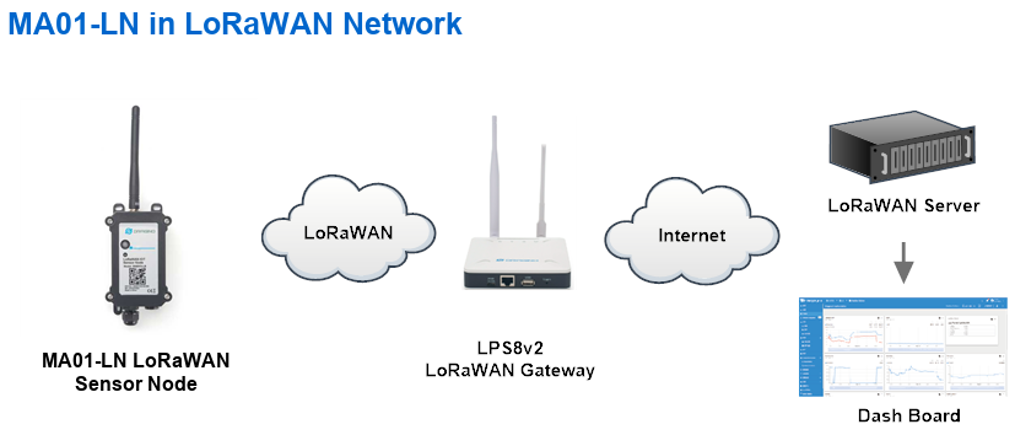
Step 1: Create a device in TTN with the OTAA keys from MA01-LN
Each MA01-LN is shipped with a sticker with the default device EUI as below:
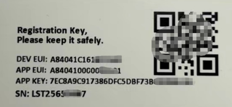
You can enter this key in the LoRaWAN Server portal. Below is TTN screen shot:
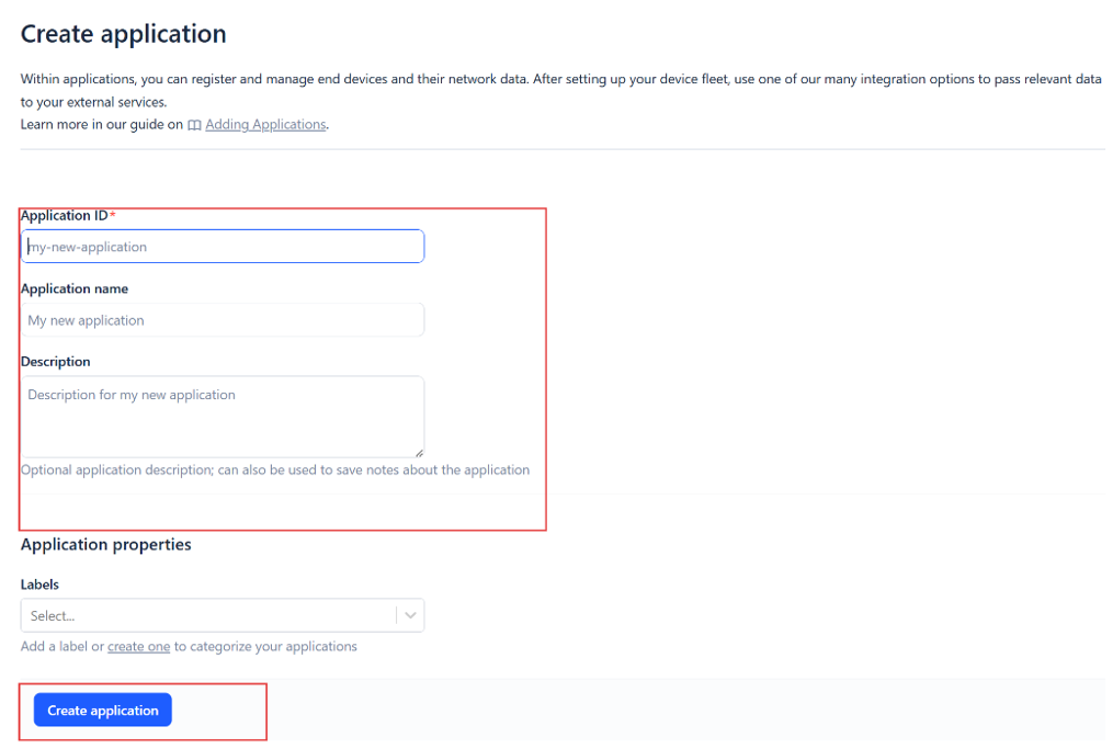
1. Create the application.

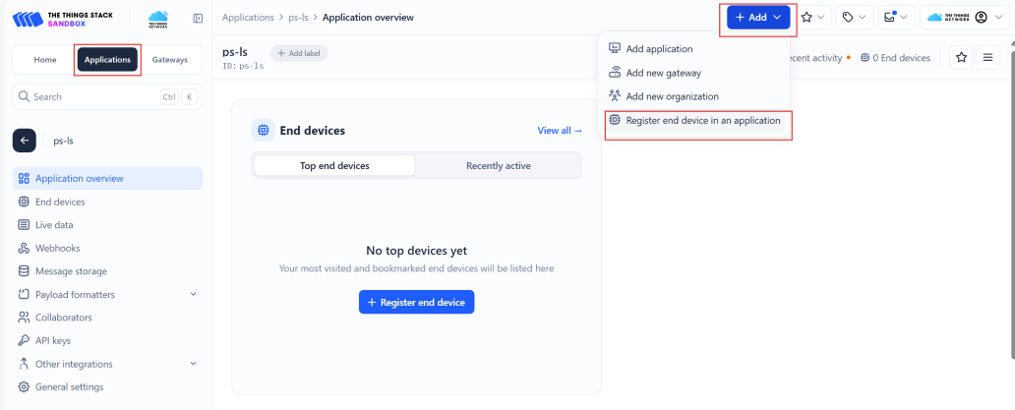
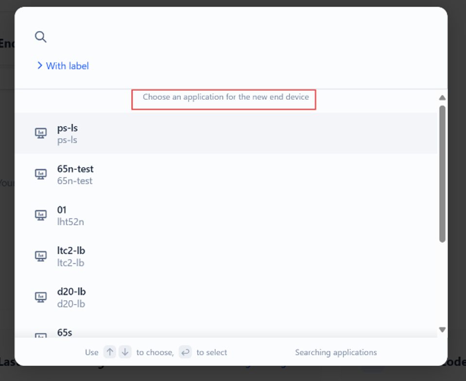
2. Add devices to the created Application.
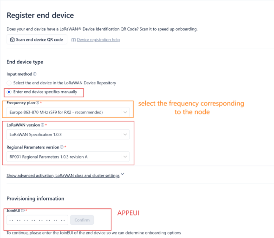
3. Enter end device specifics manually.
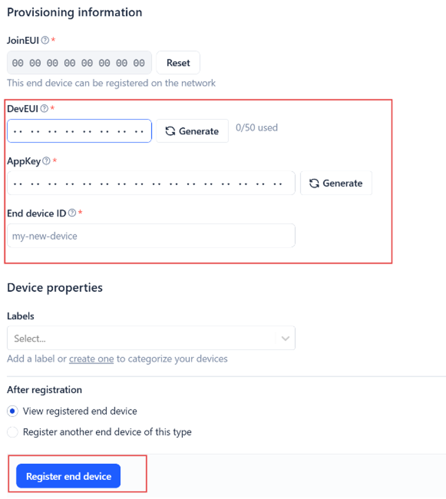
4. Add DevEUI and AppKey.
5. Customize a platform ID for the device.
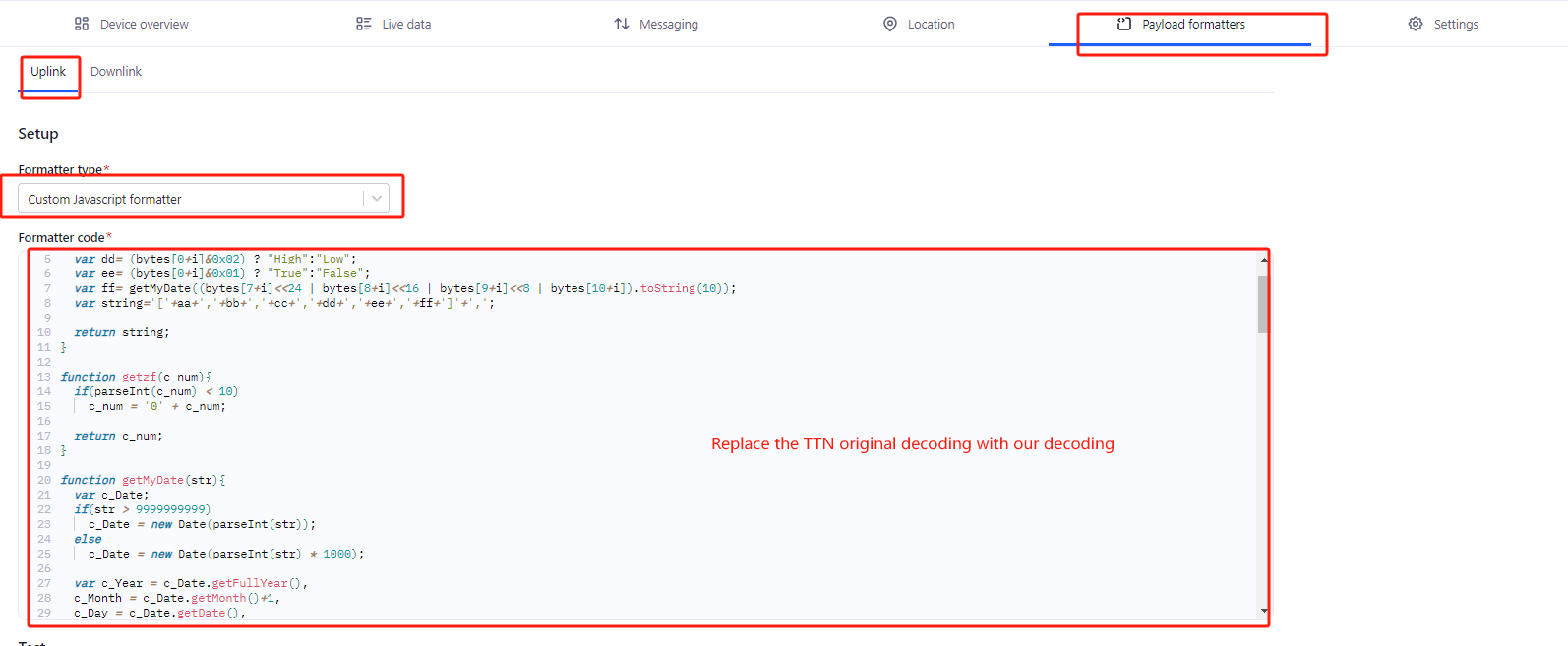
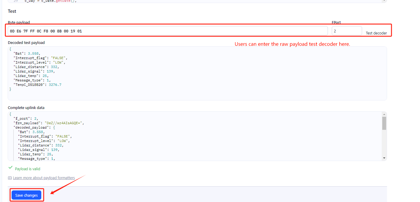
Step 2: Add decoder
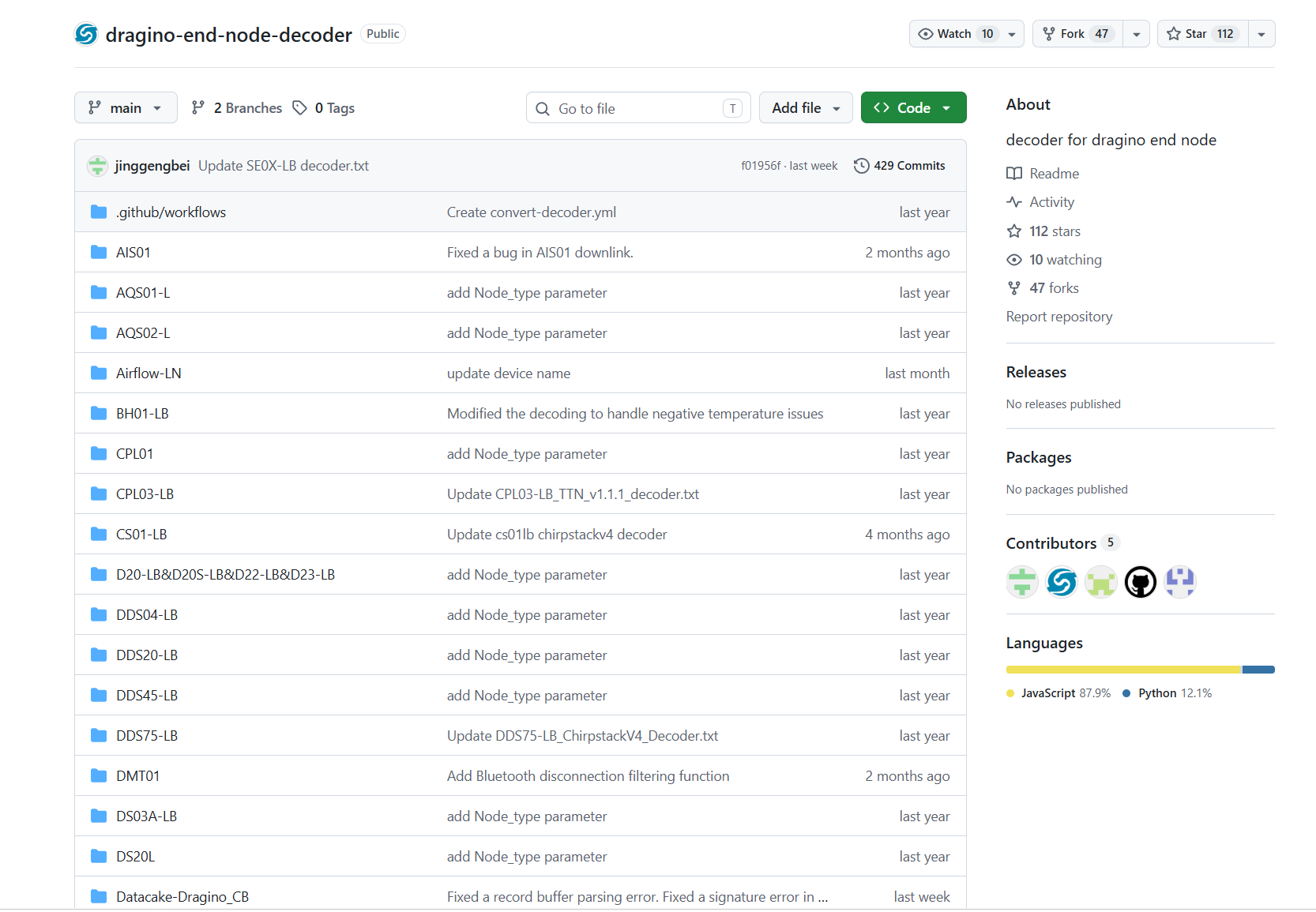
In TTN, user can add a custom payload so it shows friendly reading.
Click this link to get the decoder: https://github.com/dragino/dragino-end-node-decoder/tree/main/
Below is TTN screen shot:
Step 3: Activate MA01-LNs
Press the button for 3 seconds, green led will fast blink 5 times, device will enter OTA mode for 3 seconds. And then start to JOIN LoRaWAN network. Green led will solidly turn on for 5 seconds after joined in network.
After join success, it will start to upload messages to TTN and you can see the messages in the panel.
2.3 Frequency Plans
In LoRaWAN and Mesh network, MA01-LN uses different frequency band by different firmware. Please choose the current firmware version according to the country to deploy the product.
LoRaWAN: End Device Frequency Band | Dragino Documentation Center
Mesh: Frequency Plan | Dragino Documentation Center
3. Configuration for Mesh Network
3.1 Check Mesh Network
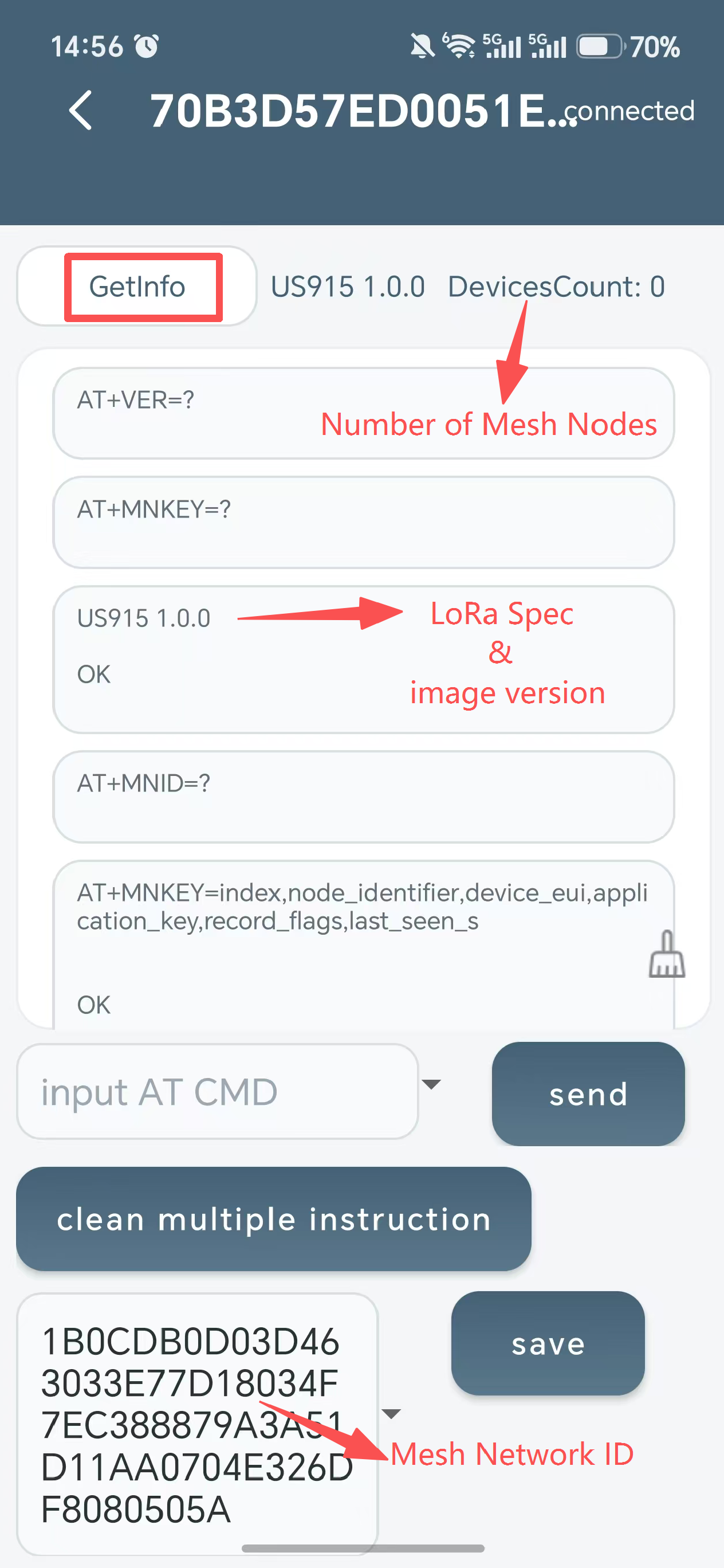
MA01-LN by default generates its own mesh network. After user connect to the MA01-LN via BLE( for detailed BLE connection and configuration steps, see BLE Configure Instruction), they can check the Mesh Network Info, which shows:
- Mesh Network ID
- Network LoRa Spec.
- Number of Mesh Nodes
- Mesh network Spec
Note: :
User can change the Network ID so several Mesh Gateway set up a multiply gateway mesh network. More info, please check FAQ: Multiple gateway mesh network.
3.2 Configure Mesh Network Synchronized Wake-up
Synchronized Wake-up gives nodes the same predictable wake-up rhythm while MA01-LN remains powered and available as the gateway. After Mesh time is synchronized, nodes using the same plan wake in a common receive window, transmit sensor data or management packets.
User-configurable settings:
- interval_min: a positive whole number that defines how often the node wakes, in minutes. For example,
AT+MNWAKE=40means nodes will wake up at 00:00, 00:40, 01:20 and so on. Select the interval according to the required reporting latency and power budget.
Fixed system settings:
- Startup delay: 15 seconds. After a node wakes for its scheduled window, it waits for the system, sensors, and radio to become ready.
- Random delay: 0 to 15 seconds. After startup, the node adds a random wait before its first data or management transmission. This staggers transmissions from nodes that use the same schedule, reducing the chance of radio collisions. it does not move the next scheduled wake-up point.
- Gateway wait: 90 seconds. After reporting, the node remains available to receive a gateway command during this period.
How to configure:
- Before applying a common wake-up plan, make sure MA01-LN has joined LoRaWAN and all nodes keep awake.
- Choose a plan for your application. For example,
AT+MNWAKE=30configures the network for the common 30-minute xx:00 / xx:30 schedule. - Send the AT Command through BLE APP.
Note: :
A node will get the Synchronized Wake-up configuration of the network when it joins. So, it is not necessary to send AT+MNWAKE when you add a new node.
3.3 Add a Mesh Node
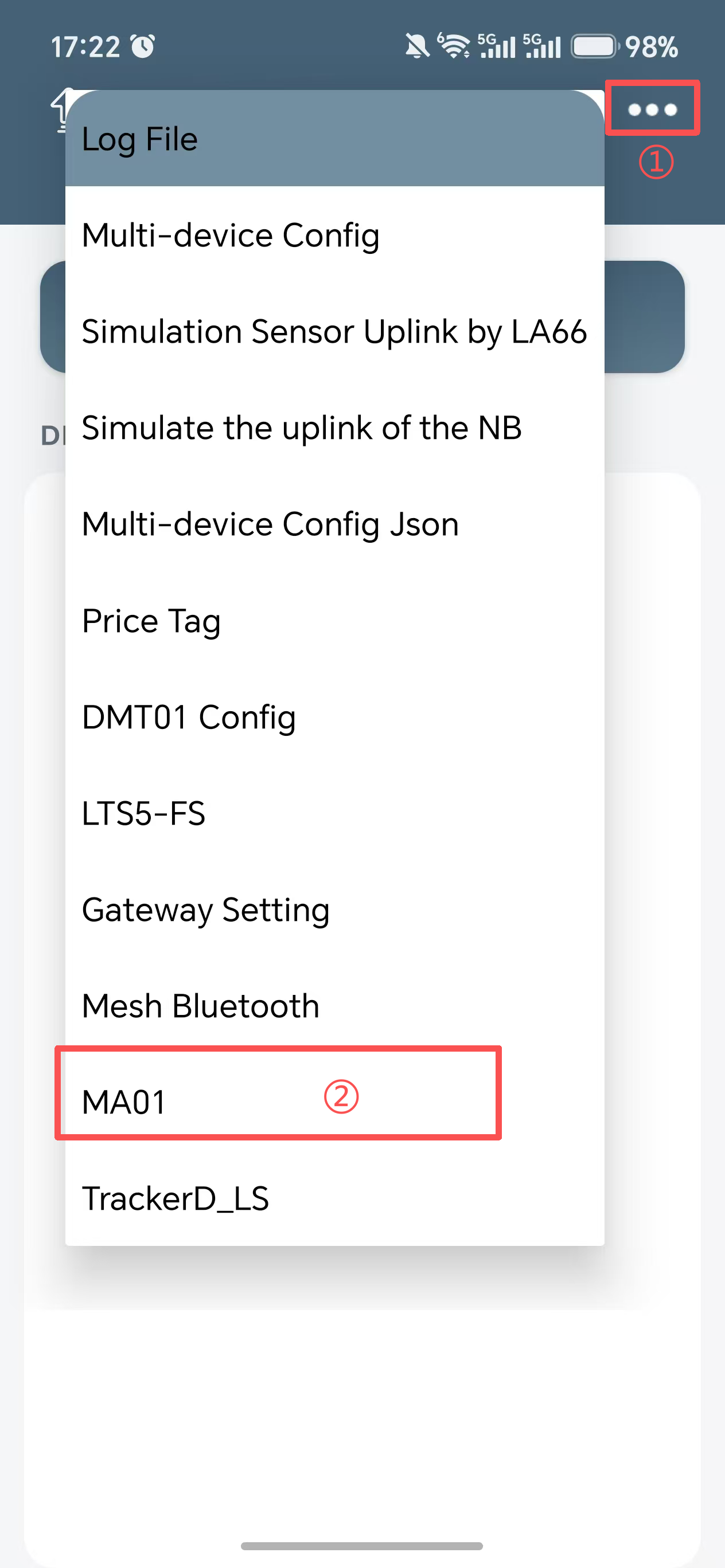
Step 1. Download the mobile BLE app Devices.tool. Open it, tap the three horizontal dots (•••) in the upper-right corner, and select MA01-LN.
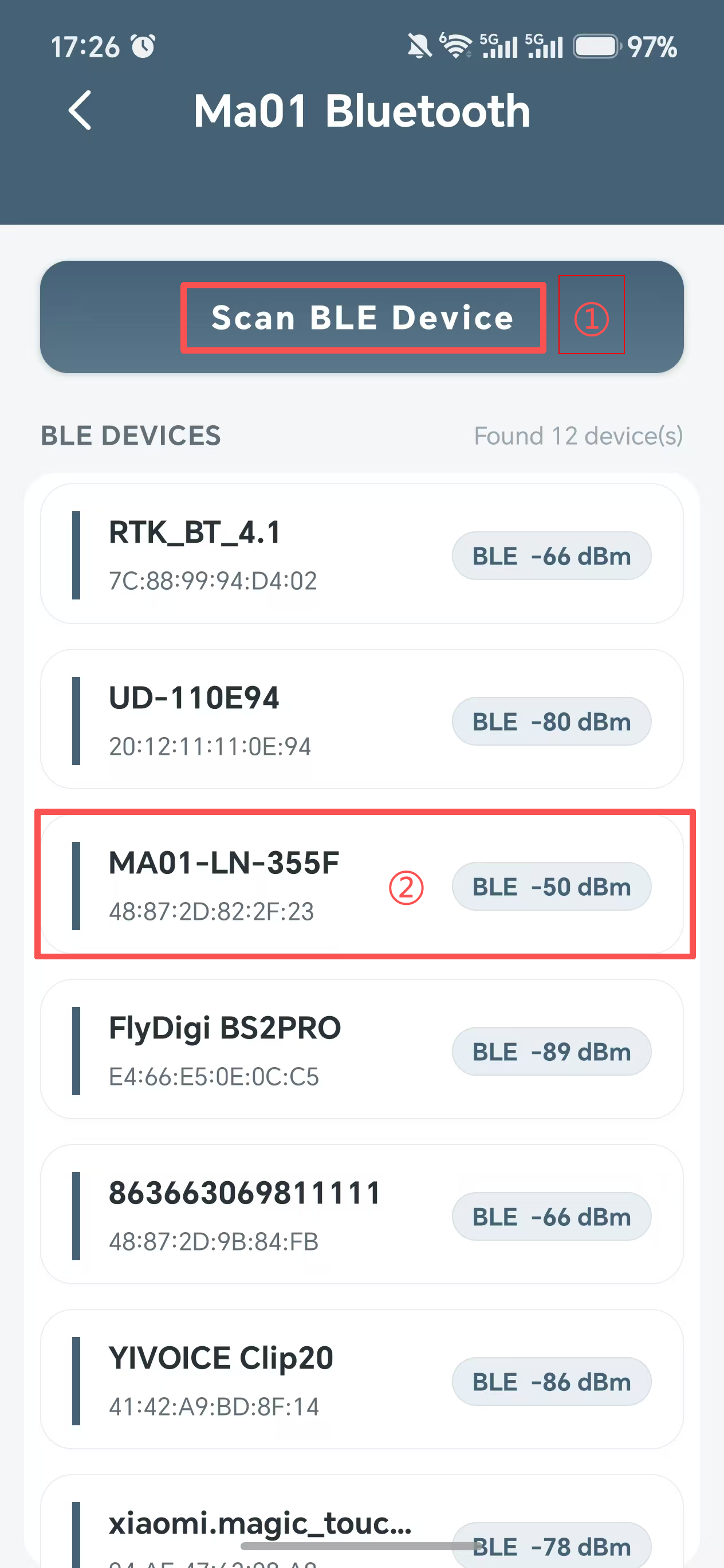
Step 2. Tap Scan BLE Device to search for the MA01-LN device. The device name is MA01-LN + the last 4 characters of the DevEUI (e.g., MA01-LN-358D). Locate the target device and tap to enter.
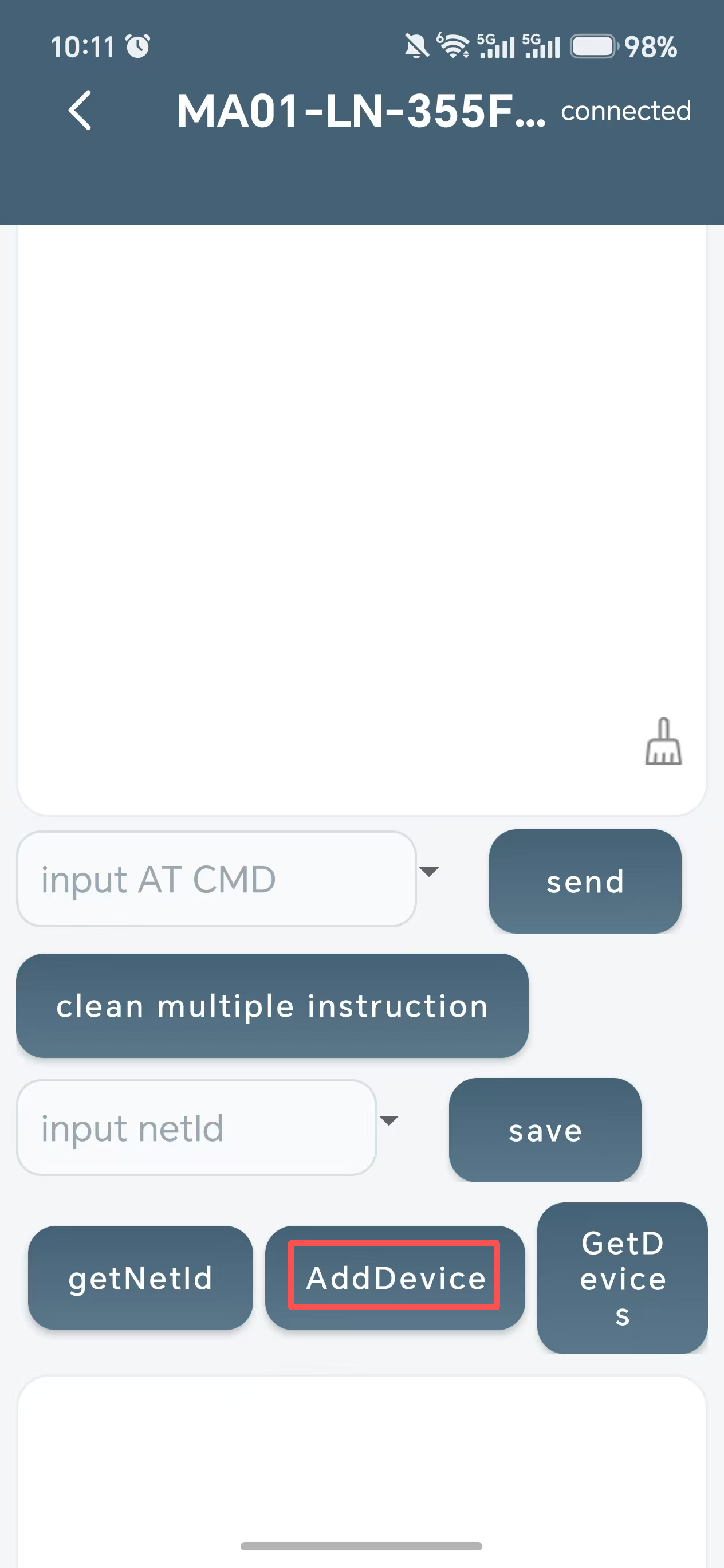
Step 3. On the device page, tap Add Device and scan the QR code on the Mesh node packaging box. MA01-LN will obtain the DevEUI and APPKEY of the Mesh node and add it to the MA01-LN network.
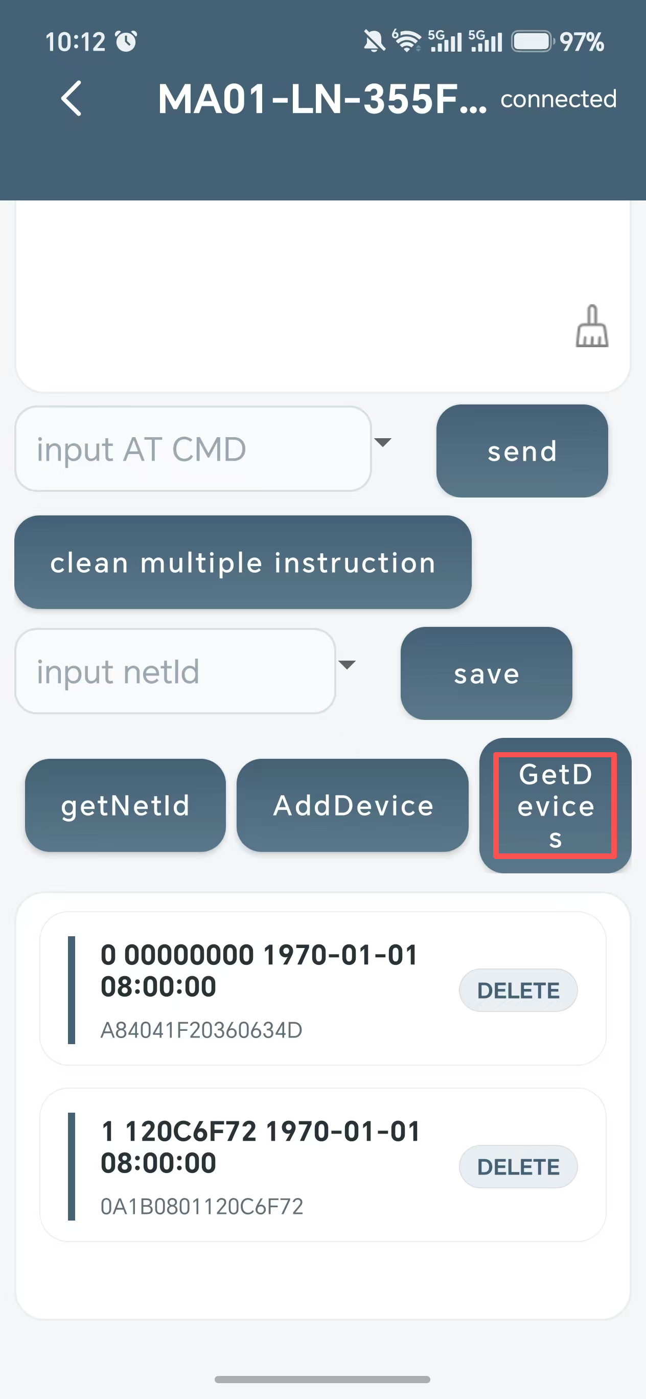
Step 4. If the page prompts you to enter the MA01-LN device password, tap the input field and enter the last 6 characters of the APPSKEY (the APPSKEY information is provided on the product packaging box). Then tap GetDevices to check whether the device has been added successfully.
Step 5. If you cannot scan the QR code, use an AT command to add the Mesh node manually:
AT command
AT+MNKEY=<DevEUI16>,<AppKey32>
Example
AT+MNKEY=1234567812345678,12345678123456781234567812345678
NOTE: :
The node cannot join the Mesh network while it is sleeping, so please wait for the next wakeup or keep the node awake.
4. Uplink Payload and Decoder
4.1 Decode payload
While using TTN V3 network, you can add the payload format to decode the payload. The payload decoder function for TTN V3 are here:MA01-LN TTN V3 Payload Decoder
4.2 FPort 5 device status payload
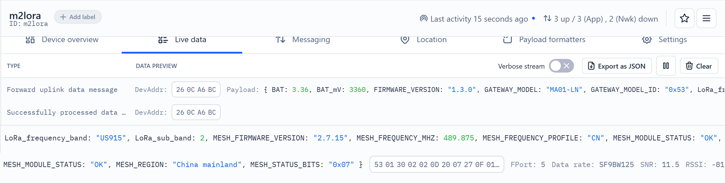
Users can use the downlink command (0x26 01) to ask MA01-LN to send device status details. MA01-LN will uplink a payload via FPort 5 to the server.
In addition, when link detection is triggered and no Mesh pending data is available, a confirmed FPort 5 device status is used as the heartbeat every 5 minutes.
The first 7 bytes keep the original Dragino device status format. Bytes 7 to 10 add Mesh module interaction status, Mesh firmware version and Mesh frequency profile.
The Payload format is as below.
Device Status (FPORT=5)
| Size (bytes) | 1 | 2 | 1 | 1 | 2 | 1 | 2 | 1 |
|---|---|---|---|---|---|---|---|---|
| Value | Gateway Model | Firmware Version | LoRa Frequency Band | LoRa Sub-band | BAT | Mesh Module Status | Mesh Firmware Version | Mesh Frequency Profile |
Example parse in TTNv3
Gateway Model: For MA01-LN, this value is 0x53.
MA01-LN Firmware Version: 0x0100 means firmware v1.0.0 version.
LoRa Frequency Band:
0x01: EU8680x02: US9150x03: IN8650x04: AU9150x05: KZ8650x06: RU8640x07: AS9230x08: AS923-10x09: AS923-20x0a: AS923-30x0b: CN4700x0c: EU4330x0d: KR9200x0e: MA869
LoRa Sub-band:
AU915 and US915: value 0x00 ~ 0x08
CN470: value 0x0B ~ 0x0C
Other bands: always 0x00
Battery Info:
Check the battery voltage. Ex1: 0x0B45 = 2885mV; Ex2: 0x0B49 = 2889mV.
Mesh Module Status:
MESH_MODULE_STATUS = OK: The Mesh module is normal.
MESH_MODULE_STATUS = CHECK: The query is incomplete.
Mesh Firmware Version:
Byte 8 stores major/minor: high 4 bits = major, low 4 bits = minor. Byte 9 stores patch.
0xFF: UNKNOWN.
Ex: byte8 = 0x25 and byte9 = 0x00 means v2.5.0.
Mesh Frequency Profile:
0x00: UNKNOWN0x01: CN / 489.875 MHz0x02: EU / 869.525 MHz0x03: RU / 868.825 MHz0x04: BR / 904.875 MHz0x05: IN / 866.375 MHz0x06: US / 921.375 MHz0x07: JP / 921.875 MHz0x08: TH / 922.375 MHz0x09: SG / 920.875 MHz0x0A: PH / 916.375 MHz
4.3 FPort 2 / FPort 3 Mesh sensor payload
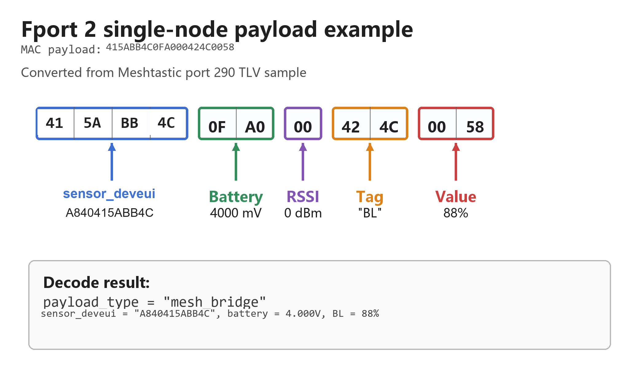
Single-node FPort 2 payload format:
| Size (bytes) | 4 | 2 | 1 | Repeated (2 + N) |
|---|---|---|---|---|
| Value | sensor_deveui | Battery (mV) | RSSI | Tag + Value |
Multi-node FPort 3 batch payload format:
| Size (bytes) | 1 | 1 | Repeated (1 + N) |
|---|---|---|---|
| Value | Version: 0x01 | Record Count | Record Len + Single Node Record |
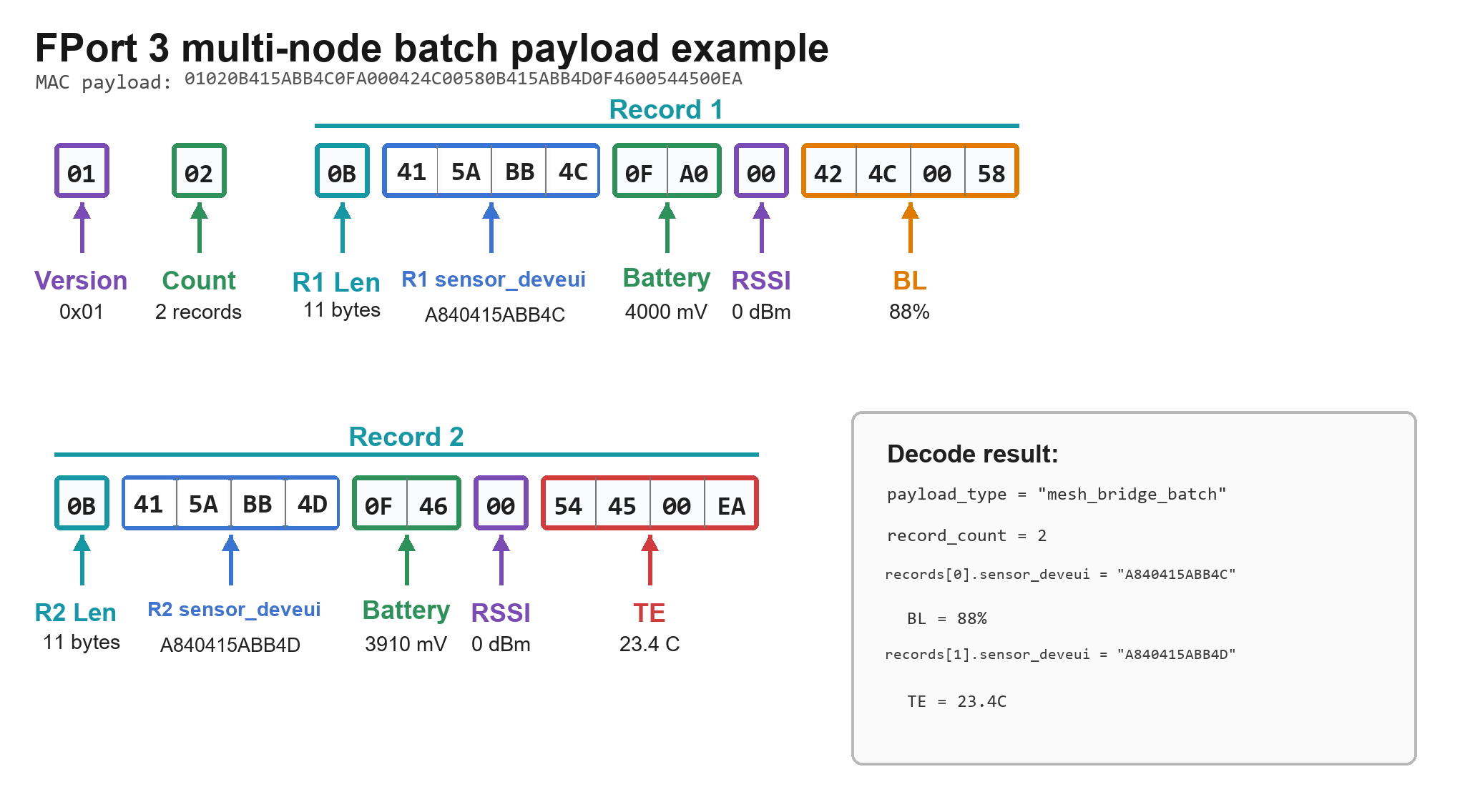
- MA01-LN sends one selected record on FPort 2 using the single-node format. When two or more records are packed together, it sends the batch on FPort 3.
- Record Count indicates how many records follow. Each record starts with a one-byte Record Len and then carries a complete Single Node Record.
- For both formats, the first 4 bytes of every single-node record are a fragment of the registered node DevEUI. For example,
A84041C9365ABB4Cis encoded and forwarded as415ABB4Cand decoded as sensor_deveuiA840415ABB4C.
4.4 FPort 2 tag table
| Tag | Name | Length | Unit / Encoding |
|---|---|---|---|
| BL | battery level | 2 | % |
| VO | voltage | 2 | mV |
| TE | temperature | 2 | int16, x10 |
| HU | humidity | 2 | uint16, x10 |
| BP | barometric pressure | 2 | uint16, x10 |
| LX | illuminance | 2 | uint16, x10 |
| CR | current | 2 | mA |
| A1/A2/A3 | ADC voltage | 2 | mV |
| C1/C2/C3 | channel current | 2 | mA |
| DB | noise | 2 | uint16, x10 dB |
| CO | CO2 | 2 | ppm |
| PM | PM2.5 | 2 | ug/m3 |
| P1 | PM10 | 2 | ug/m3 |
| DS | distance | 2 | uint16, x10 cm |
| WL | water level | 2 | uint16, x10 cm |
| PH | pH | 2 | uint16, x100 |
| EC | conductivity | 2 | uS/cm |
| DI/DO | digital input/output | 2 | raw |
| CT | count | 4 | raw |
| SM/ST | soil moisture / temperature | 2 | x10 |
| WS/WD/RN | wind / rain | 2 | x10 or degree |
4.5 Dynamic DR selection
MA01-LN selects the lowest legal DR that can contain the pending FPort 2 / FPort 3 payload. Different regions have different maximum uplink DR values.
4.6 TTN decoder examples
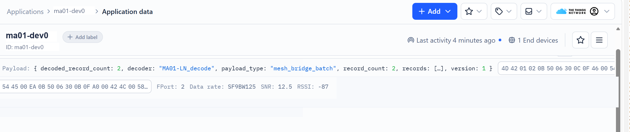
Single-node decoding result outputs payload_type="mesh_bridge". Batch decoding result outputs payload_type="mesh_bridge_batch", and lists the sensor_deveui and items of each Mesh Node in records[ ].
Decoder file: MA01-LN decoder
TTN FPort 2 single-node decode.

TTN FPort 3 batch decode.
Screenshot placeholder: TTN FPort 5 device status decode.
5. Configure MA01-LN
5.1 Configure Methods
MA01-LN supports below configure methods:
- AT Command via Bluetooth Connection (Recommended): BLE Configure Instruction.
- AT Command via UART Connection: See UART Connection.
- LoRaWAN Downlink. Instruction for different platforms: See IoT LoRaWAN Server section.
5.2 General Commands
MA01-LN keeps the common Dragino LoRaWAN AT command set for OTAA keys, frequency band, join status, Class C, ADR/DR and link detection parameters. These commands can be found on the wiki: End Device AT Commands and Downlink | Dragino Documentation Center
MA01-LN is a long-powered Mesh to LoRaWAN gateway. Mesh node data uplink is fixed to FPort 2 and FPort3, and MA01-LN device status uplink is fixed to FPort 5.
| Command Example | Function | Response |
|---|---|---|
AT+CFG | Print main system configuration. | System configuration list. |
ATZ | Software reset. | OK |
AT+FDR | Restore factory parameters according to firmware rules. | OK |
AT+VER=? | Query firmware version. | Firmware version string |
AT+JOIN | Trigger LoRaWAN OTAA join. | OK |
AT+NJS=? | Query LoRaWAN join status. | 0: not joined; 1: joined |
AT+CLASS=C | Set LoRaWAN Class C. | OK |
AT+ADR=1 | Enable LoRaWAN ADR. | OK |
AT+DR= <dr> | Set LoRaWAN data rate. | OK |
AT+DEBUG | Toggle detailed serial logs. The default log level enabled or default logs restored | Detailed logs enabled or default logs restored |
Parameter description:
| Parameter | Values and functions |
|---|---|
<dr> | LoRaWAN data rate index. Valid values depend on the firmware frequency band and regional parameters. |
AT+CLASS= | A/B/C. MA01-LN is intended for long-powered Class C operation. |
AT+ADR | 0: Disable ADR; 1: Enable ADR |
5.3 Commands special design for MA01-LN
The following commands are designed for Mesh Network ID, Mesh node table, node migration, offline cache and multi-gateway use.
5.3.1 Mesh Network and Node Table
AT+MNKEY: add or update one Mesh node by DevEUI and AppKey. After AppKey is configured, the node will join when it wakes up and broadcasts JoinLockAdvertise again.
AT+MNDEL: show a deletion confirmation prompt only. Use AT+MNDEL=<target>,1 to delete the local Flash node table record.
AT+MNID: set / change Mesh Network ID. Make sure all devices wake up before send the command.
| Command Example | Function | Response |
|---|---|---|
AT+MNINFO=? | Query MA01-LN Mesh gateway status. | Multi-line Mesh status |
AT+MNID=? | Query network private key ( Mesh Network ID ). | AT+MNID=network_private_key=<ID64> |
AT+MNID=<ID64> | Set the 32-byte network private key. | OK |
AT+MNKEY=<DevEUI16>,<AppKey32> | Add or update one Mesh Node AppKey by DevEUI. | OK |
AT+MNDEL=<index> or <DevEUI16> | Show the deletion confirmation prompt only; no local record is deleted. | Migration and deletion confirmation prompt |
AT+MNDEL=<index>,1 | Delete the local Flash node table record after confirmation. | OK; mesh node delete: idx=<n> node=0xXXXXXXXX deleted=1 |
Parameter description:
| Parameter | Values and functions |
|---|---|
<DevEUI16> | 8-byte device EUI in HEX format, 16 HEX characters. |
<AppKey32> | 16-byte application key in HEX format, 32 HEX characters. |
<ID64> | Full 32-byte network private key input. The value must be non-zero HEX. |
<index> | Decimal node table index shown by AT+MNKEY=?. |
5.3.2 Node Migration
Use AT+MNID=<ID64> to set a new Mesh Network ID, then all nodes will migrate to the new network.
To move single node to another Mesh network:
- Add the node DevEUI and AppKey to a gateway in the target Mesh network.
- Delete the node binding from every MA01-LN gateway in the original Mesh network with
AT+MNDEL=<target>,1. - Restart the node.
5.3.3 Multi-gateway Use
Multiple MA01-LN gateways can work in the same Mesh network when they use the same Mesh Network ID / network private key. Learn more on FAQ: Multiple gateway mesh network.
5.3.4 Data Cache
MA01-LN uses a two-level cache for Mesh sensor uplink data.
New Mesh sensor records are stored in the RAM pending queue first, which can hold up to 100 records. When the RAM queue is full, new records are stored in the 16 KB Flash cache.
When LoRaWAN is online but uplinks are temporarily accumulated, Flash uses a compact record format and can store about 204 additional records. In this condition, the total cache capacity is about 304 records.
When LoRaWAN is offline, after the RAM queue is full, Flash stores records by actual payload length. For maximum-length sensor records, Flash can store about 224 additional records. In this condition, the total cache capacity is about 324 maximum-length records. If the payload is shorter, the number of Flash records may be higher.
RAM and Flash records share one sequence number. After LoRaWAN uplink resumes, MA01-LN sends cached records in FIFO order according to the sequence number.
Use AT+MNCACHE=? to check the current RAM pending count, Flash pending count, Flash used bytes, dropped Flash records, and the oldest/newest sequence numbers.
| Command Example | Function | Response |
|---|---|---|
AT+MNCACHE=? | Query Mesh FPort 2/FPort 3 RAM pending queue and Flash cache status. | AT+MNCACHE: ram_pending_records=<n> ram_capacity_records=<n> flash_used_bytes=<n> flash_capacity_bytes=16384 flash_pending_records=<n> flash_dropped_records=<n> oldest_sequence=<n> newest_sequence=<n> |
AT+MNCACHE=CLR | Clear Mesh FPort 2/FPort 3 data cache. | mesh offline cache cleared OK |
5.3.5 Downlink and Device Status
MA01-LN only keeps LoRaWAN downlink commands related to gateway operation: 0x04, 0x20, 0x21, 0x22, 0x24, 0x26, 0x32 and 0x33.
Downlink 0x01, 0x05, 0x23 and 0x25 are not applicable to MA01-LN.
| Command Example | Function | Response |
|---|---|---|
Downlink: 0x26 01 | Request one FPort 5 device status uplink. | FPort 5 device status payload |
Downlink: 0x21 <level> | Set response_level for execution-result reply policy. | Execution result reply according to response_level |
Downlink: 0x21 00 <00\01> | Set DISMACANS / MAC command answer policy. | Execution result reply according to response_level |
Parameter description:
| Parameter | Values and functions |
|---|---|
<level> | Selects when MA01-LN reports command execution results. Valid values: 00 disables replies; 01 replies to unconfirmed downlinks with application data; 02 replies to confirmed downlinks with application data;03 replies to MAC commands;04 replies to MAC commands or confirmed downlinks with application data;05 replies to MAC commands or any downlink with application data. |
<00\01> | For DISMACANS style setting. 00 and 01 select whether MAC command answers are allowed according to Dragino LoRaWAN rules. |
Tip: :
For the complete parameter format of downlink commands, see:
https://wiki.dragino.com/docs/LoRaWAN-General-Configuration/at-commands-downlink/?_highlight=downlink
5.3.6 Link Detection and Rejoin
Unless a valid downlink is received, MA01-LN runs a confirmed probe every 5 minutes to insure the transmission of LoRaWan; failed ACK triggers immediate rejoin.
| Command Example | Function | Response |
|---|---|---|
AT+RJTDC=1 | Set rejoin retry interval to 1 minute. | OK |
AT+RJTDC=? | Query rejoin retry interval. | 1 |
5.3.7 Uplink Stability and Transmission Rate
When nodes report in batches, if the number of records received by the server is significantly less than the number actually reported, the packet loss rate can be considered high. Users can take the following measures in sequence to improve it.
Method 1: Adjust antenna orientation and reduce obstructions
Deploy the gateway antenna facing the direction where nodes are densely located, avoiding metal structures, wall obstructions, and strong electromagnetic interference sources to improve RF link quality. This method has no side effects and is recommended as the first choice.
Method 2: In regions without duty cycle restrictions, use AT+MUPMAX=1
This command switches the uplink single-packet capacity to the second-highest level. The single-packet capacity decreases, and the number of transmissions increases accordingly. Each record is sent in a shorter data frame, which can reduce the probability of single-frame collisions and thereby lower the packet loss rate. The cost is increased airtime occupancy and a lower overall transmission rate.
Method 3: In regions with duty cycle restrictions, use AT+MUPCFM=4 or AT+MUPCFM=3
This command shortens the confirmed report interval, improving transmission reliability and thereby reducing the packet loss rate. The cost is a slightly slower transmission rate.
Command Description
| Command | Description | Value Range | Default Value |
|---|---|---|---|
AT+MUPMAX=<0 or 1> | Uplink single-packet capacity level: 0 is the highest level, 1 is the second-highest level | 0 / 1 | 0 |
AT+MUPCFM=<1..255> | Include one confirmed report in every N uplink service packets | 1–255 | 5 |
The above commands support querying the current values in the forms AT+MUPMAX=? and AT+MUPCFM=?. The two commands are independent of each other; modifying one does not affect the other. The confirmed count only counts service packets successfully received at the MAC layer; failed submissions and retransmissions are not counted repeatedly. Parameter modifications are automatically saved and remain effective after restart.
Configuration example (US915 band):
AT+MUPMAX=1
AT+MUPCFM=10
After execution, the maximum records per single packet change from 4 records/226 bytes to 2 records/114 bytes, and the confirmed report frequency remains approximately once every 10 records.
Regions with Duty Cycle Transmission Restrictions
The following regions impose regulatory duty cycle restrictions on RF bands. After completing a transmission, the device must enter a mandatory waiting period, and the uplink transmission rate is constrained by this:
| Regional Scheme | Corresponding Region | Duty Cycle |
|---|---|---|
| EU868 | Europe 868 MHz | 0.1% / 1% / 10% (by sub-band) |
| EU433 | Europe 433 MHz | 1% |
| RU864 | Russia | 1% |
| CN779 | China 779 MHz scheme | 1% |
| KZ865 | Kazakhstan | 1% |
| MA869 | Morocco | 0.1% / 1% / 10% (by sub-band) |
The remaining regions are described as follows:
- US915, AU915, CN470, KR920: The current firmware does not enable duty cycle transmission restrictions;
- IN865: The duty cycle function flag is enabled, but the parameter is 100%, so no transmission waiting is generated;
- AS923: The current gateway disables duty cycle control; actual deployment countries may have different requirements. AS923 and AU915 are also subject to Dwell Time restrictions (single-packet dwell time). This restriction and duty cycle are two different constraints and cannot be calculated together.
Example: In a region with a 1% duty cycle, if a single packet occupies the air interface for 1 second, it is usually necessary to wait about 99 seconds before continuing transmission. Taking a 226-byte data packet (US915 DR3, airtime about 374 ms) as an example, in a restricted band, after each packet transmission, it is necessary to wait about 37 seconds. On average, about 48 packets can be sent within half an hour; switching channels within the same restricted band usually cannot bypass this restriction.
5.4 Commands Not Applicable to MA01-LN
Not recommended or not applicable AT commands: AT+TDC, AT+PORT, AT+MOD, AT+SLEEP, AT+GETSENSORVALUE.
Not applicable LoRaWAN downlink commands: 0x01, 0x05, 0x23 and 0x25.
6. MA01-LN Firmware Upgrade
6.1 For LoRaWAN module
User can change firmware to:
-
Change Frequency band/ region.
-
Update with new features.
-
Fix bugs.
Firmware and changelog can be downloaded from: https://www.dropbox.com/scl/fo/3ulvvv8wybfp3q7nhfher/AM0Z2l3PXQqDmutQjS5bM18?rlkey=c7hmcpcbj1j5si0namgwjp4d1&st=segpui8q&dl=0
Methods to Update Firmware:
-
(Recommended way) OTA firmware update via wireless: LoRaWAN OTA Firmware Update
-
Update through UART TTL interface: Instruction.
6.2 For Mesh Module
Firmware Update Software:
Step 1. Download the Firmware Update Software for your operating system from: https://github.com/dragino/MeshNode/releases#release-v1.1.0
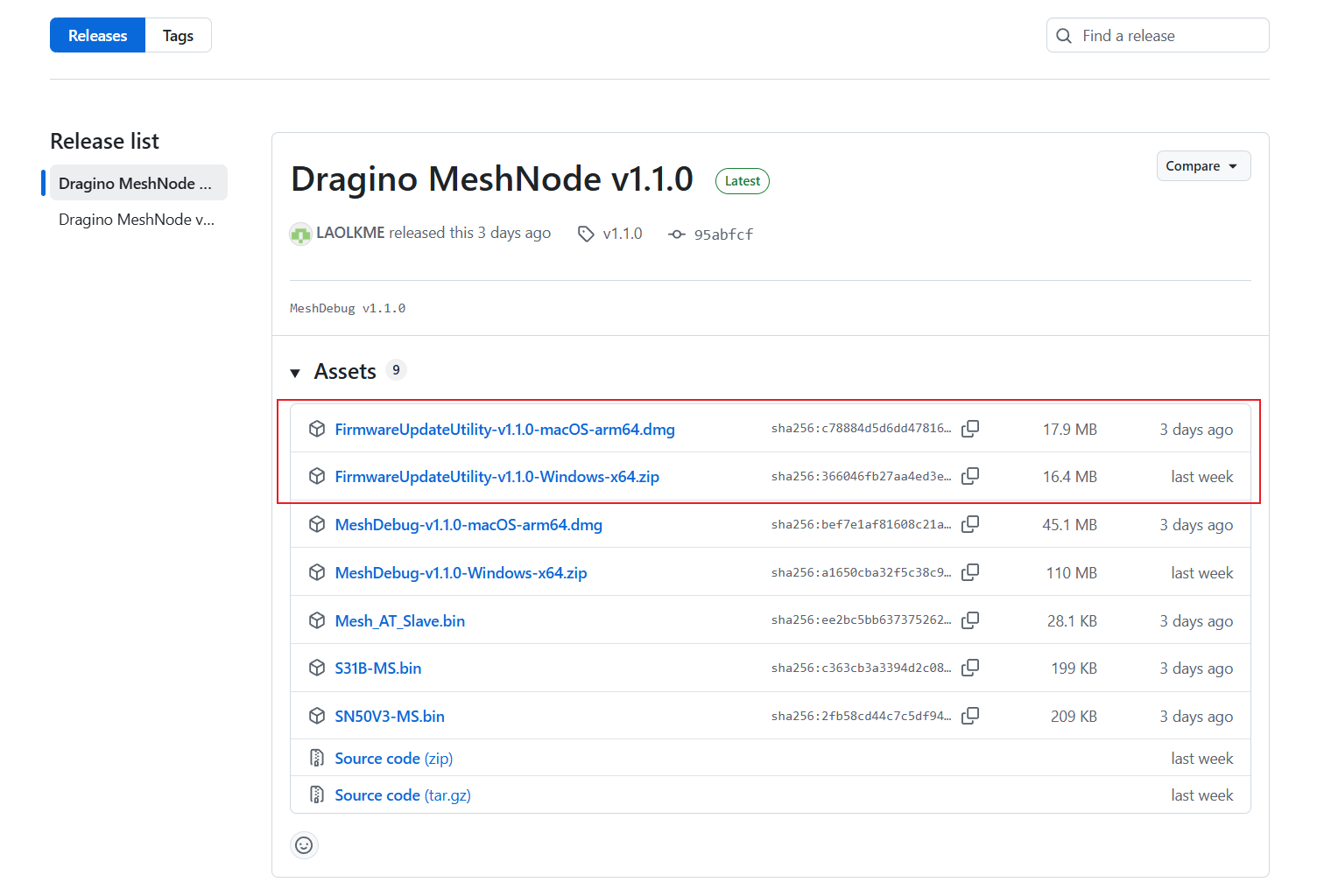
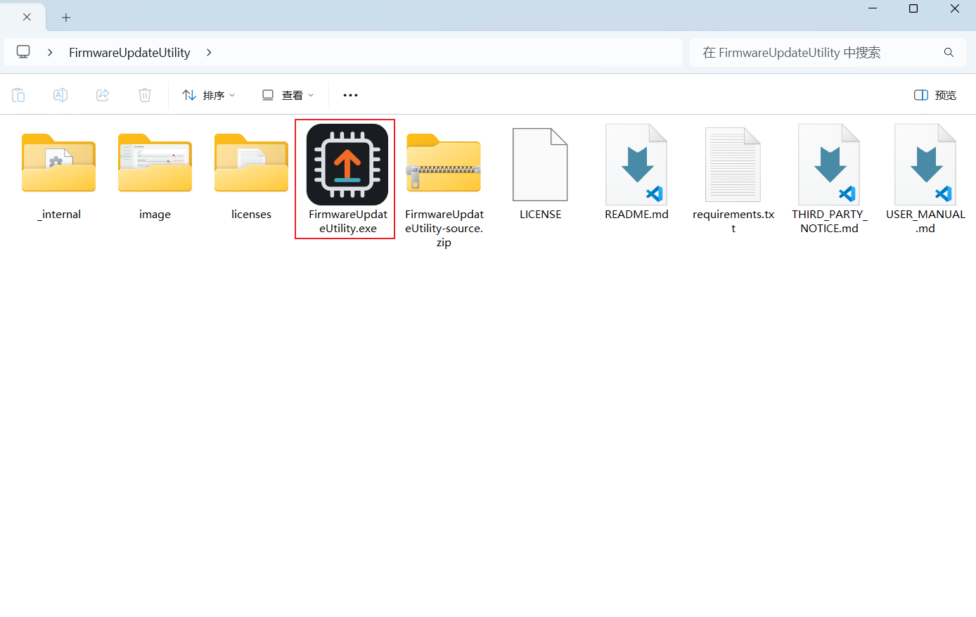
Step 2. Launch the FirmwareUpdateUtility program.
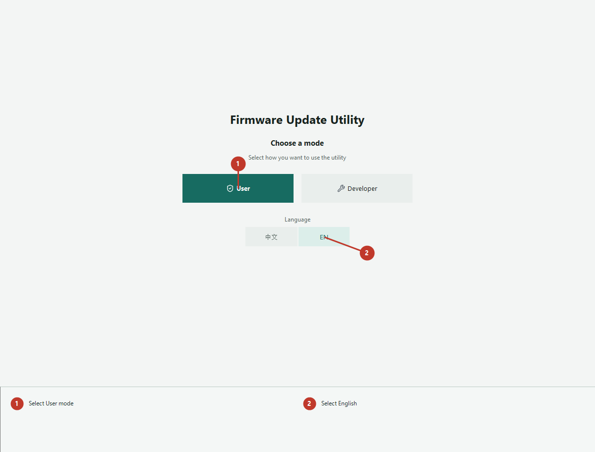
Step 3. Select User for the guided customer workflow. Select EN before entering the workflow to use the English interface.
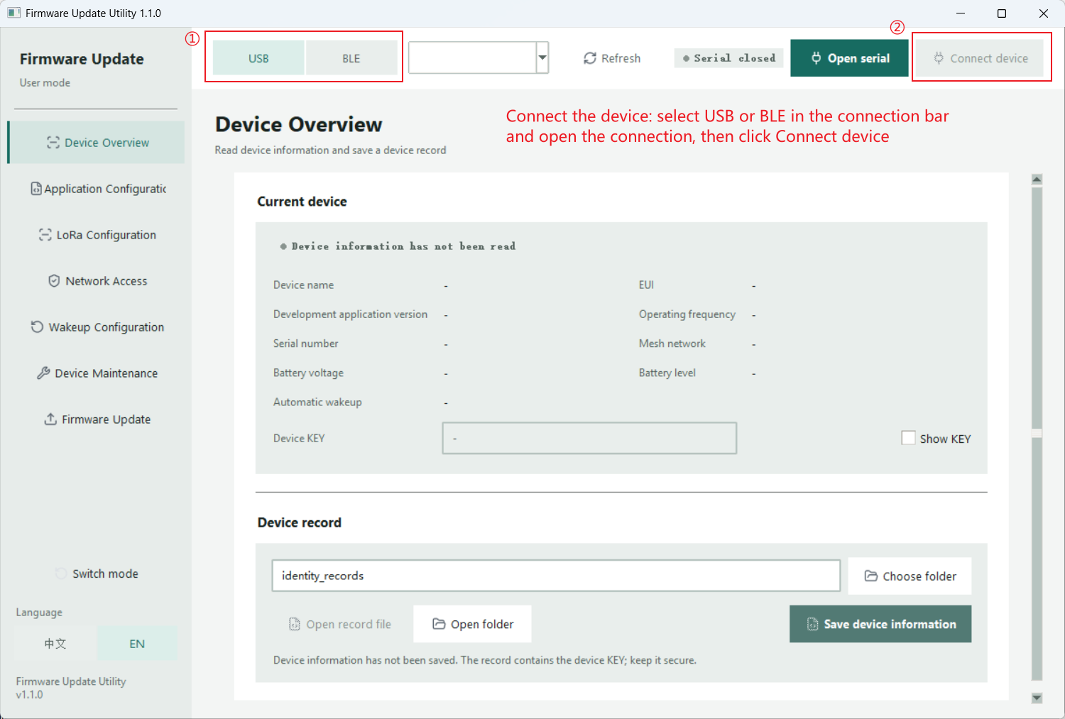
Step 4. Connect the device: select USB or BLE in the connection bar and open the connection, then click Connect device.
Step 5. Update the firmware: open Firmware Update, choose the supplied application firmware file, click Start update, and confirm the operation.
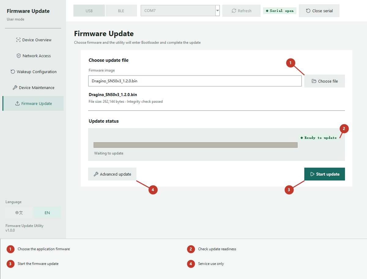
Step 6. Keep the device powered and connected during the update. The utility enters the Bootloader when needed, switches a wired link to high speed, writes the image, verifies it, and restarts the device.
Note: :
The final restart clears Mesh network enrollment. After the device starts, read its information and join it to the intended network again.
The application accepts .bin, .hex, and .ihex images. Use only firmware provided for the connected product.
Do not disconnect power or the data link during erase, write, verification, or restart.
Caution: :
Advanced update is intended for service and recovery work. Use it only when Dragino support provides the required procedure.
Firmware and changelog can be downloaded from: To be filled
7. FAQ
7.1 Questions about LoRaWAN
Learn more on https://wiki.dragino.com/docs/Configuration/end-node/lorawan-debug/
7.2 FPort5 does not upload
FPort 5 is usually triggered by downlink 0x26 01 or link detection. If the platform downlink does not actually reach the device, FPort 5 will not be sent. Check whether the LoRaWAN gateway or MA01-LN is online.
7.3 Mesh Node does not communicate when sleeping
Caution: :
The mesh node cannot join a mesh network, uplink sensor data or receive configuration commands while sleeping.
7.4 Device only prints bootloader log
This usually means the power supply is not enough. Please burn the correct MA01-LN bin file again.
7.5 Some nodes did not apply the synchronized wake-up configuration
Sync Wakeup Config is sent immediately over the Mesh network and is not queued for a sleeping node. Configure the network while nodes are awake.
7.6 Mesh Node can get the synchronized wake-up configuration automatically when joining network
MA01-LN will send the synchronized wake-up configuration to Mesh Node while inviting it to join the network. Thus, users only need to execute AT+MNWAKE before adding the first Mesh Node. Besides, after reset, Mesh Node will forget the previous network and wait to be invited to join.
7.7 Multiple gateway mesh network
Learn more on this link:MA01-LN Multi-Gateway Mesh Network
8 Order Info
9 Packing Info
10 Support
Support is provided Monday to Friday, from 09:00 to 18:00 GMT+8. Due to different timezones we cannot offer live support. However, your questions will be answered as soon as possible in the before-mentioned schedule.
Provide as much information as possible regarding your enquiry (product models, accurately describe your problem and steps to replicate it etc) and send a mail to Support@dragino.cc