DishSense
1. Introduction
1.1 What is DishSense Dishwasher Wireless Thermometer
DishSense is a professional-grade dishwasher thermometer designed for accurate and reliable temperature monitoring in commercial food service environments. Ideal for restaurants, central kitchens, food service establishments, and food processing facilities, DishSense ensures that critical temperatures required by hygiene standards are met during the high-temperature cleaning and sanitizing processes of dishwashers. Its precise monitoring helps verify sanitizing effectiveness, ensures tableware hygiene and safety, and meets HACCP compliance standards.
With built-in LoRaWAN connectivity, DishSense enables long-range, low-power, and maintenance-friendly data transmission even in complex commercial kitchen environments. Temperature records and sanitization status can be sent in real time to an IoT backend or kitchen management system, allowing operators to monitor dishwasher performance remotely, receive alerts when temperature thresholds are not met, and maintain traceable compliance logs without manual checks.
DishSense is ideal for environments requiring strict adherence to food safety regulations, such as restaurants, central kitchens, food service establishments, and food processing plants.
1.2 Features
- Dishwasher Thermometer– Designed specifically for dishwasher water temperature monitoring
- Food-Grade – Safe for food contact and dishwasher-compatible for easy cleaning
- LoRaWAN Connectivity – Enables long-range, low-power data transmission to IoT platforms
1.3 Specification
Supply Voltage:
- Built-in 2400mAh 3.0v CR17450 battery
Operating Temperature:
- -20°C ~ 93°C or -4°F ~ 199.4°F
- Accuracy: ±0.5°C or ±0.9°F
IP Rate: IP67
1.4 Applications
- Commercial Kitchen
- Restaurant
- Catering
- Food Processing
- Central Kitchen
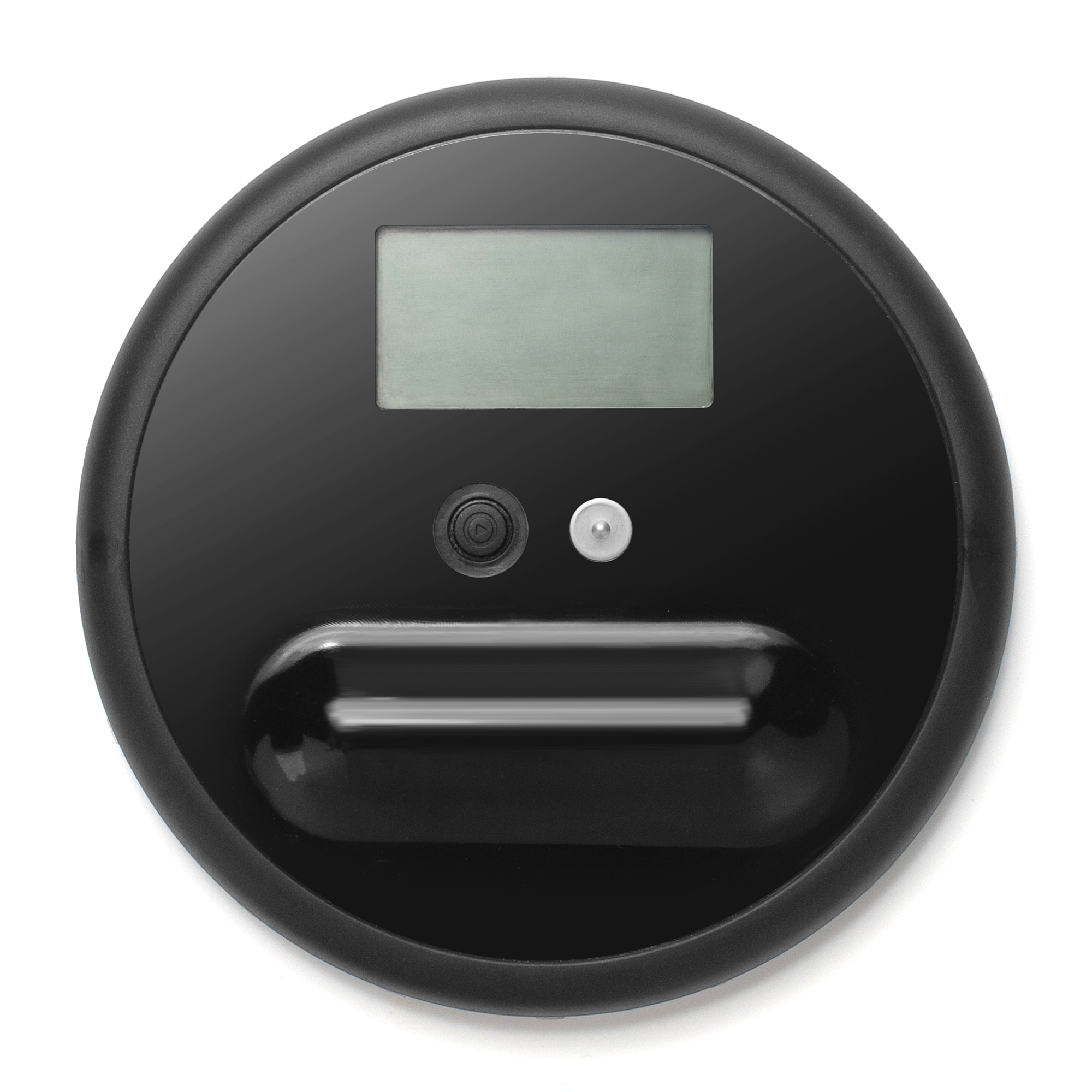
1.5 Product Apperance
1.6 LCD Display
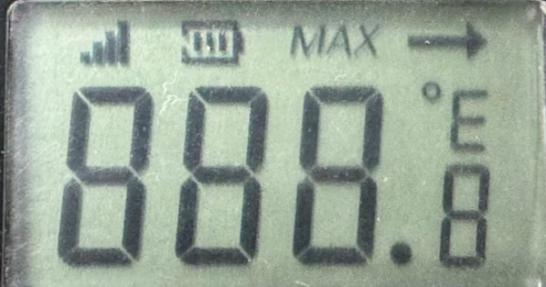
1.The above labels respectively indicate: signal, power, maximum temperature
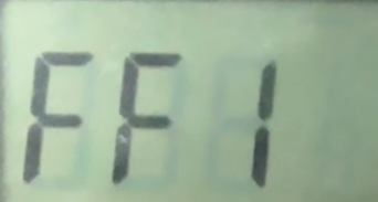
FF1 Meaningless
Power On:
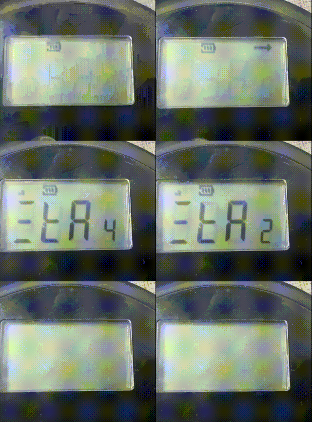
Each time powered on or reset, all segments of the LCD will be displayed in sequence and then disappear, then it will shows the current mod.
Example Display as below:
Registering LoRaWAN Network
After Power ON, the battery level will be displayed, and device will start to Join Network. Signal strength will be shown after network join successful, otherwise, there will no signal icon . The arrow will flash each time there is transmit to LoRaWAN or get a signal from LoRaWAN network.
Standby
After Join Successful, the device will show 5 to 0 and then enter Standby model.
In Standby mode, DishSense will:
- Turn off LCD to make sure the lowest power consumption.
- Send Keep Alive Message every 12 hours.
- Wait for user to push button to wait up and measure.
Notice: if Dishsense join fail to LoraWAN network, it will keep join to the network, untill successful. The join behaviour is as explain here:
- EU868 OTAA Join DR Logic. SF7->SF8->SF9->SF10->SF11->SF12; Each SF will make 3 attempts and then loop
- US915 and AU915 OTAA Join procedure,. End node by default will use all 72 channels (All sub-bands) to join and it will be set to use the proper sub-band after Join success
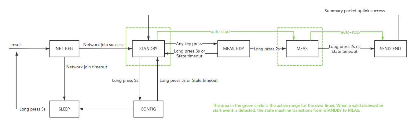
Measuring
-
Single press Button turn on display will show FFx (1s) and then last max temp 1s (Last: 38.4) and then display RDY (3 seconds)
-
Press and hold Button for 2 seconds to start new measure cycle. ( Display: GO 3 --> 2 --> 1 --> 0) and then start. Shows temperautre change in the first 5 seconds and then display turn off.
-
Place DishSense with other dishware before start of wash cycle.
-
During Measurement, Dishsense will send an uplink at the begining and send uplink every 15 seconds.For details on configuring the transmission of uplink data, please refer to commands such as AT+MEASBATCHSIZE.
-
After wash cycle, Press and hold Button for 2 seconds to check the Max TEMP and exit measure mode. Before exit the measurement mode, DishSense will send an uplink with MAX temp during the measure cycle. To make sure the uplink not lost, the uplink will use Datalog and Retry feature.
Minimum time is 90 seconds, download command is 39 00 00 00 09 Minimum time increment is 15 seconds, 105 seconds, download command is 39 00 00 00 0A Maximum time is 1200 seconds, download command is 39 00 00 00 50
Configure MODE
In Standand by mode:
Press and hold Button for 5 seconds to enter configure mode. User will see CFG (last 3 seconds), Press the button once will switch between below option. when display showing the option, press and hold Button for 3 seconds will enable the configure of this option:
- SLP: Deep Sleep Mode: Sensor doesn't have any LoRaWAN activate. This mode is used for storage and shipping to save battery life.
- RST: Reset DishSense to re-join network
- U C: Set unit to °C
- U F: Set unit to F°
- FF1: Set measuring mode to mod 1
Once the settings are complete, press and hold for 5 seconds to return to the standby screen (blank screen).
1.7 DishSense Detection Flowchart
DishSense Vibration-Activated Detection Flowchart
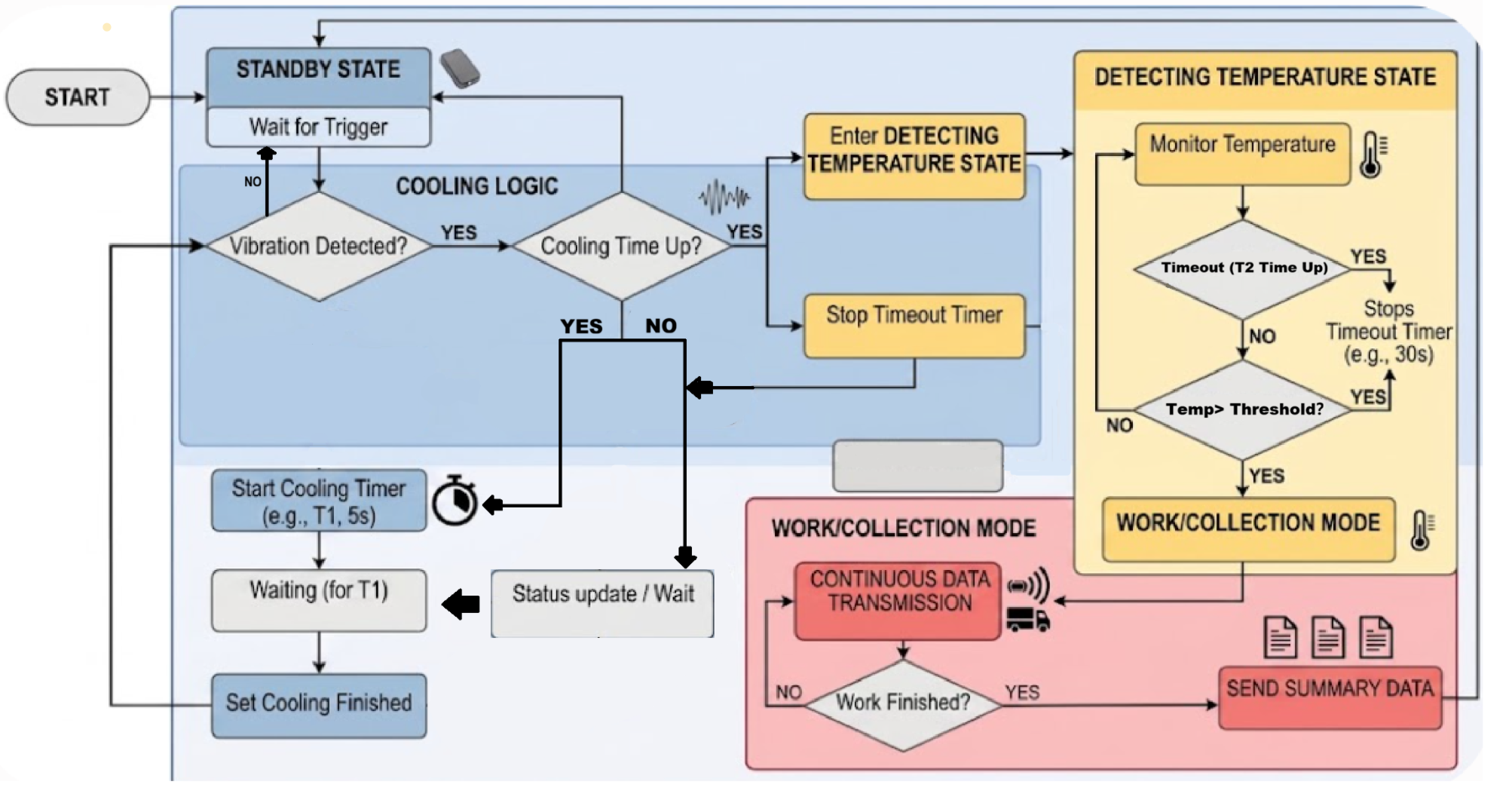
For information regarding vibration commands, please refer to the commands starting from section 3.3.16.
To configure the vibration sensor trigger threshold, use AT+VIBSET.
To configure the vibration-triggered startup function, use AT+DWDASSENB.
To configure the cool-down time after vibration-triggered startup, use AT+DWDASTCD.
To configure the temperature monitoring sampling frequency, use AT+DWD2PER.
To configure the temperature monitoring trigger threshold, use AT+DWD2TEMPTHR.
To configure the temperature monitoring timeout detection threshold, use AT+DWD2RISETMO.
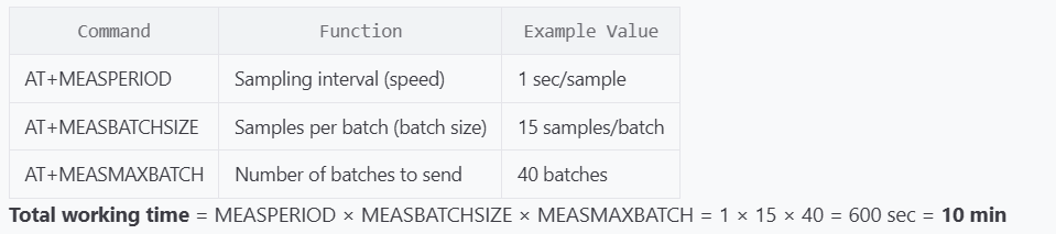
To configure the data acquisition duration, set the following:
AT+MEASSPERIOD Sampling interval (rate); default is 1 second.
AT+MEASBATCHSIZE Samples per group (batch size); default is 15 samples/group.
AT+MEASMAXBATCH Number of groups to send (total batches); default is 40 groups.
1.8 Some other instructions
The LCD transmission result shows 0, indicating that the transmission was successful, which means that the data packet was sent. In fact, the platform side may not receive it due to packet loss, but the actual fcnt has been increased, so the number of packets lost during the period can be determined by receiving the next unlost data packet. To ensure successful network access and reduce packet loss, good signal strength needs to be ensured. The device may not work when the battery power is too low. Pay attention to the upstream battery voltage.
2. Use DishSense
2.1 Quick guide to connect to a LoRaWAN server (OTAA)
In this example, we use The Things Stack as the LoRaWAN network server to show you how to register the DishSense with a LoRaWAN network server and how to activate it using OTAA. In this network diagram, the probe sends data packets to the charger/repeater unit via BLE. The repeater then converts those BLE data packets to LoRa packets and sends them to the Network Server.
In this example, we use the LPS8v2 as the LoRaWAN gateway.
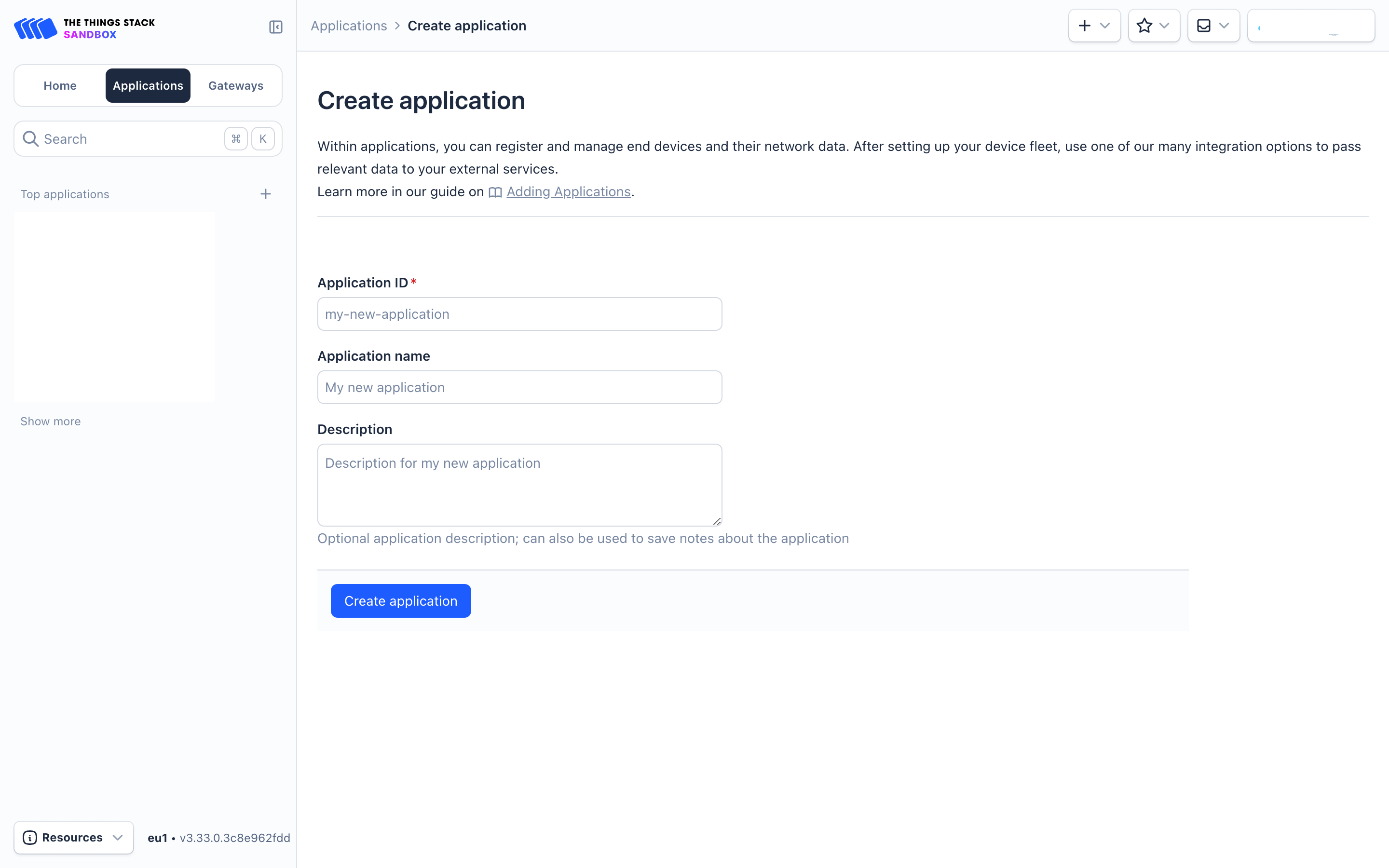
Sign up for a free account with The Things Stack Sandbox if you do not have one yet. Then, create an application as shown in the screenshots below.
Application ID: Provide a unique name to identify your application within The Things Stack, e.g., dragino-docs.
2.1.1 Adding manually
You can refer to the screenshots below to register your DishSense using The Things Stack's manual option.
On The Things Stack console:
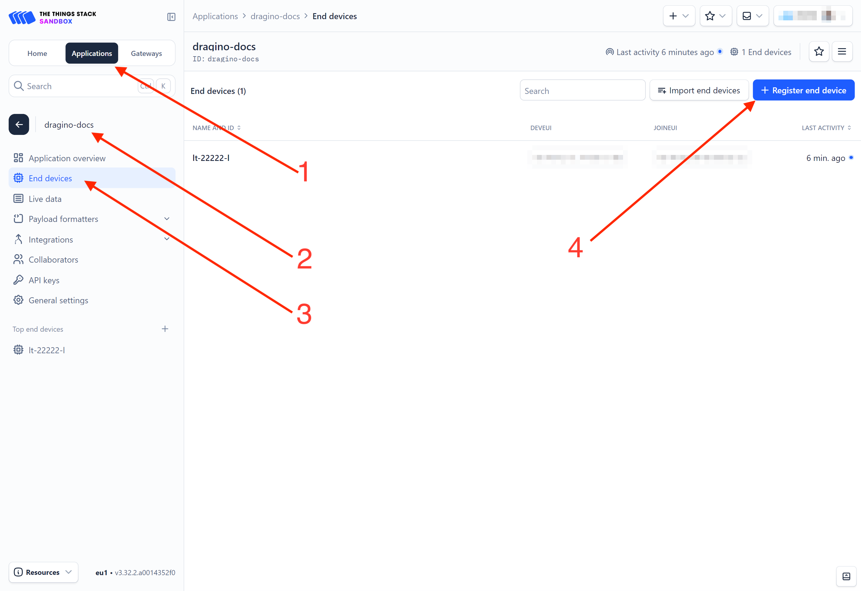
-
Click Applications.
-
Click <your application>. E.g. dragino-docs
3 Click End devices.
- Click + Register end device button.
-
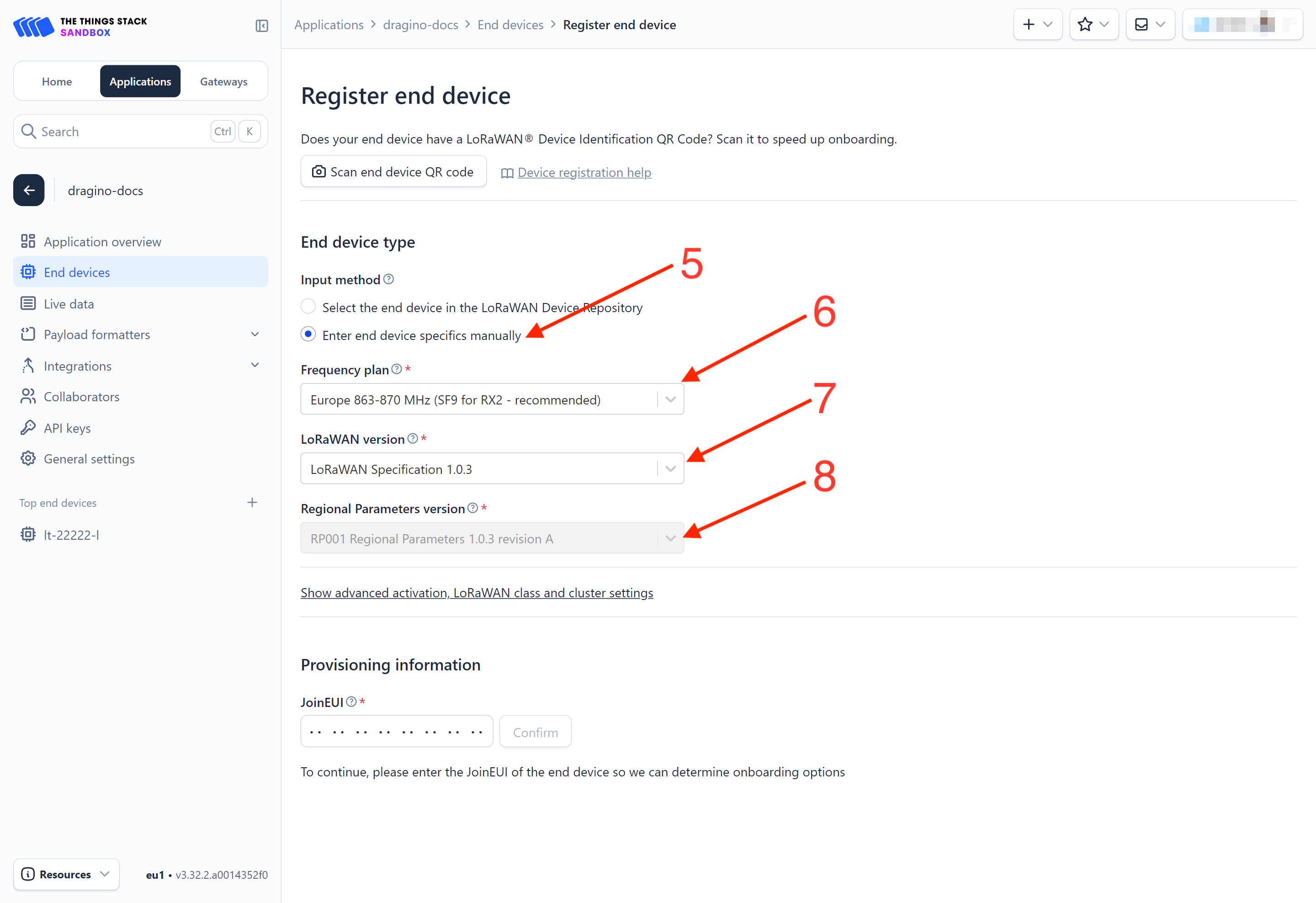
Select Enter end device specifies manually option.
-
Frequency plan: Select the frequency plan that matches your device. E.g.: Europe 863-870 MHz (SF9 for RX2 - recommended).
-
LoRaWAN version: LoRaWAN Specification 1.0.3
-
Regional Parameters version: You can't change it and it will select automatically.
-
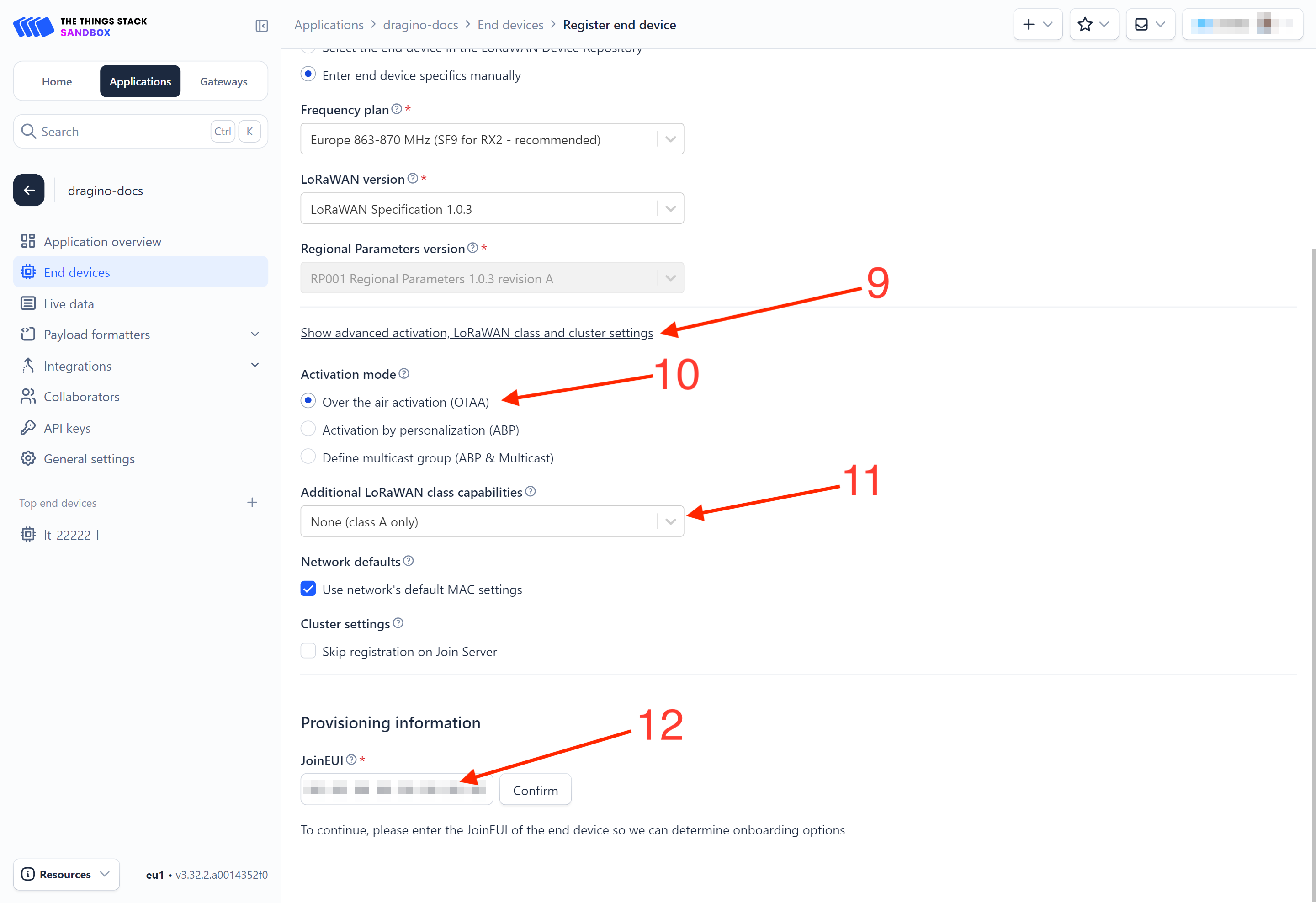
Click on the Show advanced activation, LoRaWAN class and cluster settings to expand the section.
-
Select Over the air activation (OTAA) option.
-
Select None (class A only).
-
JoinEUI: Enter the AppEUI of the device (see the registration information sticker) and Click the Confirm button.
-
DevEUI: Enter the DevEUI of the device (see the registration information sticker).
-
AppKey: Enter the AppKey of the device (see the registration information sticker).
-
End device ID: Enter a name for your end device to uniquely identify it within this application.
-
Click View registered end device option.
-
Click Register end device button.
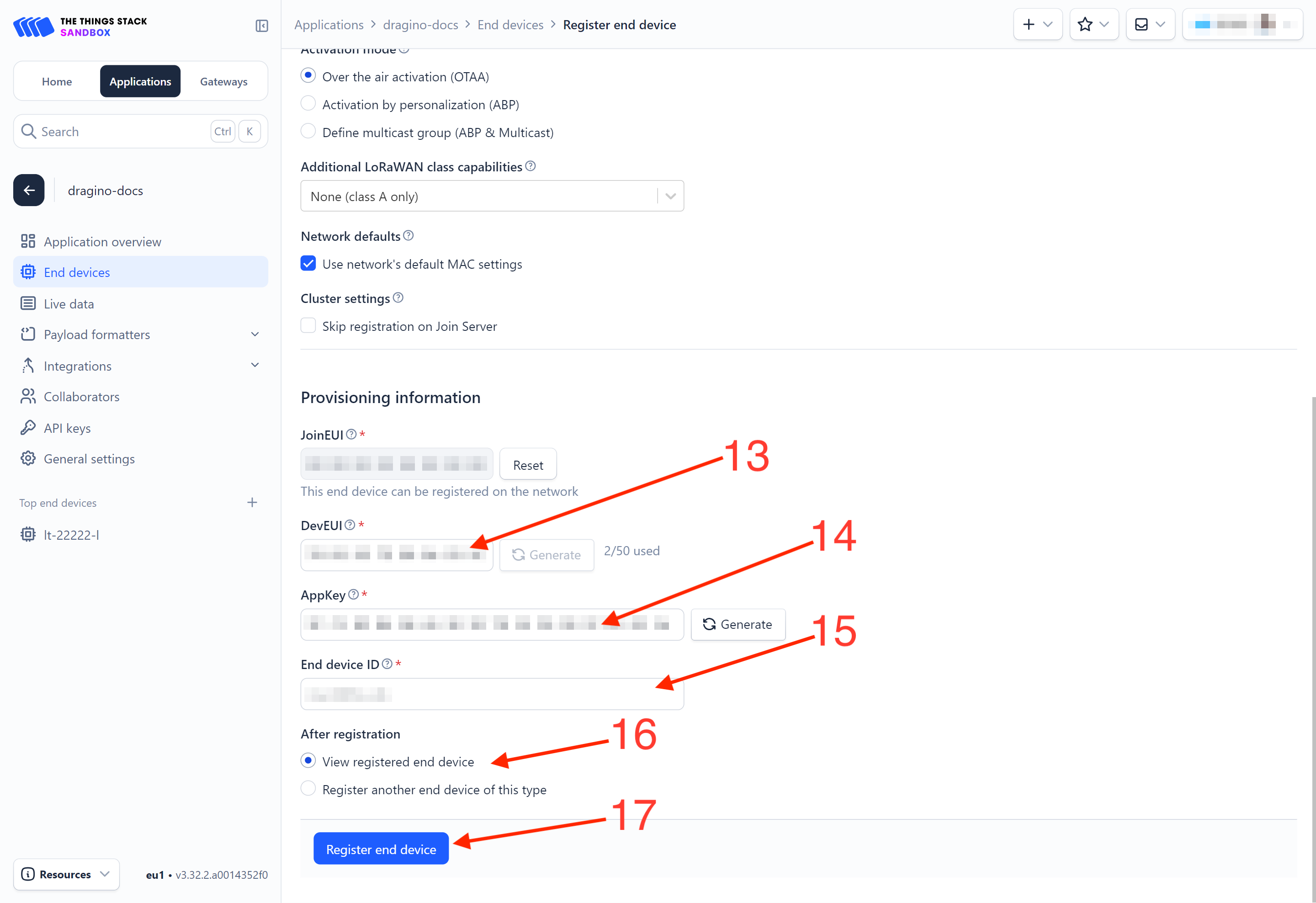
You will be navigated to the Device overview page.
2.1.2 Power on the DishSense
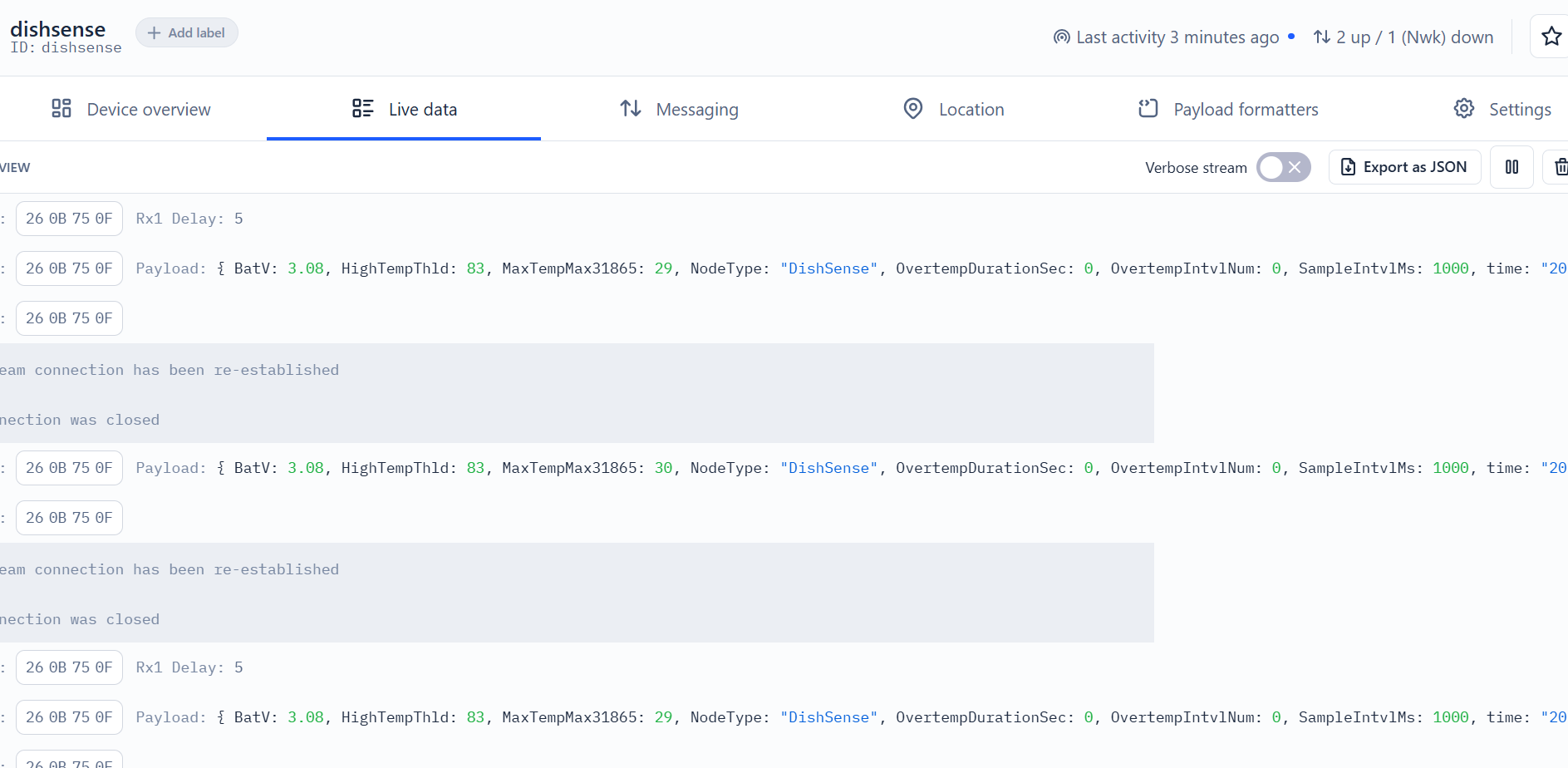
Power on the DishSense. It will then join The Things Stack. Once successfully connected, the device will begin uplinking sensor data to The Things Stack, which can be viewed on the Live data panel.
2.1.3 Uplink Decoder in The Things Stack
When the uplink payload arrives in The Things Stack, it is displayed in HEX format, which is not easy to read. You can add the DishSense decoder in The Things Stack for easier readability of each sensor reading.
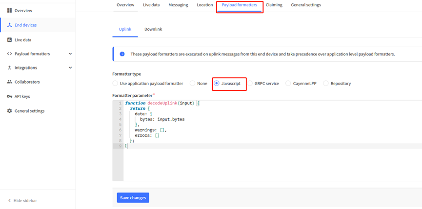
The uplink decoder can be added to thePayload Formatters of your device in The Things Stack. Refer to the screenshot below.
-
Click Uplink tab.
-
Formatter type: Select Custom Javascript formatter.
-
Formatter code: Copy the uplink payload formatter code from our dragino-end-node-decoder GitHub repository and paste it here.
-
Finally, click on the Save changes button.
2.2 LoRaWAN Uplink Payload
Uplink payloads include two types: Valid Sensor Values and other status/control commands.
- Valid Sensor Values: Use FPort=2.
- Other status/control commands: Use FPort other than 2
2.2.1 DishSense Working Modes FPort=2
This port is used for reporting probe placement status, charging events, and periodic keep-alive messages.
The payload includes the Timestamp, ProbeEvent, and the battery level of the charger/repeater box. The format is as follows:
timestamp (4 Bytes) + battery voltage (1 Byte, 0.02V) + MAX31865 maximum temperature (1 Byte, 1℃) + temperature threshold (1 Byte, 1℃) + Number of sampling intervals exceeding the temperature threshold (2 Bytes, up to 600 groups) + acquisition interval (2 Bytes, 1ms)
| Size(bytes) | 4 | 1 | 1 | 1 | 2 | 2 |
|---|---|---|---|---|---|---|
| Value | times tamp | BAT | max temp | temp threshold | Number of collections | collection interval |
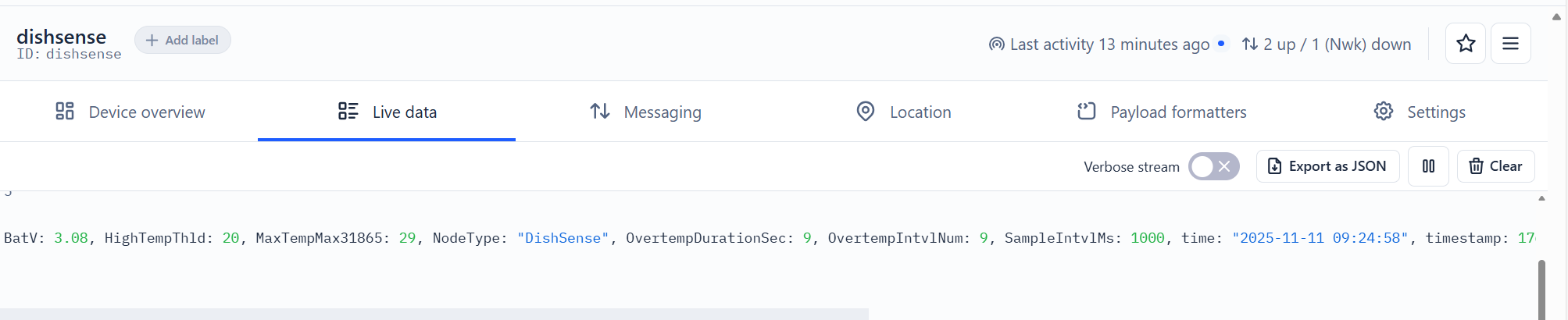
Example in The Things Stack: 691300EA 9A 1D 14 0009 03E8
Timestamp:0x691300EA=2025-11-11 09 : 24 : 58
BAT: ( 0x9A * 20) / 1000= 3.08V
max temp :0x1D=29
temp threshold:0x14=20
Number of collections:0x0009=9
collection interval:0x03E8=1000
2.2.2 Temperature acquisition, FPort=17/18
Disable the temperature calibration function; the uplink port is 17.
Enable the temperature calibration function; the uplink port is 18.
The specific corresponding command is AT+TEMPCALENB.
| Device Status (FPort=17/18) | |||||
| Size (bytes) | 4 | 1 | 1 | ||
| Value | times tamp | BAT | signedValue | ||

Example in The Things Stack:6A 7D 2F A5 9B 1C
Timestamp:0x6A 7D 2F A5=1786589093=2026-08-13 02:44:53
BAT: ( 0x9B * 20) / 1000= 3.1V
max temp :0x1C=28
2.2.3 Keep the device active, FPort=13
The specific corresponding command is AT+TDC.
| Device Status (FPort=13) | |||||
| Size (bytes) | 4 | 2 | |||
| Value | times tamp | BAT | |||

Example in The Things Stack:00 00 07 2B 0C 1C
Timestamp:0x00 00 07 2B=1835=1970-01-01 00:30:35
BAT: 0x0C1C / 1000= 3.1V
2.2.4 Device Status, FPort=5
You can use the downlink command (0x26 01) to request DishSense to send its configuration details, including the device configuration status. DishSense will uplink a payload to the LoRaWAN Network Server via FPort = 5.
The Payload format is as below.
| Device Status (FPort=5) | |||||
| Size (bytes) | 1 | 2 | 1 | 1 | 2 |
| Value | Sensor Model | Firmware Version | Frequency Band | Sub-band | BAT |
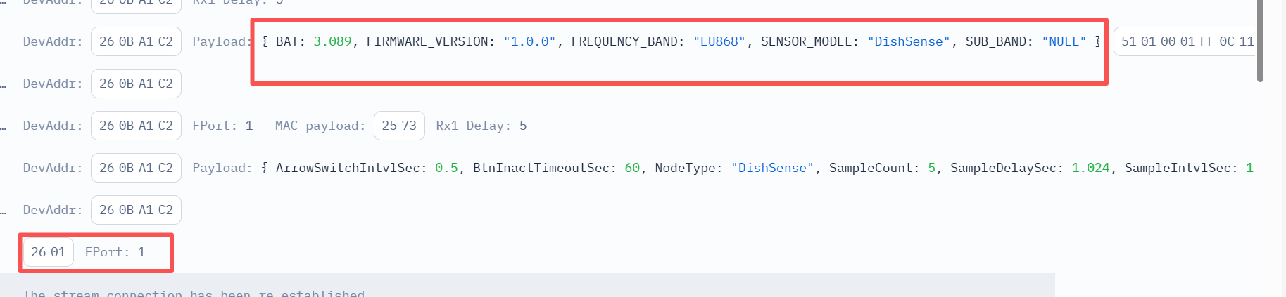
Example in The Things Stack: 51 0100 01 FF 0C11
Sensor Model: For DishSense, this value is 0x51
Firmware Version: 0x0100, which means v1.0.0
Frequency Band:
0x01: EU868
0x02: US915
0x03: IN865
0x04: AU915
0x05: KZ865
0x06: RU864
0x07: AS923
0x08: AS923-1
0x09: AS923-2
0x0a: AS923-3
0x0b: CN470
0x0c: EU433
0x0d: KR920
0x0e: MA869
Sub-Band:
AU915 and US915: value 0x00 ~ 0x08
CN470: value 0x0B ~ 0x0C
Other Bands: Always 0x00
BAT:0x0C11/1000=3.089v
2.3 Decode payload
While using TTN V3 network, you can add the payload format to decode the payload.
The payload decoder function for TTN V3 are here:
DishSense Payload Decoder: dragino-end-node-decoder/DishSense at main · dragino/dragino-end-node-decoder
3. Configure DishSense
3.1 Configure Methods
DishSense supports below configure method:
- AT Command via UART Connection : See UART Connection.
- LoRaWAN Downlink. Instruction for different platforms: See IoT LoRaWAN Server section.
3.2 General Commands
These commands are to configure:
- General system settings like: uplink interval.
- LoRaWAN protocol & radio related command.
They are same for all Dragino Devices which support DLWS-005 LoRaWAN Stack. These commands can be found here:
End Device AT Commands and Downlink Command
3.3 Commands special design for DishSense
These commands only valid for DishSense, as below:
3.3.1. Temperature Unit Change
Feature, Set the temperature unit AT Command: AT+TEMPUNIT
| Command Example | Function | Response |
|---|---|---|
| AT+TEMPUNIT=? | Query the current state. Unit: None. Default value: 0. | 0 |
| AT+TEMPUNIT=1 | Value range: 0 is Celsius, 1 is Fahrenheit. | OK |
3.3.2. Temperature Threshold
Feature: Set the high temperature threshold, used to calculate the time exceeding this threshold. AT Command: AT+TEMPTHLD
| Command Example | Function | Response |
|---|---|---|
| AT+TEMPTHLD=? | Query temperature threshold. Unit: Celsius. Default value: 8300 (actual temperature requires dividing by 100, which is 83.00 Celsius). | 8300 |
| AT+TEMPTHLD=8300 | Value range: -32768 ~ 32767. | OK |
3.3.3. Temperature Calibration Function Switch
Feature: 0 is sending its own data, 1 is adding the calibration offset. AT Command: AT+TEMPCALENB
| Command Example | Function | Response |
|---|---|---|
| AT+TEMPCALENB=? | Query the current state. Unit: None. Default value: 0. | 0 |
| AT+TEMPCALENB=1 | Value range: 0 is Close, 1 is Open. 0 is sending its own data, 1 is adding the calibration offset. | OK |
3.3.4. Clear Temperature Calibration Offset
Feature: Change AT+TEMPCALGEN to 0 value. AT Command: AT+TEMPCALRST
| Command Example | Function | Response |
|---|---|---|
| AT+TEMPCALRST | Clear the calibration offset. Unit: None. Default value: None. Value range: None. | OK |
3.3.5. Generate Temperature Calibration Offset
Feature, Generate an offset value based on ambient temperature AT Command: AT+TEMPCALGEN
| Command Example | Function | Response |
|---|---|---|
| AT+TEMPCALGEN=? | Query generated offset. Unit: Celsius. Default value: 0. When you want to query the difference between the sensor temperature and the real ambient temperature, input AT+TEMPCALGEN=?, the result obtained is -300, because 27-30=-3=-300. | 0 |
| AT+TEMPCALGEN=2700 | Parameter 'a' is the ambient temperature multiplied by 100. Value range: -2000 ~ 2000, i.e., -20.00℃ to 20.00℃. If the detected temperature is 30° and the real ambient temperature is 27°, then 'a' should be filled with 2700. After setting the command, the detected temperature in the same environment will be 27°. If the difference exceeds 20°, please use the AT+TEMPCALSET command to calibrate the data. | OK |
3.3.6. Force Set Temperature Calibration Offset
Feature, Forcibly set the temperature calibration offset value AT Command: AT+TEMPCALSET
| Command Example | Function | Response |
|---|---|---|
| AT+TEMPCALSET=? | Query set offset value. | 0 |
| AT+TEMPCALSET=1000 | Parameter 'a' is the ambient temperature multiplied by 100. Unit: None. Default value: None. Value range: -32768 ~ 32767. | OK |
3.3.7. Configure Temperature Sampling Period in Working Status
Feature, Set the period for temperature sampling during working status AT Command: AT+MEASSPERIOD
| Command Example | Function | Response |
|---|---|---|
| AT+MEASSPERIOD=? | Query sampling period. Unit: seconds. Default value: 1. | 1 |
| AT+MEASSPERIOD=1 | Value range: 1 - 14400. Example: It is only responsible for internally reading the PT100 sensor temperature data and will not upload data. Modification is not recommended, modifying the parameters will not help save power. | OK |
3.3.8. Configure PT100 Read Batch Size in Working Status
Feature, Set the read batch size during working status AT Command: AT+MEASBATCHSIZE
| Command Example | Function | Response |
|---|---|---|
| AT+MEASBATCHSIZE=? | Query read size. Unit: None. Default value: 15. | 15 |
| AT+MEASBATCHSIZE=15 | Value range: 15 - 65535. Example: AT+MEASBATCHSIZE=15, when 15 data points are read, the largest value among the 15 data points will be sent. | OK |
3.3.9. Configure Uplink Data Quantity in Working Status
Feature, Set the quantity of uplink data in working status AT Command: AT+MEASMAXBATCH
| Command Example | Function | Response |
|---|---|---|
| AT+MEASMAXBATCH=? | Query uplink quantity. Unit: None. Default value: 40. | 40 |
| AT+MEASMAXBATCH=40 | Value range: 1 - 65535. Example: AT+MEASMAXBATCH=40, it will exit working mode after sending data 40 times. | OK |
3.3.10. Set Maximum Runtime in Working Status
Feature, Configure the maximum runtime parameters during working status AT Command: AT+MEASMAXRUNTIME
| Command Example | Function | Response |
|---|---|---|
| AT+MEASMAXRUNTIME=? | This command can input parameter a, parameters ab, and parameters abc. If the 3rd parameter is omitted, or both 2nd and 3rd are omitted, default values are used. Using this command will automatically calculate the uplink data quantity for AT+MEASMAXBATCH. | 15,15,1 |
| AT+MEASMAXRUNTIME=60,30,2 | a Unit: seconds (Range: 15 ~ 4294967295). b Unit: None (Default: 15, Range: 15 ~ 65535, equivalent to AT+MEASBATCHSIZE setting). c Unit: seconds (Default: 1, Range: 1 ~ 14400, equivalent to AT+MEASSPERIOD setting). Example 1 (only A): AT+MEASMAXRUNTIME=60. Total working time is 60s, b defaults to 15 groups, c defaults to 1s collection, automatically calculates AT+MEASMAXBATCH=4 (4 uplink data). Example 2 (A and B): AT+MEASMAXRUNTIME=60,30. c defaults to 1s collection, automatically calculates AT+MEASMAXBATCH=2 (2 uplink data). Example 3 (ABC): AT+MEASMAXRUNTIME=60,30,2. Automatically calculates AT+MEASMAXBATCH=1 (1 uplink data). | OK |
3.3.11. Set Keep-alive Packet Interval
Feature: Keep the device active and send device status. AT Command: AT+TDC
| Command Example | Function | Response |
|---|---|---|
| AT+TDC=? | Query the interval time. Unit: seconds. Default value: 21600. | 21600 |
| AT+TDC=21600 | Value range: 6 ~ 86400. | OK |
3.3.12. Configure Network Join Timeout in Join Status
Feature: If network join is unsuccessful, it will continue to join, and if it exceeds the join time, it will enter sleep. AT Command: AT+NETREGTMO
| Command Example | Function | Response |
|---|---|---|
| AT+NETREGTMO=? | Query join timeout. Unit: minutes. Default value: 10. | 10 |
| AT+NETREGTMO=10 | Value range: 1 - 60. | OK |
3.3.13. Configure No Key Action Timeout in Working Ready Status
Feature: After entering ready, if it times out with no key action, it will return to the standby state. AT Command: AT+MEASRDYTMO
| Command Example | Function | Response |
|---|---|---|
| AT+MEASRDYTMO=? | Query timeout. Unit: seconds. Default value: 20. | 20 |
| AT+MEASRDYTMO=20 | Value range: 10 - 14400. | OK |
3.3.14. Configure No Key Action Timeout in Configure Status
Feature: After entering configure, if it times out with no key action, it will return to the standby state. AT Command: AT+CONFIGTMO
| Command Example | Function | Response |
|---|---|---|
| AT+CONFIGTMO=? | Query timeout. Unit: seconds. Default value: 120. | 120 |
| AT+CONFIGTMO=120 | Value range: 20 - 14400. | OK |
3.3.15. Acceleration Sensor Vibration Threshold Setting
Feature: Set the sensitivity for vibration triggering the working status. AT Command: AT+VIBSET
| Command Example | Function | Response |
|---|---|---|
| AT+VIBSET=? | Query current settings. | 0,0,6,5 |
| AT+VIBSET=0,0,6,5 | a Range (g, Default: 0, Range: 0-3 where 0: ±2g, 1: ±4g, 2: ±8g, 3: ±16g). b Frequency (Hz, Default: 0, Range: 0-4 where 0: 25Hz, 1: 50Hz, 2: 100Hz, 3: 200Hz, 4: 400Hz). c Threshold (Default: 6, Range: 2-127). d Duration (Default: 5, Range: 1-127). | OK |
3.3.16. Vibration Detection Function Switch
Feature, Set the vibration detection function on or off AT Command: AT+DWDASSENB
| Command Example | Function | Response |
|---|---|---|
| AT+DWDASSENB=? | Query the current state. Unit: None. Default value: 0. | 0 |
| AT+DWDASSENB=1 | Value range: 0 is Close, 1 is Open. | OK |
3.3.17. Automatic Function Detection Method
Feature, Set the detection method for the automatic function AT Command: AT+DWDASSSTRAT
| Command Example | Function | Response |
|---|---|---|
| AT+DWDASSSTRAT=? | Query detection method. Unit: None. Default value: 2. | 2 |
| AT+DWDASSSTRAT=2 | Value range: 1 uses detection method 1, 2 uses detection method 2. It has no effect, defaults to 2, and cannot be modified. | OK |
3.3.18. Vibration Function Cooling Time
Feature: When vibration detection is triggered, it enters cooling time. AT Command: AT+DWDASTCD
| Command Example | Function | Response |
|---|---|---|
| AT+DWDASTCD=? | Query cooling time. Unit: minutes. Default value: 240. | 240 |
| AT+DWDASTCD=240 | Value range: 0 - 14400 minutes. Regardless of whether it enters the working state, it will enter the vibration detection cooling time, and vibration detection can only be used again after the cooling time ends. | OK |
3.3.19. Temperature Sampling Interval for Automatic Function 2 Temperature Rise Detection
Feature: After vibration detection is triggered, the detected temperature sampling interval can be seen through the serial port. AT Command: AT+DWD2PER
| Command Example | Function | Response |
|---|---|---|
| AT+DWD2PER=? | Query sampling interval. Unit: seconds. Default value: 1. | 1 |
| AT+DWD2PER=1 | Value range: 1 - 300 seconds. | OK |
3.3.20. Temperature Thresholds for Automatic Function 2 Temperature Rise Detection
Feature, Set heating start and cooling end temperature thresholds AT Command: AT+DWD2TEMPTHR
| Command Example | Function | Response |
|---|---|---|
| AT+DWD2TEMPTHR=? | Query temperature thresholds. Unit: ℃. Default values: Heating start 40.0, Cooling end 35.0. | 40.0,35.0 |
| AT+DWD2TEMPTHR=40.0,35.0 | a is heating start threshold (range: 40.0 - 60.0). b is cooling end threshold (range: 20.0 - 39.0). | OK |
3.3.21. Temperature Rise Detection Timeout for Automatic Function 2
Feature: When vibration detection is triggered, if the temperature threshold is not reached for more than the specified time, it will exit temperature rise detection and return to the standby state. AT Command: AT+DWD2RISETMO
| Command Example | Function | Response |
|---|---|---|
| AT+DWD2RISETMO=? | Query timeout time. Unit: seconds. Default value: 600. | 600 |
| AT+DWD2RISETMO=600 | Value range: 10 - 14400 seconds. | OK |
4. Firmware update
User can change firmware DishSense to:
- Change Frequency band/ region.
- Update with new features.
- Fix bugs.
Firmware and changelog can be downloaded from : Firmware download link
Methods to Update Firmware:
- (Recommanded way) OTA firmware update via wireless: Firmware OTA Update for LoRaWAN End Node
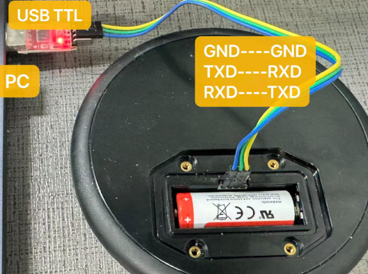
- Update through UART TTL interface: Instruction.
5. FAQ
5.1 How many packets will be sent in each wash circle?
To configure the data acquisition duration, set the following:
AT+MEASSPERIOD Sampling interval (rate); default is 1 second.
AT+MEASBATCHSIZE Samples per group (batch size); default is 15 samples/group.
AT+MEASMAXBATCH Number of groups to send (total batches); default is 40 groups.
The AT+MEASMAXRUNTIME command accepts three parameters.
Using this command automatically calculates the uplink data volume for AT+MEASMAXBATCH; please refer to section 3.3.10 for details.
6. Order Info
Part Number: DishSense-XX
XX:
- EU433: Frequency bands EU433
- EU868: Frequency bands EU868
- KR920: Frequency bands KR920
- CN470: Frequency bands CN470
- AS923: Frequency bands AS923
- AU915: Frequency bands AU915
- US915: Frequency bands US915
- IN865: Frequency bands IN865
- CN779: Frequency bands CN779
7. Packing Info
Package Includes:
- DishSense x 1
Dimension and weight:
- Package Size / pcs : 1908050mm
- Weight / pcs : 310g
8. Support
- Support is available Monday to Friday, from 09:00 to 18:00 GMT+8. Due to different time zones, we cannot offer live support. However, your questions will be answered as soon as possible within the above-mentioned schedule.
- Please provide as much information as possible regarding your inquiry (product models, a detailed description of the problem, and steps to reproduce it) and send an email to support@dragino.com.